Sign In
Upload
Manuals
Brands
Wacker Neuson Manuals
Inverter
G 240
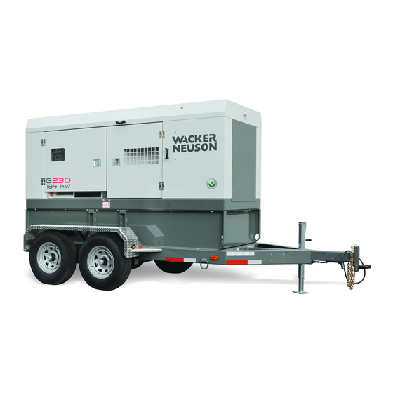
User Manuals: Wacker Neuson G 240 Mobile Generator
Manuals and User Guides for Wacker Neuson G 240 Mobile Generator. We have
3
Wacker Neuson G 240 Mobile Generator manuals available for free PDF download: Operator's Manual, Parts Book
Wacker Neuson G 240 Operator's Manual (254 pages)
Mobile Generator
Brand:
Wacker Neuson
| Category:
Inverter
| Size: 25 MB
Table of Contents
G 230 / G 240
7
Foreword
4
Table of Contents
7
1 Safety Information
13
Signal Words Used in this Manual
13
Machine Description and Intended Use
14
Safety Guidelines for Operating the Machine
15
Service Safety
17
Operator Safety While Using Internal Combustion Engines
19
Safety Guidelines for Mobile Generators
20
Safety Guidelines for Towing the Machine
22
Safety Guidelines for Lifting the Machine
23
Reporting Safety Defects
23
2 Label Locations
24
3 Label Meanings
26
4 Lifting and Transporting
36
Lifting the Machine
36
Before Towing Checklist
37
Towing the Machine
38
Preparing the Machine for Transport on a Truck or Trailer
39
Hazardous Materials Placards
40
Testing the Breakaway System (Hydraulic Surge Brakes)
41
Testing the Breakaway System (Electric Brakes)
43
5 Machine Setup
45
Preparing the Machine for First Use
45
Positioning the Machine
46
Grounding the Generator
48
Recommended Fuel
49
Refueling the Machine (Basler Controller)
50
Refueling the Machine (Deep Sea Controller)
51
6 Operation, Control, and Component Locations
52
Control / Component Locations
52
Main Circuit Breaker
54
Engine Start Switch
55
Genset Pre-Alarms and Alarms (Shut-Down Conditions)
56
Overcurrent Condition
57
Idle Switch
57
Diesel Particulate Filter (DPF)
58
Using the Lugs and the Convenience Receptacles
59
Selecting the Voltage
60
Before Starting the Machine
63
Starting and Running the Generator
64
Stopping the Machine
66
Emergency Stop Switch
66
LCD Panel: Monitoring Machine Operation
67
8 Working with Basler Controller
69
How to Use the Genset Controller LCD and Keypad
69
Menu Diagram of the Genset Controller
70
Menu Diagram Components
71
Using the Metering and Settings Menus
72
Logging in to the Genset Controller by Entering the Password
73
Adjusting the LCD Screen Contrast
76
Changing the Time/Date Settings
77
Changing the Sender Fail Time Delays
78
Changing the Units of Measure
80
Changing the Low Fuel Pre-Alarm Setting
82
Changing or Disabling the Low Fuel Alarm Setting
84
Changing the Cooldown Time Setting
86
Changing the Pre-Crank Time Delay (Glow Plug Timer)
88
Changing the Maintenance Interval
90
Resetting the Maintenance Interval Pre-Alarm
92
Resetting a Loss of Voltage Pre-Alarm
94
Accessing and Using the Event Log
95
9 Operation (Deep Sea Controller)
97
Main Circuit Breaker
97
Genset Controller Power Switch
98
Selecting the Voltage
99
Deep Sea Controller Buttons/Functions
102
Genset Controller Alarms and Shut-Down Conditions
104
Before Starting the Machine
106
Starting and Running the Generator
107
Stopping the Generator
109
Emergency Stop Switch
110
Engine and Generator Monitoring
111
10 Working with Deep Sea Controller: DSE 7310
112
Introduction
112
Navigating the Menus
113
Adjusting Screen Contrast
115
How to Reset the Maintenance Timer
116
11 How to Connect Loads
117
Lug Terminal Connection Diagrams
117
Best Practices for Balancing Loads
118
Connecting 480V, 3-Phase and Single-Phase Loads
120
Connecting a 240V 3Ø Load and a 240V 1Ø Load
121
Connecting a 220-240V 3Ø Load and Multiple 127-133V 1Ø Loads
122
Connecting a 208V 3Ø Load and Multiple 120V 1Ø Loads
123
12 Using Remote Start Capabilities
124
Remote Run Terminal Block
124
Remote Transfer Switch
125
Preparing for Automatic/Remote Start-Up (Basler)
126
Preparing for Automatic/Remote Start-Up (Deep Sea)
127
13 Diagnostic Trouble Codes (DTC)
129
Accessing Dtcs with the Basler Controller
129
Accessing Engine Dtcs Using the Deep Sea Controller
130
List of Engine Diagnostic Trouble Codes (Dtcs)
131
14 Factory-Installed Options
145
Battery Charger
145
Lockable Battery Disconnect
146
Camlocks
147
Containment System
148
Extended Run Tank (ERT)
148
Engine Block Heater
149
Automatic LCD Heat
149
Low Coolant Shutdown
150
Temperature-Activated Shutters
151
Positive Air Shutoff Valve
152
Quick-Disconnect Fuel Fittings
153
Lube Level Maintainer
154
15 Machines with Aftertreatment Exhaust System
155
How the Aftertreatment Exhaust System Works
155
Filling the DEF Tank
156
Shelf Life of Diesel Exhaust Fluid (DEF)
158
Monitoring and Control of the DEF Level
159
Monitoring DEF Quality
160
Conditioning the Aftertreatment Exhaust System (if Equipped)
161
16 General Maintenance
162
Periodic Maintenance Schedule
162
Maintaining the Emission Control System
163
Preparing for Maintenance
163
Cleaning the Machine
163
Inspecting the Machine
164
Maintaining the Trailer
165
Checking and Draining the Containment System
166
Checking the Exhaust System
167
Maintaining the Battery
168
Cleaning the Diesel Particulate Filter (DPF) (if Equipped)
169
Filling the Radiator
170
Replacing the Aftertreatment DEF Dosing Unit Filter
172
Storage
174
Machine Disposal / Decommissioning
175
17 Engine Maintenance: John Deere 4045TF285/HF285 6068HF285
176
18 Engine Maintenance: T4I Cummins QSB6.7
181
19 Engine Maintenance: T4F Cummins QSB7-G9
185
Maintenance Schedule
187
20 Troubleshooting
189
21 Technical Data - G
190
Engine
190
Generator
191
Trailer and Skid
191
Dimensions
192
22 Technical Data - G
192
Engine: G 230 T4F
193
Engine: G 230 T4I
194
Generator
195
Trailer and Skid
196
Dimensions
197
Tire Safety Information
198
23 User's Information for Transport Canada Fuel Tank
210
24 Emission Control Systems Information and Warranty-Diesel
213
Emission Control System Background Information
213
Limited Defect Warranty for Exhaust Emission Control System
214
Limited Defect Warranty for Wacker Neuson Emission Control Systems
214
25 General Machine Schematics
217
Fuses
217
Trailer Wiring
218
Trailer Wiring Components
219
AC Schematic: G 230/G 240
220
AC Schematic Components: G 230/G 240
221
DC Schematic: G 240 John Deere Tier 3
222
DC Schematic Components: G 240 Tier 3
223
DC Schematic: G230 Cummins T4I
224
DC Schematic Components: G 230 T4I
225
DC Schematic: G230 Cummins T4F
226
DC Schematic Components: G 230 Cummins T4F
227
DC Electrical Schematic Section A: G 230 Cummins T4F
228
Electrical Schematic Components
229
DC Electrical Schematic Section B: G 230 Cummins T4F
230
Electrical Schematic Components
231
DC Electrical Schematic Section C: G 230 Cummins T4F
232
Electrical Schematic Components
233
Cummins Engine Relays and Fuses
234
Cummins Engine Relays and Fuses
235
27 Schematics, Machines with Deep Sea Controller
236
AC Schematic: G 230 / G 240
236
Electrical Schematic Components: G 230 / G 240
237
DC Schematic: G 240 John Deere Tier 3
238
DC Schematic Components: G 240 John Deere Tier 3
239
DC Schematic: G 230 Cummins T4I
240
Table of Contents
240
DC Schematic: G 230 Cummins T4I
240
DC Schematic Components: G 230 Cummins T4I
241
DC Schematic: G 230 Cummins T4F
242
DC Schematic Components: G 230 Cummins T4F
243
DC Electrical Schematic Section A: G 230 Cummins T4F
244
Electrical Schematic Components
245
DC Electrical Schematic Section B: G 230 Cummins T4F
246
Electrical Schematic Components
247
DC Electrical Schematic Section C: G 230 Cummins T4F
248
Electrical Schematic Components
249
Cummins Engine Relays and Fuses
250
Cummins Engine Relays and Fuses
251
Advertisement
Wacker Neuson G 240 Parts Book (200 pages)
Brand:
Wacker Neuson
| Category:
Portable Generator
| Size: 10 MB
Table of Contents
Français
5
Table of Contents
5
Fuel Fill Corner
10
Kraftstoff-Füller Eckwand
10
Esquina Boca de Llenado Combustible
10
Support À Équerre - Remplisseur de Carburant
10
Front Panel Blechtafel Vorne Conjunto Panel Delantero Tableau de Front
12
Right Rear Panel
14
Blechtafel Hinten & Rechts
14
Panel Trasero y Derecho
14
Tableau D'arrière Et À Droite
14
Rear Air Inlet
16
Lufteinlass (Hinten)
16
Entrada de Aire (de Atrás)
16
Admission À Air (Arrière)
16
Rear Left Door
18
Linke Tür Hinten
18
Puerta Trasera Izquierda
18
Porte-D'arrière Gauche
18
Right Rear Door
20
Rechte Tür Hinten
20
Puerta Trasera Derecha
20
Porte D'arrière/Droite
20
Front Left Door
22
Linke Tür Vorne
22
Puerta Delantera Izquierda
22
Porte de Front/Gauche
22
Right Front Door
24
Rechte Tür Vorne
24
Puerta Delantera Derecha
24
Porte de Front/Droite
24
Main Breaker/Voltage Selector Panel
26
Hauptunterbrecher/Spannungswähler
26
Interruptor de Circuito Principal/Selector de Voltaje
26
Coupe-Circuit Principal/Selecteur de Voltage
26
Current Transformer Stromwandler Transformador de Corriente Transformateur du Courant
30
Lug Box
32
Anschlusskasten Caja de Conexiones Boîte de Cosses Terminales
32
Lugs/Breakers/Receptacles
34
Anschlüsse/Unterbrecher/Steckdosen
34
Conexiones/Interruptores/Tomacorrientes
34
Cosses Terminales/Disjoncteurs/Prises de Courant
34
Fuse Block/Relay
36
Sicherungsblock/Relais
36
Bloque de Fusibles/Relai
36
Bloc À Fusibles/Relais
36
Front Enclosure/Radiator
38
Gehäuse Vorne / Kühler
38
Caja Delantera / Radiador
38
Carter de Front / Radiateur
38
Radiator Hoses Kühlerschläuche Mangueras del Radiador Tuyaux du Radiateur
42
Rear Panels/Muffler
44
Blechtafeln Hinten / Auspufftopf
44
Paneles Traseros / Silenciador
44
Tableaux D'arrière / Pot D'échappement
44
Generator/Engine Motor/Generator Motor/Generador Moteur/Générateur
46
Generator/Engine Motor/Generator Motor/Generador Moteur/Générateur
47
Control Panel/Air Cleaner
52
Schalttafel/Luftfilter
52
Tablero de Mando/Filtro de Aire
52
Tableau de Commande/Filtre À Air
52
Air Cleaner Luftfilter Filtro del Aire Filtre À Air
54
Engine Control Module/Voltage Regulator
56
Motorkontrollmodul/Spannungsregler
56
Módulo de Mando del Motor / Regulador de Voltaje
56
Module de Contrôle de Moteur / Régulateur de Tension
56
Fan Guard Lüfterhaube Guardaventilador Bague de Ventilateur
58
Battery Batterie Batería Batterie
60
Oil Bypass Assembly
62
Öl-Bypass
62
Conjunto Bypass de Aceite Jeu de Dérivation de L'huile
62
Skid Assembly
64
Unterbau
64
Conjunto Patín
64
Base du Générateur Compl
64
Fuel Tank Kraftstofftank Depósito de Combustible Réservoir de Carburant
66
Fuel Hose Kraftstoffleitung Manguera de Combustible Tuyau de Carburant
68
Roof Panel Dachblechtafel Panel del Techo Tableau de Toit
70
Sheet Metal Assembly
72
Blechaufbau
72
Conjunto Planchas de Metal
72
Plaques de Métal
72
Engine-Deere Deere-Motor Motor Deere Moteur Deere
74
Safety Labels Sicherheitsaufkleber Calcomanías de Advertencias Autocollants de Sécurité
76
Labels - Control Panel & Controller
78
Aufkleber - Schalttafel und Kontroller
78
Calcomanias - Tablero de Mando y Controlador
78
Autocollants - Tableau de Commande Et Contrôleur
78
Labels Aufkleber Calcomanias Autocollants
80
Factory-Installed Options
83
Fabrikfertiges Sonderzubehör
83
Opciones Instaladas en la Fábrica
83
Options Installées À L'usine
83
LCD Strip Heater
84
Heizgerät des LCD-Displays
84
Calentador de la Pantalla LCD
84
Réchauffeur À Bande D'acl
84
Lube Level Maintainer-Extra Large
86
Schmierölstandhaltung (Zusätzlich Groß)
86
Mantenedor de Nivel de Lubricación (Muy Grande)
86
Régulateur de Lubrifiant Pour Groupes Supplémentaire Grandes
86
Option-Engine Block Heater
90
Sonderzubehör-Heizapparat
90
Opción de Calentador para Bloque del Motor
90
Option de Appareil de Chauffage
90
Low Coolant Shutdown
92
Niedrigkühlmittelabschaltungssystem
92
Apagador por Bajo Nivel de Refrigerante
92
Dispositif D'arrêt Pour Bas Niveau de Liquide de Refroidissement
92
Radiator Shutter Kühlerabdeckung Persiana del Radiador Obturateur du Radiateur
94
Battery Disconnect
98
Batterietrennung
98
Desconexión de la Batería
98
Sectionneur de la Batterie
98
Racor Heater Racor-Heizapparat Calentador Racor Appareil de Chauffage Racor
100
Trailer Frame W/Surge Brake
103
Anhängerrahmen mit Hydraulikbremse
103
Chasis de Remolque con Freno Hidráulico
103
Trailer Frame W/Surge Brake
104
Châssis de Remorque Avec Frein Hydraulique
104
Anhängerrahmen mit Hydraulikbremse
105
Chasis de Remolque con Freno Hidráulico
105
Châssis de Remorque Avec Frein Hydraulique
105
Hub Nabe Cubo Moyeu
108
Surge Brake Hydraulikbremse Freno Hidráulico Frien Hydraulique
110
Trailer Frame W/Electric Brake
113
Anhängerrahmen mit Elektrik-Bremse
113
Chasis de Remolque con Freno Eléctrico
113
Châssis de Remorque Avec Frein Électrique
113
Trailer Frame W/Electric Brake
114
Anhängerrahmen mit Elektrik-Bremse
114
Chasis de Remolque con Freno Eléctrico
114
Châssis de Remorque Avec Frein Électrique
114
Hub Nabe Cubo Moyeu
118
Electric Brake Elektrik-Bremse Freno Eléctrico Frein Électrique
120
Español
127
1 Información de Seguridad
129
Símbolos que Aparecen en Este Manual
129
Pautas de Seguridad para la Operación de la Máquina
130
Seguridad en el Remolque
132
Pautas para la Seguridad Durante el Servicio
132
Ubicación de las Calcomanías
134
Calcomanías de Seguridad y Advertencia
136
Calcomanías de Información
139
2 Operación
143
Aplicación
143
Panel de Control
144
Secuencia de Arranque Normal
146
Supervisión del Generador
148
Supervisión del Motor
149
Fallas de Parada del Motor
150
Falla por Sobrecorriente
151
Luz de Advertencia
152
Selector de Voltaje
153
Interruptor de Parada de Emergencia
155
Interruptor de Circuito de la Línea Principal
156
Interruptor de Arranque del Motor
157
Ajuste del Voltaje con el Reóstato
158
Lengüetas de Conexión
159
Conexión a Tierra
160
Tomacorrientes
161
Bloque de Terminales, Marcha Remota
162
Calcomanía del Selector de Voltaje
163
Antes del Arranque
164
Arranque Manual
166
Marcha del Generador
168
Factores de Corrección de Potencia del Motor
169
Apagado del Generador
170
Arranque en Clima Frío
170
Elevación
170
Almacenamiento de un Día para Otro
171
Almacenamiento a Largo Plazo
171
Arranque Automático/Remoto
172
Interruptor Remoto/De Transferencia
173
Remolque
174
3 Mantenimiento
176
Programa de Mantenimiento Periódico
176
Rodaje de Máquinas Nuevas
178
Restablecimiento del Temporizador de Mantenimiento Periódico
178
Reemplazo del Elemento de Filtro de Aire
179
Lubricación del Motor
180
Revisión del Nivel de Refrigerante del Motor
181
Mantenimiento del Remolque
182
4 Opciones Instaladas de Fábrica
183
Calefactor de Motor
183
Calentador de Banda de LCD
184
Parada por Bajo Nivel de Refrigerante
185
Conservador del Nivel de Lubricante
186
Persianas Activadas por Temperatura
187
Desconexión de la Batería Trabable
187
5 Esquema
188
Esquema de CC (G 150 / G 180 / G 240)
188
Componentes del Esquema de CC
189
Esquema de CA (G 150 / G 180)
190
Componentes Esquemáticos de CA (G 150 / G 180)
191
Esquema de CA (G 240)
192
Componentes Esquemáticos de CA (G 240)
193
6 Datos Técnicos
194
Motor
194
Datos del Generador
195
Datos del Remolque y Paletas
196
Dimensiones
197
Wacker Neuson G 240 Operator's Manual (74 pages)
Mobile Generator
Brand:
Wacker Neuson
| Category:
Portable Generator
| Size: 5 MB
Table of Contents
Foreword
3
Table of Contents
5
Safety Information
7
Signal Words Found in this Manual
7
Safety Guidelines for Operating the Machine
8
Operator Safety While Using Internal Combustion Engines
9
Towing Safety
10
Guidelines for Service Safety
10
Label Locations
12
Safety and Warning Labels
14
Informational Labels
17
Operation
21
Application
21
Control Panel
22
Normal Boot-Up Sequence
24
Generator Monitoring
26
Engine Monitoring
27
Engine Shutdown Faults
28
Current Overload Fault
29
Warning Light
30
Voltage Selector
31
Emergency Stop Switch
32
Main Line Circuit Breaker
33
Engine Start Switch
34
Adjusting Voltage with the Rheostat
35
Connection Lugs
36
Ground Connection
36
Convenience Receptacles
37
Remote Run Terminal Block
38
Voltage Selector Label
39
Before Starting
40
Manual Start-Up
41
Running the Generator
43
Engine Power Correction Factors
44
Racor® Filter
45
Shutting off the Generator
45
Cold Weather Start-Up
46
Lifting
46
Overnight Storage
46
Long-Term Storage
46
Automatic/Remote Start-Up
47
Remote/Transfer Switch
48
Towing
49
Maintenance
51
Periodic Maintenance Schedule
51
Breaking in New Machines
52
Resetting the Periodic Maintenance Timer
52
Replacing the Air Filter Element
53
Replacing the Racor® Filter Element
54
Lubricating the Engine
55
Checking the Engine Coolant Level
56
Maintaining the Trailer
57
Factory-Installed Options
58
Block Heater
58
LCD Strip Heater
59
Low Coolant Shutdown
60
Lube Level Maintainer
61
Temperature-Activated Shutters
62
Lockable Battery Disconnect
62
Schematics
64
DC Schematic (G 150 / G 180 / G 240)
64
DC Schematic Components
65
AC Schematic (G 150 / G 180)
66
AC Schematic Components (G 150 / G 180)
67
AC Schematic (G 240)
68
AC Schematic Components (G 240)
69
Technical Data
70
Engine
70
Generator Data
71
Trailer and Skid Data
72
Dimensions
73
Advertisement
Advertisement
Related Products
Wacker Neuson GP 2600
Wacker Neuson G 3.3AE
Wacker Neuson G 230
Wacker Neuson G 7Ai
Wacker Neuson G2.5A
Wacker Neuson G 25
Wacker Neuson G 2.1A
Wacker Neuson GP 3800A
Wacker Neuson GS 9.7V
Wacker Neuson GPS9700A
Wacker Neuson Categories
Power Tool
Portable Generator
Construction Equipment
Water Pump
Excavators
More Wacker Neuson Manuals
Login
Sign In
OR
Sign in with Facebook
Sign in with Google
Upload manual
Upload from disk
Upload from URL