Wacker Neuson GP 5600A Operator's Manual
Hide thumbs
Also See for GP 5600A:
- Operator's manual (62 pages) ,
- Repair manual (130 pages) ,
- Operator's manual (240 pages)

Related Manuals for Wacker Neuson GP 5600A


Summary of Contents for Wacker Neuson GP 5600A
- Page 1 0163127en 1007 Generator GP 5600A GPS 5600A OPERATOR’S MANUAL...
-
Page 2: Carbon Monoxide
DANGER CARBON MONOXIDE Using a generator indoors CAN KILL YOU IN MINUTES. Generator exhaust contains carbon monoxide (CO). This is a poison you cannot see or smell. If you can smell the generator exhaust, you are breathing CO. But even if you cannot smell the exhaust, you could be breathing CO. -
Page 3: Table Of Contents
GP/GPS 5600A Table of Contents Foreword California Evaporative Emission Control Warranty Statement 6 Safety Information Laws Pertaining to Spark Arresters ............8 Operating Safety .................. 9 Operator Safety while using Internal Combustion Engines ....10 Service Safety ..................12 Label Locations .................. 13 Safety and Operating Labels .............. - Page 4 Table of Contents GP/GPS 5600A Maintenance Engine Maintenance ................37 Periodic Maintenance Schedule ............37 Engine Oil ....................38 Servicing Air Cleaner ................39 Spark Plug ...................40 Cleaning the Sediment Cup ..............41 Carburetor Adjustment ................42 Adjusting Engine Speed ..............42 Storage ....................43 6.10 Transport .....................43 6.11 Troubleshooting ...................44 6.12...
- Page 5 CALIFORNIA Proposition 65 Warning: Engine exhaust, some of its constituents, and certain vehicle components, contain or emit chemicals known to the State of WARNING California to cause cancer and birth defects or other reproductive harm. Foreword This manual provides information and procedures to safely operate and maintain this Wacker model.
-
Page 6: California Evaporative Emission Control Warranty Statement
California Evaporative Emission Control Warranty Statement California Evaporative Emission Control Warranty Statement YOUR WARRANTY RIGHTS AND OBLIGATIONS The California Air Resources Board and Wacker Corporation, Inc. are pleased to explain the evaporative emission control system (EECS) warranty on your model year 2006 and later portable generator. In California, new portable generators must be designed, built and equipped to meet the State’s stringent anti-smog standards. - Page 7 California Evaporative Emission Control Warranty Statement OWNER’S WARRANTY RESPONSIBILITIES: As the portable generator owner, you are responsible for performance of the required maintenance listed in your owner’s manual. Wacker Corporation recommends that you retain all receipts covering maintenance on your portable generator, but Wacker Corporation cannot deny warranty solely for the lack of receipts.
-
Page 8: Safety Information
GP/GPS 5600A Safety Information Safety Information This manual contains DANGER, WARNING, CAUTION, NOTICE and NOTE callouts which must be followed to reduce the possibility of personal injury, damage to the equipment, or improper service. This is the safety alert symbol. It is used to alert you to potential personal injury hazards. -
Page 9: Operating Safety
Safety Information GP/GPS 5600A Operating Safety BACKFEED FROM THE GENERATOR INTO THE PUBLIC POWER DISTRIBUTION SYSTEM CAN CAUSE SERIOUS INJURY OR DEATH TO UTILITY WORKERS! DANGER Improper connection of generator to a building’s electrical system can allow electrical current from the generator to backfeed into utility lines. This may result in electrocution of utility workers, fire, or explosion. -
Page 10: Operator Safety While Using Internal Combustion Engines
GP/GPS 5600A Safety Information 3.2.12 ALWAYS store the machine properly when it is not being used. The machine should be stored in a clean, dry location out of the reach of children. 3.2.13 ALWAYS position operate generator firm, noncombustible, level surface. 3.2.14 ALWAYS transport the generator in an upright position. - Page 11 Safety Information GP/GPS 5600A 3.3.11 ALWAYS check the fuel lines and the fuel tank for leaks and cracks before starting the engine. Do not run the machine if fuel leaks are present or the fuel lines are loose.
-
Page 12: Service Safety
GP/GPS 5600A Safety Information Service Safety Poorly maintained equipment can become a safety hazard! In order for the equipment to operate safely and properly over a long period of time, periodic maintenance and occasional repairs are necessary. If WARNING the generator is experiencing problems or is being serviced, attach a “DO NOT START”... -
Page 13: Label Locations
Safety Information GP/GPS 5600A Label Locations... -
Page 14: Safety And Operating Labels
GP/GPS 5600A Safety Information Safety and Operating Labels Wacker machines use international pictorial labels where needed. These labels are described below: Label Meaning WARNING! Hot surface! CAUTION! Read and understand the supplied Operator’s Manuals before operating this machine. Failure to do so increases the risk of injury to yourself or others. - Page 15 Safety Information GP/GPS 5600A Label Meaning Press circuit breaker switch to OFF position. Check the fuel level. Open the fuel flow valve. Press engine switch to ON position. GPS - Press ignition switch. GP - Pull the rewind starter. Press circuit breaker switch to ON position. Press engine switch to OFF position.
- Page 16 GP/GPS 5600A Safety Information Label Meaning Close the fuel flow valve. DANGER! Asphyxiation hazard. Read the Operator’s Manual for instructions. Using a generator indoors CAN KILL YOU IN MINUTES. Generator exhaust contains carbon monoxide. This is a poison you cannot see or smell. NEVER use inside a home or garage, EVEN IF doors and windows are open.
- Page 17 Safety Information GP/GPS 5600A Label Meaning A nameplate listing the model number, item number, revision number, and serial number is attached to each unit. Please record the information found on this plate so it will be available should the nameplate become lost or damaged.
- Page 18 GP/GPS 5600A Safety Information Label Meaning GFCI TEST INSTRUCTIONS - TEST BEFORE EACH USE Normal operating state - sensing device green LED is "ON" and circuit breaker is at "ON" position. Step 1: Press "TEST" button. Green LED should go "OUT" and red LED should come "ON"...
-
Page 19: Technical Data
Technical Data GP/GPS 5600A Technical Data Generator Item No. GP 5600A GP 5600A GPS 5600A 0620091 0620092 0620093 Generator Maximum Output 5600 Continuous Output 5000 Type Dual voltage, single phase, Auto voltage regulator system AC Voltages volts 120 / 240... - Page 20 GP/GPS 5600A Technical Data Item No. GP 5600A CAN GP 5600A CAN GPS 5600A CAN 0620094 0620095 0620096 Generator Maximum Output 5600 Continuous Output 5000 Type Dual voltage, single phase, Auto voltage regulator system AC Voltages volts 120 / 240...
-
Page 21: Engine
Technical Data GP/GPS 5600A Engine Item No. GP 5600A GP 5600A GPS 5600A GPS 5600A 0620091 0620094 0620093 0620096 0620092 0620095 Engine Engine Type Single cylinder, 4-cycle, air-cooled, gasoline engine Engine Make Honda Engine Model GX 340 K1 Rated Power kW (Hp) 8.2 (11) -
Page 22: Operation
GP/GPS 5600A Operation Operation Determining Power Requirements This generator is designed to operate single-phase, 60 Hz appliances running at 120 VAC or 240 VAC. Check the nameplate or label provided on tools and appliances to make sure their power requirements match the power output of the generator. Some appliances and tools require a surge of current when starting. -
Page 23: Outdoor Installation
Operation GP/GPS 5600A Outdoor Installation Place the generator in an area where it will not be exposed to rain, snow, or direct sunlight. Make sure it is positioned on firm, level ground, so it will not slide or shift. Position the engine exhaust away from areas where people may be present. -
Page 24: Battery Tray Installation (Gps Only)
GP/GPS 5600A Operation Battery Tray Installation (GPS only) 5.5.1 Align the holes found in the battery tray (a) to the holes on the frame cross-member 5.5.2 Insert M8 x 14 screws (b) through the tray then through the holes of the cross-member. -
Page 25: Wheel Kit
Operation GP/GPS 5600A Wheel Kit The wheel kit (Part No. 0161308) is a standard item on Item Number 0620012, 0620015, 0620043 and 0620046 only. It is available as an option on all other models. 5.6.1 Hoist the generator, and align the axle (c) with the lower cross-member of frame. - Page 26 GP/GPS 5600A Operation...
-
Page 27: Generator Derating
Operation GP/GPS 5600A Generator Derating All generators are subject to derating for altitude and temperature. Internal combustion engines, unless modified, run less efficiently at higher altitudes due to the reduction of air pressure. This translates into a lack of power and thus reduction in generator output. Temperature affects both engine and generator performance. -
Page 28: Grounding The Generator
GP/GPS 5600A Operation Grounding the Generator A ground connection (a) is located on the generator frame. For proper operating safety, this ground terminal must be connected to a good ground source. This ground connection must comply with National Electrical Code standards, and state and local regulations. Operating Heavy Loads Limit operations requiring the maximum rated output of 5600 W to 20–... -
Page 29: Use Of Extension Cords
Operation GP/GPS 5600A 5.10 Use of Extension Cords When a long extension cord is used to connect an appliance or tool to the generator, a voltage loss occurs—the longer the cord, the greater the voltage loss. This results in less voltage being supplied to the appliance or tool and increases the amount of current draw or reduces performance. -
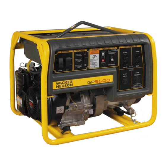
Page 30: Control Panel
GP/GPS 5600A Operation 5.11 Control Panel Ref. Description Ref. Description Engine Switch GFCI test button Auto Idle Switch GFCI reset button Twist-lock receptacle - 120V Twist-lock receptacle - 120/240V Main Circuit Breaker Ignition Switch (GPS only) Voltage Selector Switch 20A circuit breaker (CAN only) Duplex receptacle - 120V 30A circuit breaker (CAN only) -
Page 31: Ground Fault Circuit Interrupter (Gfci)
Operation GP/GPS 5600A 5.12 Ground Fault Circuit Interrupter (GFCI) The GFCI should be tested for proper operations every time the generator is used. Normal operating state - sensing device green LED is “ON” and circuit breaker is at “ON” position. 5.12.1 Press “TEST”... -
Page 32: Twist Lock Receptacles
GP/GPS 5600A Operation 5.13 Twist Lock Receptacles Twist-lock receptacles (c, j) are used at the 120V Amp and 120/240V outlets. These receptacles are protected by the GFCI. To attach a power cord to a twist-lock receptacle, insert plug into receptacle and turn it clockwise to lock it in place. 5.14 Engine Auto Idle The auto idle switch (b) automatically reduces engine speed approximately 7 seconds after all appliances or tools attached to the... -
Page 33: Voltage Selection
Operation GP/GPS 5600A 5.16 Voltage Selection The voltage selector switch (e) allows the generator to operate in either single (120V) or dual voltage (120/240V) mode. In single-voltage mode, use only the 120V twist-lock (c) and duplex receptacles (f1, f2). The full rated power of the generator is shared between the three receptacles. -
Page 34: Before Starting
GP/GPS 5600A Operation 5.17 Before Starting 5.17.1 Read and understand the safety and operating labels and instructions at the beginning of this manual. 5.17.2 Inspect the generator for any signs of damage which may affect operation or pose a safety hazard. 5.17.3 Check: •... -
Page 35: To Start
Operation GP/GPS 5600A 5.18 To Start Before starting, be sure you read and understand all the safety and operating instructions in this manual. 5.18.1 Disconnect all loads from the generator and place the main circuit breaker switch in the OFF position (a2). 5.18.2 Set the auto idle switch to “OFF”... -
Page 36: To Stop
GP/GPS 5600A Operation 5.19 To Stop 5.19.1 Turn off and disconnect all tools and appliances attached to the generator. 5.19.2 Place the main circuit breaker in the OFF position (a2). 5.19.3 Turn the engine switch to “OFF” (b2). 5.19.4 Close the fuel valve (d2). Note: To stop the engine quickly in an emergency, turn or press the engine switch to “OFF”... -
Page 37: Maintenance
Maintenance GP/GPS 5600A Maintenance Engine Maintenance The chart below lists basic machine and engine maintenance. Refer to your Wacker Engine Operator’s Manual for additional information on engine maintenance. Periodic Maintenance Schedule Daily After Every Every Every before first starting 20 hrs. hrs. -
Page 38: Engine Oil
GP/GPS 5600A Maintenance Engine Oil 6.3.1 Drain the oil while the engine is still warm. 6.3.2 Remove the oil filler plug (a) and the drain plug (b) to drain the oil. Note: In the interests of environmental protection, place a plastic sheet and a container under the machine to collect any liquid that drains off. -
Page 39: Servicing Air Cleaner
Maintenance GP/GPS 5600A Servicing Air Cleaner Service the air cleaner frequently to prevent carburetor malfunction. NOTICE: NEVER run the engine without the air cleaner. Severe engine damage will occur. NEVER use gasoline or other types of low flash-point solvents for cleaning the air cleaner. -
Page 40: Spark Plug
GP/GPS 5600A Maintenance Spark Plug Clean or replace the spark plug as needed to ensure proper operation. Refer to your engine operator’s manual. The muffler becomes very hot during operation and remains hot for a while after stopping the engine. Do not touch the muffler while it is hot. WARNING Note: Refer to section Technical Data for the recommended spark plug type and the electrode gap setting. -
Page 41: Cleaning The Sediment Cup
Maintenance GP/GPS 5600A Cleaning the Sediment Cup 6.6.1 Turn the fuel valve off. 6.6.2 Remove the sediment cup (a) and the O-ring (b). 6.6.3 Wash both thoroughly in a nonflammable solvent. Dry and reinstall them. 6.6.4 Turn the fuel valve on and check for leaks. wc_gr000029... -
Page 42: Carburetor Adjustment
GP/GPS 5600A Maintenance Carburetor Adjustment 6.7.1 Start the engine and allow it to warm up to operating temperature. Set the pilot screw (a) two turns out. See Note. 6.7.2 6.7.3 With the engine idling, turn the pilot screw (a) in or out to the setting that produces the highest rpm. -
Page 43: Storage
Maintenance GP/GPS 5600A Storage Before storing the generator for a long period of time: 6.9.1 Close the fuel valve and remove and empty the sediment cup or fuel strainer. 6.9.2 Disconnect the fuel line from the carburetor. Place the open end of the fuel line into a suitable container and open the fuel valve to drain the fuel from the tank. -
Page 44: Troubleshooting
GP/GPS 5600A Maintenance 6.11 Troubleshooting Problem / Symptom Reason / Remedy If engine doesn't start, check • Engine switch is on “Start”. that: • Fuel valves under fuel tank and on engine are open. • Fuel tank has fuel. • Choke lever is in correct position. Choke should be closed when starting a cold engine. - Page 45 Maintenance GP/GPS 5600A Notes:...
-
Page 46: Electrical Schematic
GP/GPS 5600A Maintenance 6.13 Electrical Schematic Ref. Description Ref. Description Generator Wacker Engine Control box Honda Engine Electric start engines (GPS) Ref. Description Ref. Description Main stator winding 1 Engine ON / OFF switch Main stator winding 2 Rectifier Auto idle unit Rotor winding/brushes Main circuit breaker Secondary (excitation) winding... - Page 47 Maintenance GP/GPS 5600A...
-
Page 48: Electrical Schematic (Can Models Only)
GP/GPS 5600A Maintenance 6.14 Electrical Schematic (CAN models only) Ref. Description Ref. Description Generator Wacker Engine Control box Honda Engine Electric start engines (GPS) Ref. Description Ref. Description Main stator winding 1 Rectifier Main stator winding 2 Rotor winding/brushes Auto idle unit Secondary (excitation) winding Main circuit breaker DC winding... - Page 49 Maintenance GP/GPS 5600A...
-
Page 50: Engine Schematic
GP/GPS 5600A Maintenance 6.15 Engine Schematic Ref. Description Ref. Description Generator Wacker Engine Control box Honda Engine Electric start engines (GPS) Ref. Description Ref. Description Idle solenoid Solenoid (GPS only) Fuel cut solenoid Starter (GPS only) Oil alert module Charging coil (GPS only) Oil level switch Battery (GPS only) Coil... - Page 51 Maintenance GP/GPS 5600A...
- Page 52 Wacker Construction Equipment AG · Preußenstraße 41 · D-80809 München · Tel.: +49-(0)89-3 54 02 - 0 · Fax: +49 - (0)89-3 54 02-3 90 Wacker Corporation · P.O. Box 9007 · Menomonee Falls, WI 53052-9007 · Tel. : (262) 255-0500 · Fax: (262) 255-0550 · Tel. : (800) 770-0957 Wacker Asia Pacific Operations ·...
Need help?
Do you have a question about the GP 5600A and is the answer not in the manual?
Questions and answers