Wacker Neuson GP 5600A Operator's Manual
Hide thumbs
Also See for GP 5600A:
- Operator's manual (52 pages) ,
- Repair manual (130 pages) ,
- Operator's manual (240 pages)

Related Manuals for Wacker Neuson GP 5600A


Summary of Contents for Wacker Neuson GP 5600A
- Page 1 Operator’s Manual Portable Generator GP 5600A GPS 5600A 5000192945 0511...
- Page 2 Copyright notice © Copyright 2011 by Wacker Neuson Production Americas LLC All rights, including copying and distribution rights, are reserved. This publication may be photocopied by the original purchaser of the machine. Any other type of reproduction is prohibited without express written permission from Wacker Neuson Production Americas LLC.
- Page 3 Refer to the separate Repair Manual for detailed instructions on servicing and repairing the machine. If you are missing any of these documents, please contact Wacker Neuson to order a replacement or visit www.wackerneuson.com. When ordering parts or requesting service information, be prepared to provide the machine model number, item number, revision number, and serial number.
- Page 4 Serious injury hazards to the operator and persons in the work area Permanent damage to the machine which will not be covered under warranty Contact your Wacker Neuson dealer immediately if you have questions about approved or unapproved parts, attachments, or modifications.
-
Page 5: Table Of Contents
GP / GPS 5600A Table of Contents Foreword Safety Information Signal Words Used in this Manual ............7 Machine Description and Intended Use ..........8 Operating Safety .................. 9 Operator Safety while Using Internal Combustion Engines ....12 Service Safety ..................13 Labels Label Locations .................. -
Page 6: Schematics
Emission Control Systems Information and Warranty Emission Control System Background Information ......49 Limited Defect Warranty for Exhaust Emission Control System ..50 Limited Defect Warranty for Wacker Neuson Evaporative Emission Control Systems ..............51 California Evaporative Emission Control Warranty Statement ... 54 Limited Defect Warranty for Exhaust Emission Control System .. -
Page 7: Safety Information
GP/GPS 5600A Safety Information Safety Information Signal Words Used in this Manual This manual contains DANGER, WARNING, CAUTION, NOTICE, and NOTE signal words which must be followed to reduce the possibility of personal injury, damage to the equipment, or improper service. This is the safety alert symbol. -
Page 8: Machine Description And Intended Use
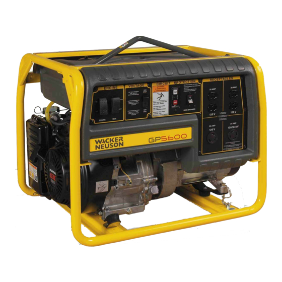
Safety Information GP/GPS 5600A Machine Description and Intended Use This machine is a portable electric power source. The Wacker Neuson Portable Generator consists of a tubular steel frame surrounding a fuel tank, a gasoline engine, a control panel, and an electric alternator. -
Page 9: Operating Safety
GP/GPS 5600A Safety Information Personal injury from improper lifting techniques To protect yourself and others, make sure you thoroughly read and understand the safety information presented in this manual before operating the machine. Operating Safety DANGER Carbon monoxide. Using a generator indoors CAN KILL YOU IN MINUTES. Generator exhaust contains carbon monoxide (CO). - Page 10 Safety Information GP/GPS 5600A Improper connection of generator to a building’s electrical system can allow electrical current from the generator to backfeed into utility lines. This may result in electrocution of utility workers, fire, or explosion. Connections to a building’s electrical system must be made by a qualified electrician and comply with all applicable laws and electrical codes.
- Page 11 GP/GPS 5600A Safety Information 1.3.15 ALWAYS keep the machine at least one meter (three feet) away from structures, buildings, and other equipment during use. 1.3.16 ALWAYS keep the area immediately surrounding and underneath the machine clean, neat, and free of debris and combustible materials. Make sure that the area overhead is clear of debris that could fall onto or into the machine or exhaust compartment.
-
Page 12: Operator Safety While Using Internal Combustion Engines
Safety Information GP/GPS 5600A Operator Safety while Using Internal Combustion Engines WARNING Internal combustion engines present special hazards during operation and fueling. Failure to follow the warnings and safety standards could result in severe injury or death. Read and follow the warning instructions in the engine owner’s manual and the safety guidelines below. -
Page 13: Service Safety
GP/GPS 5600A Safety Information Generator vibration Generators vibrate in normal use. During and after the use of the generator, inspect the generator as well as extension cords and power supply cords connected to it for damage from vibration. • Have damaged items repaired or replaced as necessary. •... - Page 14 Leaking fuel and fumes are extremely explosive. 1.5.13 When replacement parts are required for this machine, use only Wacker Neuson replacement parts or those parts equivalent to the original in all types of specifications, such as physical dimensions, type, strength, and material.
-
Page 15: Labels
GP/GPS 5600A Labels Labels Label Locations wc_gr003142 wc_si000558gb.fm... -
Page 16: Label Meanings
Labels GP/GPS 5600A Label Meanings Wacker Neuson machines use international pictorial labels where needed. These labels are described below. Engine Choke Control WARNING! Hot surface! — DANGER! Read the Operator’s Manual. No sparks, flames, or burning objects near the machine. - Page 17 GP/GPS 5600A Labels — — CAUTION! Use only clean, filtered gasoline fuel. Check the fuel level. — Open the fuel flow valve. — Close the choke. — Turn the engine switch to the ON position. — Pull the rewind starter. —...
- Page 18 Labels GP/GPS 5600A — Close the fuel flow valve. — DANGER Using a generator indoors CAN KILL YOU IN MINUTES. Generator exhaust contains carbon monoxide. This is a poison you cannot see or smell. — NEVER use inside a home or garage, EVEN IF doors and windows are open.
- Page 19 GP/GPS 5600A Labels WARNING Operation of this equipment may create sparks that can start fires around dry vegetation. A spark arrester may be required. The operator should contact local fire agencies for laws or regulations relating to fire prevention requirements. A nameplate listing the model number, item number, revision number, and serial number is attached to each unit.
- Page 20 Labels GP/GPS 5600A Notes: wc_si000558gb.fm...
-
Page 21: Operation
3.1.2 Check the machine and its components for damage. If there is visible damage, do not operate the machine! Contact your Wacker Neuson dealer immediately for assistance. 3.1.3 Take inventory of all items included with the machine and verify that all loose components and fasteners are accounted for. -
Page 22: Recommended Fuel
Before using an oxygenated fuel, confirm the fuel's contents. Some states / Provinces require this information to be posted on the fuel pump. The following are Wacker Neuson approved percentages of oxygenates: - (ethyl or grain alcohol) 10% by volume. You may use... -
Page 23: Determining Power Requirements
Check with your nearest Wacker Neuson dealer, or contact the manufacturer or dealer of the tool or appliance, with questions regarding its power requirements. -
Page 24: Installation
Operation GP/GPS 5600A Installation Place the generator in an area where it will not be exposed to rain, snow, or direct sunlight. Make sure it is positioned on firm, level ground, so it will not slide or shift. Position the engine exhaust away from areas where people may be present. -
Page 25: Battery Tray Installation (Gps Only)
GP/GPS 5600A Operation Battery Tray Installation (GPS only) 3.6.1 Align the holes found in the battery tray (a) to the holes on the frame cross-member 3.6.2 Insert M8 x 14 screws (b) through the tray then through the holes of the cross-member. -
Page 26: Wheel Kit
Operation GP/GPS 5600A Wheel Kit The wheel kit (Part No. 0161308) is a standard item on Item Number 0620012, 0620015, 0620043 and 0620046 only. It is available as an option on all other models. 3.7.1 Hoist the generator, and align the axle (c) with the lower cross-member of frame. - Page 27 GP/GPS 5600A Operation wc_tx000789gb.fm...
-
Page 28: Generator Derating
Operation GP/GPS 5600A Generator Derating All generators are subject to derating for altitude and temperature. Internal combustion engines, unless modified, run less efficiently at higher altitudes due to the reduction of air pressure. This translates into a lack of power and thus reduction in generator output. Temperature affects both engine and generator performance. -
Page 29: Grounding The Generator
GP/GPS 5600A Operation Grounding the Generator Location A ground connection (a) is located on the generator frame. wc_gr000544 Function This ground connection is used for electrically grounding the generator when necessary to comply with the National Electrical Code and other federal, state, and local regulations. For grounding requirements in your area, consult with a qualified electrician, electrical inspector, or local agency having jurisdiction over electrical compliance. -
Page 30: Use Of Extension Cords
Operation GP/GPS 5600A 3.11 Use of Extension Cords When a long extension cord is used to connect an appliance or tool to the generator, a voltage loss occurs—the longer the cord, the greater the voltage loss. This results in less voltage being supplied to the appliance or tool and increases the amount of current draw or reduces performance. -
Page 31: Control Panel
GP/GPS 5600A Operation 3.12 Control Panel Ref. Description Ref. Description Engine Switch GFCI test button Auto Idle Switch GFCI reset button Twist-lock receptacle - 120V Twist-lock receptacle - 120/240V Main Circuit Breaker Ignition Switch (GPS only) Voltage Selector Switch 20A circuit breaker (CAN only) Duplex receptacle - 120V 30A circuit breaker (CAN only) wc_gr003143... -
Page 32: Ground Fault Interrupt (Gfi / Gfci)
Operation GP/GPS 5600A 3.13 Ground Fault Interrupt (GFI / GFCI) The GFCI should be tested for proper operations every time the generator is used. Normal operating state - sensing device green LED is “ON” and circuit breaker is at “ON” position. 3.13.1 Press “TEST”... -
Page 33: Twist-Lock Receptacles
GP/GPS 5600A Operation 3.14 Twist-Lock Receptacles Twist-lock receptacles (c, j) are used at the 120V Amp and 120/240V outlets. These receptacles are protected by the GFCI. To attach a power cord to a twist-lock receptacle, insert plug into receptacle and turn it clockwise to lock it in place. 3.15 Engine Auto Idle The auto idle switch (b) automatically reduces engine speed... -
Page 34: Voltage Selector Switch
Operation GP/GPS 5600A 3.17 Voltage Selector Switch The voltage selector switch (e) allows the generator to operate in either single (120V) or dual voltage (120/240V) mode. In single-voltage mode, use only the 120V twist-lock (c) and duplex receptacles (f1, f2). The full rated power of the generator is shared between the three receptacles. -
Page 35: Before Starting
GP/GPS 5600A Operation 3.18 Before Starting DANGER Carbon monoxide. Using a generator indoors CAN KILL YOU IN MINUTES. Generator exhaust contains carbon monoxide (CO). This is a poison you cannot see or smell. If you can smell the generator exhaust, you are breathing CO. But even if you cannot smell the exhaust, you could be breathing CO. -
Page 36: Starting
Operation GP/GPS 5600A 3.19 Starting Before starting, be sure you read and understand all the safety and operating instructions in this manual. 3.19.1 Ensure that the generator is properly installed in an outdoor location. See Sections Installation and Operator Safety while using Internal Combustion Engines for installation warnings and safety guidelines. -
Page 37: Stopping
GP/GPS 5600A Operation 3.20 Stopping 3.20.1 Turn off and disconnect all tools and appliances attached to the generator. 3.20.2 Place the main circuit breaker in the OFF position (a2). 3.20.3 Turn the engine switch to “OFF” (b2). 3.20.4 Close the fuel valve (d2). Note: To stop the engine quickly in an emergency, turn or press the engine switch to “OFF”... -
Page 38: Maintenance
WACKER NEUSON. The use of service parts that are not equivalent in performance and durability to authorized parts may impair the effectiveness of the emission control system and may have a bearing on the outcome of a warranty claim. -
Page 39: Engine Oil
GP/GPS 5600A Maintenance Engine Oil 4.3.1 Drain the oil while the engine is still warm. 4.3.2 Remove the oil filler plug (a) and the drain plug (b) to drain the oil. Note: In the interests of environmental protection, place a plastic sheet and a container under the machine to collect any liquid that drains off. -
Page 40: Servicing The Air Cleaner
Maintenance GP/GPS 5600A Servicing the Air Cleaner Service the air cleaner frequently to prevent carburetor malfunction. NOTICE: NEVER run the engine without the air cleaner. Severe engine damage will occur. NEVER use gasoline or other types of low flash-point solvents for cleaning the air cleaner. -
Page 41: Spark Plug
GP/GPS 5600A Maintenance Spark Plug Clean or replace the spark plug as needed to ensure proper operation. Refer to your engine operator’s manual. The muffler becomes very hot during operation and remains hot for a while after stopping the engine. Do not touch the muffler while it is hot. WARNING Note: Refer to section “Technical Data”... -
Page 42: Cleaning The Sediment Cup
Maintenance GP/GPS 5600A Cleaning the Sediment Cup 4.6.1 Turn the fuel valve off. 4.6.2 Remove the sediment cup (a) and the O-ring (b). 4.6.3 Wash both thoroughly in a nonflammable solvent. Dry and reinstall them. 4.6.4 Turn the fuel valve on and check for leaks. Engine Speed Generators require a fixed engine speed to maintain the correct voltage. -
Page 43: Long-Term Storage
GP/GPS 5600A Maintenance Long-Term Storage Before storing the generator for a long period of time: 4.8.1 Close the fuel valve and remove and empty the sediment cup or fuel strainer. 4.8.2 Disconnect the fuel line from the carburetor. Place the open end of the fuel line into a suitable container and open the fuel valve to drain the fuel from the tank. -
Page 44: Troubleshooting
Maintenance GP/GPS 5600A 4.10 Troubleshooting Problem / Symptom Reason / Remedy If engine doesn't start, check • Engine switch is on “Start”. that: • Fuel valves under fuel tank and on engine are open. • Fuel tank has fuel. • Choke lever is in correct position. Choke should be closed when starting a cold engine. -
Page 45: Technical Data
GP/GPS 5600A Technical Data Technical Data Generator Item No. GP 5600A GP 5600A GPS 5600A with wheel kit Generator Maximum Output 5600 Continuous Output 5000 Type Dual voltage, single phase, Auto voltage regulator system AC Voltages Avail- volts 120 / 240... -
Page 46: Engine
GP/GPS 5600A Engine Engine Power Rating Net power rating per SAE J1349. Actual power output may vary due to conditions of specific use. Item No. GP 5600A GPS 5600A Engine Engine type Single cylinder, 4-cycle, air-cooled, gasoline engine Engine make... - Page 47 GP/GPS 5600A Technical Data Notes: wc_td000240gb.fm...
- Page 48 Technical Data GP/GPS 5600A wc_td000240gb.fm...
-
Page 49: Emission Control Systems Information And Warranty
Carbon monoxide does not react in the same way, but it is toxic. Wacker Neuson utilizes lean carburetor settings and other systems to reduce the emissions of carbon monoxide, oxides of nitrogen, and hydrocarbons. Evaporative Emissions... -
Page 50: Limited Defect Warranty For Exhaust Emission Control System
Tampering and Altering Tampering with or altering the emission control system may increase emissions beyond the legal limit. If evidence of tampering is found, Wacker Neuson may deny a warranty claim. Among those acts that constitute tampering are: Removing or altering of any part of the air intake, fuel, or exhaust systems. -
Page 51: Limited Defect Warranty For Wacker Neuson Evaporative Emission Control Systems
Any implied warranties are limited to the duration of this written warranty. What is covered Wacker Neuson recommends the use of genuine Wacker Neuson parts, or the equivalent, whenever maintenance is performed. The use of replacement parts not equivalent to the original parts may impair the effectiveness of the engine/ equipment emission controls systems. - Page 52 Wacker Neuson dealer/ service center. The engine/equipment must be presented to an authorized Wacker Neuson dealer/ service center as soon as a problem exists. Contact Wacker Neuson Product wc_tx001772gb.fm...
- Page 53 For owners located more than 100 miles from an authorized dealer/service center (excluding the states with high-altitude areas as identified in 40 CFR Part 1068, Appendix III), Wacker Neuson will pay for pre-approved shipping costs to and from an authorized Wacker Neuson dealer/service center.
-
Page 54: California Evaporative Emission Control Warranty Statement
This EECS is warranted for two years from the initial date of purchase. If any evaporative emission-related part on your equipment is defective, the part will be repaired or replaced by Wacker Neuson Corporation at no charge to you. The owner shall not be charged for diagnostic labor that leads to determination that a warranted part is in fact defective, provided that such diagnostic work is performed at a Wacker Neuson Corporation authorized service center. -
Page 55: Limited Defect Warranty For Exhaust Emission Control System
What is covered The repair or replacement of any warranted part otherwise eligible for warranty coverage may be excluded from such warranty coverage if Wacker Neuson Corporation demonstrates that the portable generator has been abused, neglected, or improperly maintained, and that such abuse, neglect, or improper maintenance was the direct cause of the need for repair or replacement of the part. -
Page 56: Schematics
Schematics GP / GPS 5600A Schematics Wire Colors Wire Colors Black Yellow Orange Green Brown Purple Blue Violet Clear Shield Pink White Gray Light blue US Machines—Electrical Schematic Ref. Description Ref. Description Generator Honda Engine Control box Electric start engines (GPS) Ref. -
Page 57: Gp / Gps 5600A
GP / GPS 5600A Schematics wc_tx001774gb.fm... -
Page 58: Csa Machines-Electrical Schematic
Schematics GP / GPS 5600A CSA Machines—Electrical Schematic Ref. Description Ref. Description Generator Honda Engine Control box Electric start engines (GPS) Ref. Description Ref. Description Main stator winding 1 Engine ON / OFF switch Main stator winding 2 Rectifier Auto idle unit Rotor winding/brushes Main circuit breaker Secondary (excitation) winding... - Page 59 GP / GPS 5600A Schematics wc_tx001774gb.fm...
-
Page 60: Engine Wiring
Schematics GP / GPS 5600A Engine Wiring Ref. Description Ref. Description Generator Honda Engine Control box Electric start engines (GPS) Ref. Description Ref. Description Idle solenoid Solenoid (GPS only) Fuel cut solenoid Starter (GPS only) Oil level sender Charging coil (GPS only) Spark plug Battery (GPS only) Coil... - Page 62 Tel. : (262) 255-0500 Fax: (262) 255-0550 Tel.: (800) 770-0957 Wacker Neuson Limited - Room 1701–03 & 1717–20, 17/F. Tower 1, Grand Century Place, 193 Prince Edward Road West, Mongkok, Kowloon, Hongkong. Tel: (852) 3605 5360, Fax: (852) 2758 0032...
Need help?
Do you have a question about the GP 5600A and is the answer not in the manual?
Questions and answers