Table of Contents
Advertisement
Quick Links
Advertisement
Table of Contents

Related Manuals for Wacker Neuson G 50


Summary of Contents for Wacker Neuson G 50
- Page 1 Operator’s Manual Mobile Generator G 50 5000189846 0911...
- Page 2 Wacker Neuson Production Americas LLC. Any type of reproduction or distribution not authorized by Wacker Neuson Production Americas LLC represents an infringement of valid copyrights. Violators will be prosecuted.
-
Page 3: Foreword
Refer to the separate Repair Manual for detailed instructions on servicing and repairing the machine. If you are missing any of these documents, please contact Wacker Neuson to order a replacement or visit www.wackerneuson.com. When ordering parts or requesting service information, be prepared to provide the machine model number, item number, revision number, and serial number. - Page 4 Serious injury hazards to the operator and persons in the work area Permanent damage to the machine which will not be covered under warranty Contact your Wacker Neuson dealer immediately if you have questions about approved or unapproved parts, attachments, or modifications.
-
Page 5: Table Of Contents
G 50 Table of Contents Foreword Safety Information Signal Words Used in this Manual ............9 Machine Description and Intended Use ..........10 Operating Safety ................12 Service Safety ..................14 Operator Safety while using Internal Combustion Engines ....16 Towing Safety .................. - Page 6 Table of Contents G 50 4.13 Engine Start Switch ................43 4.14 Voltage Adjustment Rheostat ..............43 4.15 Warning Light ..................43 4.16 Connection Lugs .................44 4.17 Grounding the Generator ..............45 4.18 Convenience Receptacles ..............46 4.19 Remote Run Terminal Block ...............46 4.20 Panel Door Interlock Switch ..............46 4.21...
- Page 7 G 50 Table of Contents 6.10 Camlocks .................... 71 6.11 Containment System ................72 6.12 Wiring Diagram (Factory-Installed Options) ........73 6.13 Wiring Diagram Components (Factory-Installed Options) ....74 Maintenance Periodic Maintenance Schedule ............75 New Machines ..................76 Resetting the Periodic Maintenance Timer ........76 Electronic Control Unit (ECU) .............
- Page 8 Table of Contents G 50 wc_bo5000189846_05TOC.fm...
-
Page 9: Safety Information
G 50 Safety Information Safety Information Signal Words Used in this Manual This manual contains DANGER, WARNING, CAUTION, NOTICE, and NOTE signal words which must be followed to reduce the possibility of personal injury, damage to the equipment, or improper service. -
Page 10: Machine Description And Intended Use
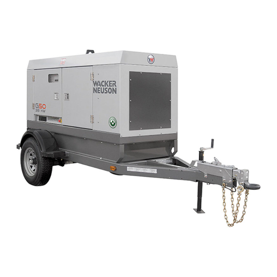
Safety Information G 50 Machine Description and Intended Use This machine is a mobile electric power source. The Wacker Neuson Mobile Generator consists of a trailer-mounted cabinet containing an electric alternator, a fuel tank, and a diesel engine. A control panel, receptacles, and connection lugs are provided on the side of the cabinet. - Page 11 This machine is built with user safety in mind; however, like any electrical device it can present serious hazards if improperly operated and serviced. Follow instructions carefully! Should questions arise during operation or service of this equipment, contact Wacker Neuson Corporation. wc_si000533gb.fm...
-
Page 12: Operating Safety
Safety Information G 50 Operating Safety Familiarity and proper training are required for the safe operation of the machine. Machines operated improperly or by untrained personnel can be dangerous. Read the operating instructions WARNING contained in both this manual and the engine manual and familiarize yourself with the location and proper use of all controls. - Page 13 G 50 Safety Information 1.3.10 Do not start a machine in need of repair. 1.3.11 Use the emergency stop button only in an actual emergency. Do not restart the engine until the cause of the trouble has been determined and fixed.
-
Page 14: Service Safety
Safety Information G 50 Service Safety A poorly maintained machine can become a safety hazard! In order for the machine to operate safely and properly over a long period of time, periodic maintenance and occasional repairs are necessary. WARNING Personal Protective Equipment (PPE) - Page 15 G 50 Safety Information 1.4.6 Do not allow untrained personnel to service this equipment. Only trained electrical technicians should be allowed to service the electrical components of this equipment. 1.4.7 Do not modify the machine without the express written approval of the manufacturer.
-
Page 16: Operator Safety While Using Internal Combustion Engines
Safety Information G 50 Operator Safety while using Internal Combustion Engines WARNING Internal combustion engines present special hazards during operation and fueling. Failure to follow the warnings and safety standards could result in severe injury or death. Read and follow the warning instructions in the engine owner’s manual and the safety guidelines below. -
Page 17: Towing Safety
National Highway Traffic Safety Administration (NHTSA) in addition to notifying Wacker Neuson Corporation. If NHTSA receives similar complaints, it may open an investigation; and if it finds that a safety defect exists in a group of vehicles, it may order a recall and remedy campaign. -
Page 18: Labels
Labels G 50 Labels Label Locations WARNING WARNING WARNUNG WARNUNG ADVERTENCIA ADVERTENCIA AVERTISSEMENT AVERTISSEMENT WARNING WARNING WARNUNG WARNUNG ADVERTENCIA ADVERTENCIA AVERTISSEMENT AVERTISSEMENT 114885 114885 wc_gr007670 wc_si000520gb.fm... - Page 19 G 50 Labels E UU SS TT wc_gr007671 wc_si000520gb.fm...
-
Page 20: Label Meanings
Labels G 50 Label Meanings WARNING! Pressurized contents. Do not open when hot! WARNING! Lock doors. Access can cause electric shock or injury. NOTICE Never change switch position with engine run- ning. Results in damage to machine. WARNING! Electric shock can cause serious injury or death. - Page 21 G 50 Labels WARNING! To prevent hearing loss, wear hearing protection. Hand injury if entangled in moving belt. Rotating machinery! Do not reach inside with engine running. WARNING! Hot surface CAUTION! Avoid spraying water into generator. WARNING! Hot surface WARNING Electric shock at cooling fins.
- Page 22 Labels G 50 WARNING! Read and understand the supplied Operator’s Manual before operating the machine. Failure to do so increases the risk of injury to yourself and others. WARNING! To reduce the risk of electrical shock and arc flash, read the Operator’s Manual. Improper con- nection of the generator to a building’s electrical...
- Page 23 G 50 Labels WARNING! To prevent hearing loss, wear hearing protection when operating the machine. WARNING! Pressurized contents. Do not open when hot! WARNING! Hand injury if entangled in moving belt. WARNING! Rotating machinery! Do not reach inside machine with engine running.
- Page 24 Labels G 50 Tie-down point Electrical ground wc_si000520gb.fm...
- Page 25 G 50 Labels Operator’s Manual must be stored on machine. Replacement Operator’s Manual can be ordered through your local Wacker Neuson distributor. Remote start operation. Read Operator’s Manual for instructions. Drain containment system. Operating the main circuit breaker supplies or interrupts power to the customer connection lugs.
- Page 26 Labels G 50 Generator and receptacle wiring Engine wiring Protecting Our Environment Fluid containment system Diagnostic menu navigation wc_si000520gb.fm...
- Page 27 G 50 Labels A nameplate listing the model number, item num- ber, revision number, and serial number is attached to each unit. Please record the informa- tion found on this nameplate so it will be available should the nameplate become lost or damaged.
- Page 28 Labels G 50 (Camlock models only) WARNING! Electric shock and arc flash can cause serious injury or death. wc_si000520gb.fm...
-
Page 29: Lifting And Transporting
G 50 Lifting and Transporting Lifting and Transporting Lifting the Machine A central lifting eye is located at the top of the generator and is attached to a lifting frame inside the housing. Crushing / machine damage hazard. Make sure the lifting devices have sufficient capacity to lift the unit safely. - Page 30 Lifting and Transporting G 50 NOTICE: When towing, maintain extra space between vehicles and avoid soft shoulders, curbs and sudden lane changes. If you have not pulled a trailer before, practice turning, stopping, and backing up in an area away from heavy traffic.
- Page 31 G 50 Lifting and Transporting Notes: wc_tx001580gb.fm...
-
Page 32: Operation
4.0.2 Check the machine and its components for damage. If there is visible damage, do not operate the machine! Contact your Wacker Neuson dealer immediately for assistance. 4.0.3 Take inventory of all items included with the machine and verify that all loose components and fasteners are accounted for. -
Page 33: Refueling The Machine
G 50 Operation Refueling the Machine Requirements • Machine shut down • Engine cool • Machine/fuel tank level with the ground • Fresh, clean fuel supply Procedure Perform the procedure below to refuel the machine. WARNING Fire hazard. Fuel and its vapors are extremely flammable. Burning fuel can cause severe burns. -
Page 34: Control Panel
Operation G 50 Control Panel DIAGNOSTICS DIAGNOSTICS DIAGNOSEN DIAGNOSEN DIAGNOSTICOS DIAGNOSTICOS DIAGNOSTICS DIAGNOSTICS Ø APAGADO APAGADO ARRET ARRET DIAGNOSTICS REMOTE START REMOTE START START / RUN START / RUN DIAGNOSEN FERNSTART FERNSTART START / LAUFEN START / LAUFEN DIAGNOSTICOS ARRANQUE REMOTO... - Page 35 G 50 Operation Ref. Description Ref. Description Main circuit breaker Remote run terminal block Voltage adjustment rheostat Emergency stop switch Pre-alarm/shutdown LED Interlock switch LCD panel Customer connection terminal lugs Engine start switch Ground connection Keypad Bond bar Circuit breaker...
-
Page 36: Voltage Selector Switch
Operation G 50 Voltage Selector Switch See Graphic: wc_gr001682 The voltage selector switch is located in a separate enclosure on the generator on the opposite side of the machine. The selector switch is a three-position switch which mechanically changes the connections between the generator output leads and the terminal lugs on the generator. -
Page 37: Emergency Stop Switch
G 50 Operation Emergency Stop Switch See Graphic: wc_gr006062 The emergency stop switch (p) is the red button located below the receptacle panel and can be accessed with the panel doors closed. Activate the emergency stop switch by pushing the red button in. -
Page 38: Generator Monitoring
Operation G 50 Generator Monitoring Generator information is displayed on the top line of the LCD panel and is scrolled continuously while the generator is operating, to show the voltage, amperage and frequency of each phase. Volts “V”- Displays the AC output voltage being produced by the generator. -
Page 39: Engine Monitoring
G 50 Operation Engine Monitoring With the engine start switch set to “RUN/START” or “REMOTE START”, engine information will be continuously displayed on the bottom line of the LCD panel. —Displays engine oil pressure. The gauge registers oil pressure between 0–100 psi. Normal operating pressure is between 60–80 psi. -
Page 40: Engine Shutdown Faults
Operation G 50 Engine shutdown faults The Engine Control Module (ECM) continuously monitors vital engine functions for seven fault conditions. When a fault condition occurs, the engine will shut down and the LCD panel will display the fault causing the shutdown. To reset the ECM and resume operation, return the engine start switch manually to off “O”. -
Page 41: Current Overload Fault
G 50 Operation 4.10 Current Overload Fault Along with engine functions, the ECM continuously monitors the current load in each phase. The values for current overload are programmed into the ECM at the factory and are different for each generator size. -
Page 42: Main Line Circuit Breaker
Operation G 50 4.12 Main Line Circuit Breaker See Graphic: wc_gr005866 The main line circuit breaker (a) is located on the control panel. In the off “O” position, this breaker interrupts power from the selector switch to the terminal lugs at the bottom of the generator panel. -
Page 43: Engine Start Switch
G 50 Operation 4.13 Engine Start Switch See Graphic: wc_gr005866 The engine start switch (f) is a three-position switch: “REMOTE START”, off “O”, and “START/RUN”. The “REMOTE START” position is the normal setting used when using the generator as a back-up power supply connected to a remote switch. -
Page 44: Connection Lugs
Operation G 50 4.16 Connection Lugs See Graphic: wc_gr005864 The customer connection lugs (r) are located on left at the bottom of the panel behind a hinged door. The lugs provide connection points for attachment of outside loads. A large label like the one shown in section Terminal Connections is attached to the inside of the terminal door. -
Page 45: Grounding The Generator
G 50 Operation 4.17 Grounding the Generator Location A ground connection is located at the customer connection terminal lugs. wc_gr008288 Function This ground connection is used for electrically grounding the generator when necessary to comply with the National Electrical Code and other federal, state, and local regulations. For grounding... -
Page 46: Convenience Receptacles
Operation G 50 4.18 Convenience Receptacles See Graphic: wc_gr005864 The generator is equipped with two 120V/240V twist lock receptacles (l) rated at 50A, and one 120V/240V twist lock receptacle (m) rated at 30A. The two 120V duplex receptacles (n) are equipped with ground fault interrupts (GFI). -
Page 47: Terminal Connections
G 50 Operation 4.21 Terminal Connections ALL CONNECTIONS TO THE TERMINALS MUST BE MADE BY A TRAINED ELECTRICIAN. BACKFEED FROM THE GENERATOR INTO THE UTILITY’S DISTRIBUTION SYSTEM CAN CAUSE A SERIOUS INJURY OR DEATH TO UTILITY WORKERS! WARNING Improper connection of generator to a building’s electrical system can allow electrical current from the generator to backfeed into utility lines. -
Page 48: Before Starting
Operation G 50 4.22 Before Starting Before putting the generator into service, review each item on the following checklist. Because generators are often run for long periods of time unattended, it is important to make sure that the unit is set up properly to reduce possible problems. - Page 49 G 50 Operation When using the generator as a stand-by or substitute power supply, make sure the voltage and phase rotation of the line connections match those of the utility lines or of any other power source normally WARNING used. Failure to match phase rotation and voltage may cause equipment connected to the generator to operate incorrectly! This could create unsafe operating conditions.
-
Page 50: Table Of Contents G
Operation G 50 wc_gr001677 Ø APAGADO APAGADO ARRET ARRET DIAGNOSTICS REMOTE START REMOTE START START / RUN START / RUN DIAGNOSEN START / LAUFEN START / LAUFEN FERNSTART FERNSTART DIAGNOSTICOS ARRANQUE REMOTO ARRANQUE REMOTO ARRANQUE / MARCHA ARRANQUE / MARCHA... -
Page 51: Running The Generator
G 50 Operation 4.24 Running the Generator See Graphic: wc_gr005866 Leave the engine start switch (f) in the “START/RUN” position while the generator is operating. If the generator was started using a remote switch, leave engine start switch in the “REMOTE START” position. -
Page 52: Engine Power Correction Factors
Operation G 50 4.25 Engine Power Correction Factors Performance data conditions Performance data on John Deere engines are measured at the following standard conditions: • 744 mm (29.31 in.) of mercury dry air pressure • 0% relative humidity • 25°C (77°F) air intake temperature •... -
Page 53: Automatic/Remote Start-Up
G 50 Operation 4.28 Automatic/Remote Start-Up See graphic: wc_gr005938 In the “REMOTE START” position the generator can be started remotely, either through a transfer switch or some other type of remote start switch. “REMOTE START” is the normal setting when using the generator as a stand-by power supply. -
Page 54: Remote/Transfer Switch
Operation G 50 4.29 Remote/Transfer Switch When the generator is used as a stand-by power supply, it must be equipped with a device which isolates it from the utility’s distribution system. WARNING Failure to isolate the generator from the utility’s electrical... -
Page 55: Using The Lcd Panel And Keypad
Using the LCD Panel and Keypad Mobile Generator Using the LCD Panel and Keypad See graphic: wc_gr005938, wc_gr006064 During normal operation, the LCD panel (e) displays current information on machine performance and operating status. The keypad (g) provides access to additional monitoring functions through a series of menus displayed on the LCD panel. -
Page 56: Navigating The Menus
Mobile Generator Using the LCD Panel and Keypad Navigating the Menus The label pictured below is a navigational aid to access the various diagnostic menus programmed into the LCD. See the accompanying table for information about the menu items. Metering Engine DIAGNOSTIC MENU Metering... - Page 57 Using the LCD Panel and Keypad Mobile Generator Menu Item Description Menu Item Description Alarm Config Alarm configuration J1939 Active DTC Diagnostic Trouble Codes Alarm Configuration J1939 Data Alarms J1939 Engine Config Engine configuration Alarm–Status J1939 Previous DTC Diagnostic Trouble Codes Amps Kilovolt-amps...
-
Page 58: Entering Passwords
Note: The default password is OP and is set by the factory. Contact your Wacker Neuson dealer if you need to have the password reset. Follow the steps below to enter a password. -
Page 59: Adjusting Screen Contrast
Using the LCD Panel and Keypad Mobile Generator Adjusting Screen Contrast The display contrast of the LCD panel can be adjusted to suit the operator’s preference, or for increased visibility in jobsites with low or bright ambient light. 5.3.1 To access the main menu, press the right arrow button (1) on the keypad (g). -
Page 60: Setting The Time Or Date
Mobile Generator Using the LCD Panel and Keypad Setting the Time or Date See graphic: wc_gr005938 The control module features a clock powered by a separate battery. Follow the steps below to change the time or date. 5.4.1 To access the main menu, press the right arrow button (1) on the keypad (g). -
Page 61: Changing User Preferences
Using the LCD Panel and Keypad Mobile Generator Changing User Preferences Changing Display Units The LCD panel can be configured by the operator to display system information in either metric units or English units. 5.5.1 To access the main menu, press the right arrow button (1) on the keypad (g). -
Page 62: Changing / Disabling Low Fuel Fault
Mobile Generator Using the LCD Panel and Keypad Changing / Disabling Low Fuel Fault See graphic: wc_gr005938 The low fuel fault value can be changed or disabled through the diagnostics menu. (For example, you may wish to reduce the value so that the machine operates for a longer period before running out of fuel.) Note: The engine will shut down if the machine runs out of fuel. -
Page 63: Changing Cooldown Time
Using the LCD Panel and Keypad Mobile Generator Changing Cooldown Time See graphic: wc_gr005938 A cooldown timer activates when the machine is no longer receiving a remote run signal. This timer is factory set to zero (0) minutes. The cooldown time can be changed if desired. 5.7.1 To access the main menu, press the right arrow button (1) on the keypad (g). -
Page 64: Factory-Installed Options
This machine may be equipped with one or more of the following factory-installed options. To verify if any of these options are installed on your machine, contact Wacker Neuson Corporation at 1-800-770- 0957. A nameplate listing the Model Number, Item Number, Revision, and Serial Number is attached to each unit. -
Page 65: Electronic Governor
G 50 Factory-Installed Options Electronic Governor See Graphic: wc_gr001714, wc_gr001716 The electronic governor option consists of an electronic module (b) and an electronic actuator (d). The module senses rotation of the flywheel, then sends a signal to the electronic actuator that governs the fuel injection system. -
Page 66: Automatic Lcd Heat
Factory-Installed Options G 50 Automatic LCD Heat To improve the performance of the LCD panel in cold weather, the LCD panel control module is equipped with an LCD heater. The heater draws power from the panel control module and is active only when the panel control module is powered. -
Page 67: Low Coolant Shutdown
G 50 Factory-Installed Options Low Coolant Shutdown See Graphic: wc_gr001708 The low-coolant shutdown system consists of an electronic sensor that monitors coolant level. The sensor (a) is mounted to the radiator and wired into the ECM. The sensor probe (b) is submerged in radiator coolant. -
Page 68: Lube Level Maintainer
Factory-Installed Options G 50 Lube Level Maintainer See Graphic: wc_gr005771, wc_gr005772, wc_gr005778 The lube level maintainer system protects the engine from low oil levels by providing an additional 6-quart oil reservoir. Oil from the reservoir is gravity-fed from the oil reservoir (a) through the control valve (b) and into the engine oil pan as needed. -
Page 69: Temperature-Activated Shutters
G 50 Factory-Installed Options Temperature-Activated Shutters See Graphic: wc_gr005770, wc_gr001707 The shutters (a) are mounted to the top of the generator enclosure. The shutters are designed to keep the engine compartment warm, thus increasing engine temperature during cold weather operation. The shutters are activated through a wax-pellet actuator (b) that is connected to the generator's cooling system. -
Page 70: Extended Run Tank
Factory-Installed Options G 50 Extended Run Tank An extended run, 331-gallon fuel tank provides a 63-hour run time under a continuous full load. The long run time eliminates the need for daily refueling, saving money on fuel deliveries. The tank is fully fluid- contained and is ideal for remote or weekend running of equipment such as dewatering submersible pumps. -
Page 71: Camlocks
G 50 Factory-Installed Options 6.10 Camlocks A second optional outlet panel features camlock connectors for easy tool changes. Each connector is protected by a spring-loaded cover. Separate overcurrent protection must be provided. Do not NOTICE: exceed 400 amps per receptacle. -
Page 72: 6.11 Containment System
Factory-Installed Options G 50 6.11 Containment System See Graphic: wc_gr002647 Overspills and leaks are captured in the containment system. The containment system holds over 110% of the fluid contained in the machine. The containment system should be checked every 50 hours or 2 weeks and drained when necessary. -
Page 73: Wiring Diagram (Factory-Installed Options)
G 50 Factory-Installed Options 6.12 Wiring Diagram (Factory-Installed Options) Wire Colors Black Yellow Orange Green Brown Purple Blue Violet Clear Shield Pink White Gray Light blue wc_tx001016gb.fm... -
Page 74: Wiring Diagram Components (Factory-Installed Options)
Factory-Installed Options G 50 6.13 Wiring Diagram Components (Factory-Installed Options) See Graphic: wc_gr001868 Description Description Thermostat module Positive air shutoff solenoid actua- Terminal block Auxiliary relay terminals 1 Amp fuse Plug 1, engine sensor inputs Water level sensor Electronic control board... -
Page 75: Maintenance
G 50 Maintenance Maintenance Periodic Maintenance Schedule The table below lists basic machine and engine maintenance. Tasks designated with check marks may be performed by the operator. Tasks designated with square bullet points require special training and equipment. Refer to the engine owner’s manual for additional information. -
Page 76: New Machines
Maintenance G 50 New Machines 7.2.1 Run generator at least 60–100% of continuous load for the first 100 hours. 7.2.2 Change engine oil and replace oil filter after the first 50 hours. Resetting the Periodic Maintenance Timer After maintenance has been performed on the generator, it is necessary to reset the periodic maintenance timer. -
Page 77: Electronic Control Unit (Ecu)
G 50 Maintenance 7.3.1 To access the main menu, press the right arrow button (1) on the keypad (g). Note: If there are active alarms or pre-alarms, press the left arrow button (4) three times to access the main menu. -
Page 78: Servicing The Air Cleaner
Maintenance G 50 Servicing the Air Cleaner See Graphic: wc_gr000511 Replace the air filter cartridge (c) when yellow indicator of the engine air filter gauge reaches the red line. To replace the air filter cartridge: • Remove the end cover (d), then discard the entire air filter cartridge. -
Page 79: Engine Oil
G 50 Maintenance Engine Oil Checking oil Check engine oil daily before starting engine. WARNING Burn hazard. Engine, engine oil, muffler, and exhaust pipes become extremely hot during operation. Stop the engine and allow the machine to cool before checking the oil or replac- ing the engine oil or oil filter cartridge. -
Page 80: Checking Engine Coolant
Maintenance G 50 Checking Engine Coolant Check the coolant level of the radiator with the engine cold. After initial filling of radiator to 3/4" below bottom of filler neck, maintain proper level in overflow bottle daily. NEVER remove radiator cap or drain plug while engine is hot! Pressurized coolant can cause serious burns. -
Page 81: Troubleshooting Automatic Shutdown
Most of these diagnostics deal with the engine. The generator, however, can also cause problems. Consult a qualified electrician or your nearest Wacker Neuson dealer for possible causes of generator problems. Anytime the generator is down for service, secure it by closing and locking all doors, and hang a "DO NOT RUN"... - Page 82 Maintenance G 50 7.8.9 Check the high temperature shutdown sender and connecting wiring on engine block. Check for continuity between sender on engine block and engine control module. See wiring diagrams. 7.8.10 If sender and wiring are good, consult engine manufacturer’s operator’s manual or service manual for possible causes of engine...
-
Page 83: Maintaining The Trailer
G 50 Maintenance Maintaining the Trailer Tires - Keep tires inflated to the proper pressure as shown on the tire sidewall, and check tread periodically for wear. Replace tires as required. Wheels - Check that lug nuts holding wheels are tight. Replace any missing nuts immediately. -
Page 84: Technical Data
Engine Power Rating Gross standby power rating per ISO 8528-1 and SAE J1995. Actual power output may vary due to conditions of specific use. Item Number: G 50 G 50 G 50 ERT 0620964 0620965 0620710 0620966 Engine Engine make... -
Page 85: Generator
G 50 Technical Data Generator Model: G 50 G 50 ERT Generator Make/Type Mecc Alte / Brushless / 4 pole Model ECO32-3L/4 Prime rating 3Ø: 60 1Ø: 34 Voltage selector switch 3 position AC voltages available 120/240 1Ø zig-zag 120, 127, 139, 240, 254, 277 120/208 3Ø... -
Page 86: Trailer And Skid
Technical Data G 50 Trailer and Skid G 50 G 50 Custom & Standard G 50 ERT Cold Weather Trailer and Skid Trailer model MGT 2 MGT 2 MGT 3.1 Dry weight of skid 1442 (3178) 1482 (3268) 1746 (3849) kg (lbs.) -
Page 87: Dimensions
G 50 Technical Data Dimensions wc_gr006389 mm (in.) Machine G 50 Skid — — — 2445 1346 1476 (38) (96.25) (53) (58.1) G 50 Trailer — 2032 1715 4064 — — — (80) (67.5) (160) G 50 ERT 1156 —... - Page 88 Technical Data G 50 Notes: wc_td000414gb.fm...
-
Page 89: Schematics
G 50 Schematics Schematics This page is intentionally left blank. wc_tx001582gb.fm... -
Page 90: Generator And Receptacle Wiring
Schematics G 50 Generator and Receptacle Wiring 60HZ GRN/YEL GRN/YEL GRN/YEL BLK K GRN/YEL GRN/YEL BLU/W LT BLU LT BLU LT BLU BLK K LT BLU LT BLU 20 BLK 19 BLK 22 BLK 21 BLK 24 BLK 23 BLK... -
Page 91: Generator And Receptacle Wiring Components
G 50 Schematics Generator and Receptacle Wiring Components Ref. Description Ref. Description Lug safety limit switch Generator Mechanical lugs Voltage regulator with 4A fuse Plug 3 - current transformer Voltage adjustment rheostat Plug 4 - line voltage inputs Terminal block... -
Page 92: Engine Wiring
Schematics G 50 Engine Wiring GROUND BAT - BAT+ OIL PRESSURE WHT/BLU 47 OHM FUEL LEVEL WHT/VIO WATER TEMP SENDER COM GROUND TO ENCLOSURE BOX STUD REMOTE START REMOTE START MODE RUN MODE GRN/YEL 10AWG BREAKER TRIPPED START GROUND TO... -
Page 93: Engine Wiring Components
G 50 Schematics Engine Wiring Components Ref. Description Ref. Description Electronic control unit Starter motor Plug 1 - engine sender inputs Alternator Plug 2 - contact inputs Mechanical lugs Remote start-Off-Start/Run switch Main circuit breaker Relay - engine outputs Fuel level indicator... -
Page 94: Trailer Wiring
Schematics G 50 Trailer Wiring Standard and Hydraulic Brakes Electric Brakes Br W – Br W Br W wc_gr000523 w c _ g r 0 0 0 5 2 2... -
Page 95: Trailer Wiring Components
G 50 Schematics Trailer Wiring Components Ref. Description Front right side amber light Front left side amber light Trailer plug Battery Brake solenoid Right tail light License plate holder lights Left tail light Rear right side red light Rear left side red light Ref. - Page 98 Tel. : (262) 255-0500 Fax: (262) 255-0550 Tel.: (800) 770-0957 Wacker Neuson Limited - Room 1701–03 & 1717–20, 17/F. Tower 1, Grand Century Place, 193 Prince Edward Road West, Mongkok, Kowloon, Hongkong. Tel: (852) 3605 5360, Fax: (852) 2758 0032...
Need help?
Do you have a question about the G 50 and is the answer not in the manual?
Questions and answers
Why is my generator sending over voltage
The Wacker Neuson G50 generator may send over voltage if the voltage and phase rotation of its line connections do not match those of the utility lines or other power sources. Additionally, if there is a malfunction in the voltage regulation system, an issue with the voltage selector switch, or an improper load connection, the generator could produce incorrect voltage levels. Checking these factors and ensuring proper settings can help prevent over voltage.
This answer is automatically generated