Table of Contents
Advertisement
Advertisement
Table of Contents

Subscribe to Our Youtube Channel
Related Manuals for Wacker Neuson G 14


Summary of Contents for Wacker Neuson G 14
- Page 1 Operator’s Manual Mobile Generator G 14 5000185676 0111...
- Page 2 Copyright notice © Copyright 2011 by Wacker Neuson Production Americas LLC All rights, including copying and distribution rights, are reserved. This publication may be photocopied by the original purchaser of the machine. Any other type of reproduction is prohibited without express written permission from Wacker Neuson Production Americas LLC.
- Page 3 Refer to the separate Repair Manual for detailed instructions on servicing and repairing the machine. If you are missing any of these documents, please contact Wacker Neuson to order a replacement or visit www.wackerneuson.com. When ordering parts or requesting service information, be prepared to provide the machine model number, item number, revision number, and serial number.
- Page 4 Serious injury hazards to the operator and persons in the work area Permanent damage to the machine which will not be covered under warranty Contact your Wacker Neuson dealer immediately if you have questions about approved or unapproved parts, attachments, or modifications.
-
Page 5: Table Of Contents
G 14 Table of Contents Foreword Safety Information Signal Words Found in this Manual ............7 Machine Description and Intended Use ..........8 Safety Guidelines for Operating the Machine ........9 Operator Safety while Using Internal Combustion Engines ....12 Towing Safety .................. - Page 6 Table of Contents G 14 Operation Breaking In New Machines ..............42 Starting the Generator .................42 Operating the Generator ..............43 Engine Shutdown Faults ..............44 Stopping the Generator ...............46 Emergency Shutdown Procedure ............46 Operating in Cold Weather ..............46 Maintenance Periodic Maintenance Schedule ............47 Checking Fuses ...................48...
-
Page 7: Safety Information
G 14 Safety Information Safety Information Signal Words Found in this Manual This manual contains DANGER, WARNING, CAUTION, NOTICE, and NOTE signal words which must be followed to reduce the possibility of personal injury, damage to the equipment, or improper service. -
Page 8: Machine Description And Intended Use
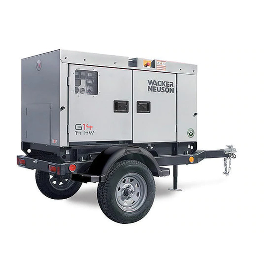
G 14 Machine Description and Intended Use This machine is a mobile electric power source. The Wacker Neuson Mobile Generator consists of a trailer-mounted cabinet containing an electric alternator, a fuel tank, and a diesel engine. A control panel, receptacles, and connection lugs are provided on the side of the cabinet. -
Page 9: Safety Guidelines For Operating The Machine
G 14 Safety Information Safety Guidelines for Operating the Machine DANGER Carbon monoxide. Using a generator indoors CAN KILL YOU IN MINUTES. Generator exhaust contains carbon monoxide (CO). This is a poison you cannot see or smell. If you can smell the generator exhaust, you are breathing CO. But even if you cannot smell the exhaust, you could be breathing CO. - Page 10 Safety Information G 14 Make a walk-around inspection of the generator set before starting it. Open side doors and visually inspect engine compartment for obvious damage or the presence of foreign objects which might affect operation. Follow starting and stopping instructions described in this manual. Know how to operate and stop the generator before starting it.
- Page 11 G 14 Safety Information Do not use the emergency stop button except in case of an actual emergency. Do not restart the engine until the cause of the trouble has been determined and fixed. Always do the following: Wear hearing protection when operating equipment.
-
Page 12: Operator Safety While Using Internal Combustion Engines
Safety Information G 14 Operator Safety while Using Internal Combustion Engines WARNING Internal combustion engines present special hazards during operation and fueling. Failure to follow the warnings and safety standards could result in severe injury or death. Read and follow the warning instructions in the engine owner’s manual and the safety guidelines below. -
Page 13: Towing Safety
G 14 Safety Information Towing Safety WARNING Towing a large trailer requires special care. To reduce the possibility of an accident: Both the trailer and vehicle must be in good condition. The trailer and the vehicle must be securely fastened to each other. -
Page 14: Table Of Contents G
Safety Information G 14 WARNING A poorly maintained machine can be a personal injury hazard. Follow the Periodic Maintenance schedule in this Operator’s Manual. Repair or replace any damaged or defective components immediately. Prerequisites Before servicing this machine: Stop the engine. -
Page 15: Label Locations
G 14 Labels Labels Label Locations wc_si000563gb.fm... - Page 16 Labels G 14 wc_si000563gb.fm...
-
Page 17: Label Meanings
G 14 Labels Label Meanings WARNING! Lock doors. Access can cause electric shock, arc flash, or injury. Read the Operator’s Manual for more information. WARNING! Pressurized contents. Do not open when hot! WARNING! Read and understand the supplied Operator’s Manual before operating the machine. - Page 18 Labels G 14 WARNING! To prevent hearing loss, wear hearing protection. Hand injury if entangled in moving belt. Rotating machinery! Do not reach inside with engine running. WARNING! Hot surface! NOTICE Avoid spraying water into generator. WARNING! Hot surface! WARNING! To prevent hearing loss, wear hearing protection when operating the machine.
- Page 19 G 14 Labels WARNING! To reduce the risk of electrical shock and arc flash, read the Operator’s Manual. Improper connection of the generator to a building’s electrical system can allow electrical current from the generator to backfeed into utility lines. This may result in electrocution of utility workers, fire, or explosion.
- Page 20 Labels G 14 Operator’s Manual must be stored on machine. Replacement Operator’s Manual can be ordered through your local Wacker Neuson distributor. Tie-down point. wc_si000563gb.fm...
- Page 21 G 14 Labels Electrical ground NOTICE Lifting point NOTICE Do not use as a lifting point. Operating the main circuit breaker supplies or interrupts power to the customer connection lugs. Neutral bonded to frame Low sulfur fuel or ultra low sulfur fuel only Engine wiring (DC schematic) wc_si000563gb.fm...
- Page 22 Labels G 14 Generator and receptacle wiring (AC schematic) A nameplate listing the model num- ber, item number, revision number, and serial number is attached to each unit. Please record the information found on this nameplate so it will be available should the nameplate become lost or damaged.
- Page 23 G 14 Labels Customer connection lugs Engine start switch Stop Glow plugs Crank – (On trailer) CAUTION Owner’s responsibility Tighten wheel nuts to 90–100 ft.lbs. Maintain rated tire pressure. Failure could result in accident or injury. wc_si000563gb.fm...
- Page 24 Labels G 14 – (On trailer) DANGER “Serious injury and/or property damage can result if this vehicle is towed before familiarizing yourself with the manufacturer’s operating instructions and cautions listed to the right.” CAUTION Before towing this trailer, check that:...
-
Page 25: Initial Setup And Overview
G 14 Initial Setup and Overview Initial Setup and Overview Application Generator This machine is a compact yet heavy-duty sound-attenuated generator designed to application provide single phase power for construction, commercial, and industrial applications where reliable power is needed. Safety notices Do not exceed the power output of the generator. -
Page 26: Included With The Machine
Initial Setup and Overview G 14 Included With the Machine Included with The following items are included with the machine: the machine (1) Operator’s Manual (1) Parts Book (1) engine operator’s manual (1) alternator and AVR (Automatic Voltage Regulator) manual... - Page 27 G 14 Initial Setup and Overview Notes: wc_tx001185gb.fm...
-
Page 28: Control Panel
Initial Setup and Overview G 14 Control Panel HOUR METER FUEL wc_gr006200 wc_tx001185gb.fm... - Page 29 G 14 Initial Setup and Overview Ref. Description Ref. Description Control panel access door Twist-lock receptacle (120/240 VAC, 30 Amp) Fuse access door GFI receptacle (120 VAC, 20 Amp) Main line circuit breaker Circuit breaker (120/240V, 50 Amp) Emergency stop...
-
Page 30: Battery
Initial Setup and Overview G 14 Battery Location and A battery is not supplied with the machine. See Technical Data for recommended description battery specifications. Install the battery behind the access panel at the rear of the machine and secure it with the retaining bracket. -
Page 31: Fueling The Machine
G 14 Initial Setup and Overview Precautions Observe the following precautions to prevent serious damage to the electrical system. Do not disconnect the battery while the machine is running. Do not attempt to run the machine without a battery. Do not attempt to jump-start a machine. -
Page 32: Generator Monitoring
Initial Setup and Overview G 14 Generator Monitoring Description Generator information is displayed on the four meters on the control panel. The meters display the operating voltage (h), frequency (j), and amperage (k). HOUR METER FUEL Generator Volts “V”—Displays the AC output voltage being produced by the generator. -
Page 33: Engine Monitoring
G 14 Initial Setup and Overview Engine Monitoring Description Engine operating information is displayed on two gauges (r, s) and on the indicator panel (f). HOUR METER FUEL wc_gr006277 Engine Engine Hours (r)—Displays the number of hours that the engine has been run. -
Page 34: Convenience Receptacles
Initial Setup and Overview G 14 Convenience Receptacles Description The generator is equipped with : one120V/240V twist-lock receptacle (l) rated at 50A one120V/240V twist-lock receptacle (m) rated at 30A three 120V duplex receptacles (n) with ground fault interrupts (GFI) Receptacles connect through the main line circuit breaker (c). In addition, each receptacle is protected by its own circuit breaker (o, p, q). -
Page 35: Emergency Stop Switch
G 14 Initial Setup and Overview Emergency Stop Switch Location The emergency stop switch is activated by pressing the red button located at the top of the right (control panel) side of the generator cabinet. The button can be accessed with the panel doors closed. It is electrically isolated from the switch and also from the metering panel. -
Page 36: Main Line Circuit Breaker
Initial Setup and Overview G 14 3.10 Main Line Circuit Breaker Location The main line circuit breaker (c) is located on the control panel. Operation In the off “O” position, the main line circuit breaker interrupts power from the alternator to the terminal lugs at the bottom of the generator panel. The main line circuit breaker also interrupts power to the convenience receptacle circuit breakers. -
Page 37: Thermal Overload Relay
G 14 Initial Setup and Overview 3.11 Thermal Overload Relay Description This machine is equipped with a thermal overload relay. If the machine is overloaded during normal operation, the relay will open and the main line circuit breaker will trip. -
Page 38: Voltage Output
Initial Setup and Overview G 14 3.13 Voltage Output Description The G 14 is capable of providing output voltages of 120V or 240V depending upon how the power cables are attached to the customer connection lugs. 240V 120V 120V wc_gr006202... -
Page 39: Before Starting
G 14 Initial Setup and Overview 3.15 Before Starting DANGER Carbon monoxide. Using a generator indoors CAN KILL YOU IN MINUTES. Generator exhaust contains carbon monoxide (CO). This is a poison you cannot see or smell. If you can smell the generator exhaust, you are breathing CO. But even if you cannot smell the exhaust, you could be breathing CO. -
Page 40: Transportation, Lifting, And Storage
Transportation, Lifting, and Storage G 14 Transportation, Lifting, and Storage Towing Provided The generator trailer is equipped with lights and a coupler connection. equipment wc_gr006305 Prerequisites Before towing the generator: Check that the towing vehicle and hitch have a rating equal to or greater than the GVWR. -
Page 41: Lifting
G 14 Transportation, Lifting, and Storage Lifting Prerequisites Before lifting the generator: refer to Technical Data for the proper operating weight of the generator make sure the lifting devices have sufficient capacity to lift the machine safely make sure the winch or crane to be used for lifting the machine is in operable... -
Page 42: Operation
Operation G 14 Operation Breaking In New Machines Run the generator at least 60–100% of continuous load for the first 100 hours. Change engine oil and replace oil filter after the first 50 hours. Starting the Generator Prerequisites Wires at the customer connection lugs are connected for the proper voltage output. -
Page 43: Operating The Generator
G 14 Operation Operating the Generator Switch Leave the engine start switch (g) in the ON (first) position while the generator is position operating. STOP HOUR METER FUEL wc_gr006213 Allow the generator to operate for a few minutes to warm the engine before closing the main circuit breaker. -
Page 44: Engine Shutdown Faults
Operation G 14 Engine Shutdown Faults Description The engine control unit (ECU) continuously monitors vital engine functions for fault conditions. When a fault occurs, the engine stops automatically and indicators on the panel flash to identify the specific fault condition. See the chart below. - Page 45 G 14 Operation Indicator Indicator panel display Possible causes Load center cover open. Load center cover open Faulty lug door interlock switch. Faulty lug door interlock switch wiring. Note: If the load center cover is opened while the generator is operating, the main line cir- cuit breaker will trip.
-
Page 46: Stopping The Generator
Operation G 14 Stopping the Generator Before Check with other personnel on the jobsite and let them know that power is being stopping turned off. Make sure that the power shutdown will not create any hazards by turning off devices such as pumps, heaters, or lights that may need to be kept on. -
Page 47: Maintenance
G 14 Maintenance Maintenance Periodic Maintenance Schedule The table below lists basic machine and engine maintenance. Tasks designated with check marks may be performed by the operator. Tasks designated with square bullet points require special training and equipment. Refer to the engine owner’s manual for additional information. -
Page 48: Checking Fuses
Maintenance G 14 Every Every Every Every Every Every First Every Every Daily 1000 1500 3000 50 hr 1 yr 2 yr Change engine oil. Check fan belt tightness. Replace oil filter cartridge. Check fuel pipes and clamps. Replace intake air hose. -
Page 49: Maintaining The Air Cleaner
G 14 Maintenance Maintaining the Air Cleaner Prerequisite Machine is stopped When Evacuator valve (f): Open once a week under ordinary operating conditions. When the machine is operated in extremely dusty conditions, open the evacuator valve daily. Air cleaner elements (b,c): Clean every 250 hours. -
Page 50: Checking The Engine Oil
Maintenance G 14 Checking the Engine Oil Prerequisites Engine is stopped Machine is on a level surface Fresh oil is available (see Technical Data for type and quantity) When Check engine oil daily before starting the engine, or more than 5 minutes after stopping the engine. -
Page 51: Changing The Engine Oil And Filter
G 14 Maintenance Changing the Engine Oil and Filter Prerequisites Engine is stopped, but still warm Machine is on a level surface Fresh engine oil and new filter are available (see engine operator’s manual) Plastic cloth and a container of sufficient volume to collect drained oil are... - Page 52 Maintenance G 14 Continued from the previous page. 3. Screw in the cartridge by hand. When the gasket contacts the seal surface, tighten the cartridge firmly by hand. NOTICE: Do not use a filter wrench to tighten the cartridge. Doing so can over- tighten the cartridge and damage the seal surface.
-
Page 53: Checking The Engine Coolant Level
G 14 Maintenance Checking the Engine Coolant Level Prerequisites Machine shut down Engine cool When Daily Procedure Follow the procedure below to check the engine coolant level. WARNING Burn hazard. Engine coolant is hot and under pressure at operating temperature. It can cause severe personal injury. -
Page 54: Replacing The Coolant
Maintenance G 14 Replacing the Coolant Prerequisites Engine stopped Engine cool Plastic cloth and a container of sufficient volume to collect drained coolant Fresh coolant: long-life ethylene glycol type, 6.9 L (7.3 qt) Note: Collect, store and dispose of drained coolant in accordance with current environ- mental protection regulations. -
Page 55: Replacing The Fuel Filter Element
G 14 Maintenance Replacing the Fuel Filter Element Location The fuel filter is located behind the access door on the left (panel) side of the machine. Prerequisites Engine is stopped Replacement fuel filter element is on hand When Replace the fuel filter element every 500 hours of operation. -
Page 56: Bleeding Air From The Fuel System
Maintenance G 14 Bleeding Air From the Fuel System Prerequisites Engine is stopped Engine is cool to the touch When Air bleeding of the fuel system is required if: the fuel filter and pipes have been detached and re-installed the fuel tank has been emptied or run dry... -
Page 57: Cleaning The Water Separator
G 14 Maintenance 6.10 Cleaning the Water Separator Location The water separator is located behind the access door on the control side of the machine. Prerequisites Engine is stopped Clean diesel fuel and clean, dry rags on hand When Clean the water separator every 250 hours of operation. An indicator mark on the separator provides visual notification that the water separator must be cleaned. -
Page 58: Maintaining The Trailer
Maintenance G 14 6.11 Maintaining the Trailer Tires Keep tires inflated to the proper pressure as shown on the tire sidewall. Check tread periodically for wear. Replace tires as required. Wheels Check that lug nuts holding wheels are tight. Replace any missing lug nuts immediately. -
Page 59: Troubleshooting
G 14 Maintenance 6.12 Troubleshooting Problem Cause Remedy Engine is difficult to start 1. Fuel is contaminated 1. Clean fuel filter and fuel tank. Remove 2. Valve clearance is water, dirt, and other incorrect impurities. 3. Engine oil is thick due 2. - Page 60 Maintenance G 14 Problem Cause Remedy Engine revolution sud- Fuel system problem Consult engine opera- denly decreases or tor’s manual. increases Engine overheats Coolant problem Consult engine opera- tor’s manual Oil pressure indicator illu- 1. Low engine oil 1. Add engine oil.
-
Page 61: Technical Data
G 14 Technical Data Technical Data Engine Engine Power Rating Engine power rating per ISO/TR 14396. Actual power output may vary due to conditions of specific use. Model G 14 Engine Engine make Kubota Engine model D1703-M-E3BG Interim Tier 4... -
Page 62: Generator Data
Technical Data G 14 Generator Data Machine G 14 Generator Make/Type Stamford Model PI044G Generator speed AC voltages available 1Ø (V) 120, 240 Frequency 60 Hz Power factor 1Ø Voltage regulation ±1.00% Insulation class Sound level at 7 m (23 ft.) -
Page 63: Trailer And Skid Data
G 14 Technical Data Trailer and Skid Data Item No. G 14 Generator Dry weight kg (lb) 651 (1432.2) Operating weight kg (lb) 727 (1599.4) Trailer weight kg (lb) 158 (348) without generator GVWR kg (lb) 1134 (2500) Tires size... -
Page 64: Schematics
Schematics G 14 Schematics DC Schematic wc_tx001170gb.fm... - Page 65 G 14 Schematics Wire Colors Black Brown Green Yellow Gray Blue Violet Orange PINK Pink White Light blue Notes: wc_tx001170gb.fm...
-
Page 66: Ac Schematic
Schematics G 14 AC Schematic wc_tx001170gb.fm... -
Page 67: Blk Grn Blu Pink
G 14 Schematics Wire Colors Black Brown Green Yellow Gray Blue Violet Orange PINK Pink White Light blue Notes: wc_tx001170gb.fm... - Page 68 Tel. : (262) 255-0500 Fax: (262) 255-0550 Tel.: (800) 770-0957 Wacker Neuson Limited - Room 1701–03 & 1717–20, 17/F. Tower 1, Grand Century Place, 193 Prince Edward Road West, Mongkok, Kowloon, Hongkong. Tel: (852) 3605 5360, Fax: (852) 2758 0032...
Need help?
Do you have a question about the G 14 and is the answer not in the manual?
Questions and answers