
Subscribe to Our Youtube Channel
Related Manuals for Wacker Neuson G 100


Summary of Contents for Wacker Neuson G 100
- Page 1 Operator’s Manual Mobile Generator G 100 G 120 5000185616 0911...
- Page 2 Copyright notice © Copyright 2011 by Wacker Neuson Production Americas LLC All rights, including copying and distribution rights, are reserved. This publication may be photocopied by the original purchaser of the machine. Any other type of reproduction is prohibited without express written permission from Wacker Neuson Production Americas LLC.
- Page 3 Refer to the separate Repair Manual for detailed instructions on servicing and repairing the machine. If you are missing any of these documents, please contact Wacker Neuson to order a replacement or visit www.wackerneuson.com. When ordering parts or requesting service information, be prepared to provide the machine model number, item number, revision number, and serial number.
- Page 4 Serious injury hazards to the operator and persons in the work area Permanent damage to the machine which will not be covered under warranty Contact your Wacker Neuson dealer immediately if you have questions about approved or unapproved parts, attachments, or modifications.
- Page 5 G 100 / G 120 Foreword wc_tx000994gb.fm...
- Page 6 Foreword G 100 / G 120 wc_tx000994gb.fm...
-
Page 7: Table Of Contents
G 100 / G 120 Table of Contents Foreword Safety Information Signal Words Used in this Manual ............. 11 Machine Description and Intended Use ..........11 Safety Guidelines for Operating the Machine ........13 Operator Safety while Using Internal Combustion Engines ....15 Towing Safety .................. - Page 8 Table of Contents G 100 / G 120 4.14 Manual Start-Up .................. 48 4.15 Operation .................... 50 4.16 Engine Monitoring ................52 4.17 Engine Power Correction Factors ............53 4.18 Engine Shutdown Faults ..............54 4.19 Current Overload Fault ............... 55 4.20...
- Page 9 G 100 / G 120 Table of Contents Maintenance Periodic Maintenance Schedule ............77 Breaking In New Machines ..............78 Resetting the Periodic Maintenance Timer ........78 Replacing the Air Filter Element ............79 Replacing the Racor® Filter Element (if equipped) ......80 Lubricating the Engine ................
- Page 10 Table of Contents G 100 / G 120 wc_bo5000185616_04TOC.fm...
-
Page 11: Safety Information
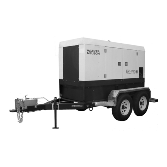
Note: A Note contains additional information important to a procedure. Machine Description and Intended Use This machine is a mobile electric power source. The Wacker Neuson Mobile Generator consists of a trailer-mounted cabinet containing an electric alternator, a fuel tank, and a diesel engine. A control panel, receptacles, and connection lugs are provided on the side of the cabinet. - Page 12 Safety Information G 100 / G 120 This machine is intended for the purpose of supplying electrical power to connected loads. Refer to the product specifications for the output voltage and frequency of this generator, and for the maximum output power limit of this generator.
-
Page 13: Safety Guidelines For Operating The Machine
G 100 / G 120 Safety Information Safety Guidelines for Operating the Machine Familiarity and proper training are required for the safe operation of the machine. Machines operated improperly or by untrained personnel can be dangerous. Read the operating instructions... - Page 14 Safety Information G 100 / G 120 1.3.10 Do not start a machine in need of repair. 1.3.11 Use the emergency stop button only in an actual emergency. Do not restart the engine until the cause of the trouble has been determined and fixed.
-
Page 15: Operator Safety While Using Internal Combustion Engines
G 100 / G 120 Safety Information Operator Safety while Using Internal Combustion Engines WARNING Internal combustion engines present special hazards during operation and fueling. Failure to follow the warnings and safety standards could result in severe injury or death. -
Page 16: Towing Safety
Safety Information G 100 / G 120 Towing Safety WARNING Towing a large trailer requires special care. To reduce the possibility of an accident: Both the trailer and vehicle must be in good condition. The trailer and the vehicle must be securely fastened to each other. -
Page 17: Service Safety
G 100 / G 120 Safety Information Service Safety A poorly maintained machine can become a safety hazard! In order for the machine to operate safely and properly over a long period of time, periodic maintenance and occasional repairs are necessary. - Page 18 Safety Information G 100 / G 120 1.6.7 Do not modify the machine without the express written approval of the manufacturer. 1.6.8 Do not pressure wash the control panel, generator end, or any other electrical components when cleaning the unit. Never allow water to accumulate around the base of the generator set.
-
Page 19: Labels
G 100 / G 120 Labels Labels Label Locations A, Z Ø DIAGNOSTICS DIAGNOSEN DIAGNOSTICOS DIAGNOSTICS M, N DANGER STOP GEFAHR DIESEL PELIGRO DANGER WARNING Lock doors. Access can cause electric shock or injury. Arc flash hazard! WARNUNG Turen schliessen! Zugang kann elektrischen Schlag oder Verletzung verursachen. - Page 20 Labels G 100 / G 120 WARNING WARNING Lock doors. Access can cause electric shock or injury. Lock doors. Access can cause electric shock or injury. Arc flash hazard! Arc flash hazard! WARNUNG WARNUNG Turen schliessen! Zugang kann elektrischen Schlag oder Turen schliessen! Zugang kann elektrischen Schlag oder Verletzung verursachen.
-
Page 21: Label Meanings
G 100 / G 120 Labels Label Meanings WARNING! Lock doors. Access can cause electric shock, arc flash, or injury. Read the Operator’s Manual for more information. WARNING! Pressurized contents. Do not open when hot! WARNING! Read and understand the supplied Operator’s Manual before operating the... - Page 22 Labels G 100 / G 120 DANGER! Asphyxiation hazard. Do not run the machine indoors or in an enclosed area without adequate ventilation. Read the Operator’s Manual for instructions. No sparks, flames, or burning objects near machine. Stop the engine before adding fuel. Use only diesel fuel.
- Page 23 G 100 / G 120 Labels WARNING! Disconnect battery before servicing. Read the Operator’s Manual. WARNING! Generator can automatically start which can cause serious injury. Disconnect battery before servicing. WARNING! To reduce the risk of electrical shock and arc flash, read the Operator’s Manual. Improper connection of the generator to a building’s...
- Page 24 Labels G 100 / G 120 Operator’s Manual must be stored on machine. Replacement Operator’s Manual can be ordered through your local Wacker Neuson distributor. Remote start operation. Read Operator’s Manual for instructions. wc_si000546gb.fm...
- Page 25 G 100 / G 120 Labels Tie-down point Electrical ground NOTICE Lifting point. Operating the main circuit breaker supplies or interrupts power to the customer connection lugs. Neutral bonded to frame Engine wiring INTAKE HEATER 10AWG NOT USED ON SOME MODELS...
- Page 26 Labels G 100 / G 120 Generator and Receptacle Wiring WARNING Electric shock at cooling fins. A nameplate listing the model number, item number, revision number, and serial number is attached to each unit. Please record the information found on this nameplate so it will be available should the nameplate become lost or damaged.
- Page 27 G 100 / G 120 Labels Fuel drain Hand hold WARNING! To prevent hearing loss, wear hearing protection when operating the machine. WARNING! Hand injury if entangled in moving belt. WARNING WARNING! WARNUNG ADVERTENCIA Rotating machinery! Do not reach inside AVERTISSEMENT machine with engine running.
- Page 28 Labels G 100 / G 120 (if equipped) Battery disconnect must be in “ON” position to start engine. NOTICE: Do not use the battery disconnect switch while engine is running. Damage to the electrical components may occur. Fuses (if equipped)
- Page 29 G 100 / G 120 Labels Diagnostic menu navigation Remote start operation. Read Operator’s Manual for instructions. DANGER Start only from seat in park or neutral. Starting in gear kills. (This label appears on the John Deere engine but does not apply to this machine.) Lug door must be closed for lugs and receptacles to energize.
- Page 30 Labels G 100 / G 120 (Camlock models only) WARNING! Electric shock and arc flash can cause serious injury or death. wc_si000546gb.fm...
-
Page 31: Lifting And Transporting
G 100 / G 120 Lifting and Transporting Lifting and Transporting Lifting the Machine Prerequisites Before lifting the generator: • refer to the Technical Data section for the proper operating weight of the generator • make sure the lifting devices have sufficient capacity to lift the machine safely •... - Page 32 Lifting and Transporting G 100 / G 120 • Make sure that the hitch and coupler are compatible. The generator trailer is equipped with a pintle type coupler (a). • Check that the directional and running lights on the trailer are working.
- Page 33 G 100 / G 120 Lifting and Transporting Notes: wc_tx001191gb.fm...
-
Page 34: Operation
1. Make sure all loose packaging materials have been removed from the machine. 2. Check the machine and its components for damage. If there is visible damage, do not operate the machine! Contact your Wacker Neuson dealer immediately for assistance. -
Page 35: Refueling The Machine
G 100 / G 120 Operation Refueling the Machine Requirements Machine shut down Engine cool Machine/fuel tank level with the ground Fresh, clean fuel supply Procedure Perform the procedure below to refuel the machine. WARNING Fire hazard. Fuel and its vapors are extremely flammable. Burning fuel can cause severe burns. -
Page 36: Control Panel
Operation G 100 / G 120 Control Panel DIAGNOSTICS DIAGNOSTICS DIAGNOSEN DIAGNOSEN DIAGNOSTICOS DIAGNOSTICOS DIAGNOSTICS DIAGNOSTICS Ø DIAGNOSTICS DIAGNOSEN DIAGNOSTICOS DIAGNOSTICS wc_gr006136 wc_tx001687gb.fm... - Page 37 G 100 / G 120 Operation Ref. Description Ref. Description Main circuit breaker Interlock switch Voltage adjustment rheostat Customer connection terminal lugs Hour meter Ground connection Pre-alarm/shutdown LED Bond bar LCD panel Customer connection terminal lugs door Engine start switch...
-
Page 38: Main Line Circuit Breaker
Operation G 100 / G 120 Main Line Circuit Breaker Location The main line circuit breaker is located on the control panel. Operation In the “off” position, the main line circuit breaker interrupts power from the selector switch to the terminal lugs at the bottom of the generator panel. -
Page 39: Engine Start Switch
G 100 / G 120 Operation Engine Start Switch Location and The engine start switch (f) is located on the right side of the control panel. It is a description three-position switch: “REMOTE START,” off “O,” and “START/RUN.” Ø APAGADO... -
Page 40: Warning Light
Operation G 100 / G 120 Warning Light Location and The amber warning light (d) is located on the metering panel. The light serves as a description pre-alarm and turns on prior to a potential engine fault condition. At the same time that the light goes on, the LCD panel will begin blinking to indicate which engine function is approaching its fault value. -
Page 41: Voltage Selector Switch
G 100 / G 120 Operation Voltage Selector Switch Location The voltage selector switch is located inside the generator enclosure near the engine air cleaner. To access the switch, open the rear door on the left side of the generator enclosure. -
Page 42: Voltage Selector Label
Operation G 100 / G 120 Voltage Selector Label Location The voltage selector label is found on the inside of the hinged terminal access door to the customer connection lugs. wc_gr005696 WARNING Hazardous voltage! Improperly connected terminals can cause severe electrical shock, burns, or death. -
Page 43: Adjusting Voltage With The Rheostat
G 100 / G 120 Operation Adjusting Voltage with the Rheostat Location and The voltage adjustment rheostat (b) is located directly to the right of the metering description panel. Use the rheostat to adjust the AC voltage output. Ø APAGADO... -
Page 44: Connection Lugs
Operation G 100 / G 120 4.10 Connection Lugs Location and The customer connection lugs are located on the lower right side of the control box description behind a hinged terminal door. The lugs provide connection points for attachment of outside loads. -
Page 45: Grounding The Generator
G 100 / G 120 Operation 4.11 Grounding the Generator Location A ground connection is located at the customer connection terminal lugs. wc_gr008288 Function This ground connection is used for electrically grounding the generator when necessary to comply with the National Electrical Code and other federal, state, and local regulations. -
Page 46: Convenience Receptacles
Operation G 100 / G 120 4.12 Convenience Receptacles Description The generator is equipped with : three 120V/240V twist-lock receptacles (m) rated at 50A two 120V duplex receptacles (n) with ground fault interrupts (GFI) Receptacles do not connect through the main line circuit breaker. Each receptacle is protected by its own circuit breaker (h,k). -
Page 47: Before Starting
G 100 / G 120 Operation 4.13 Before Starting Explanation Before putting the generator into service, review each item on the following checklist. Because generators often run unattended for long periods of time, it is important to make sure that the machine is set up properly to reduce the possibility of malfunction. -
Page 48: Manual Start-Up
Operation G 100 / G 120 4.14 Manual Start-Up Explanation Before starting the generator set for the first time, thoroughly review the “Before starting” checklist in the previous section. Proceed with generator starting only after checking each item in that section. - Page 49 G 100 / G 120 Operation 10. See Basic Troubleshooting to identify possible causes and remedies for the starting problem. Correct the problem before attempting to start the engine again. 11. To repeat crank cycle, return start switch to off “O” to reset engine control module.
-
Page 50: Operation
Operation G 100 / G 120 4.15 Operation Switch Leave the engine start switch (f) in the START/RUN position while the generator is positions operating. If the generator was started using a remote switch, leave the engine start switch in the REMOTE START position. - Page 51 G 100 / G 120 Operation Hertz “Hz” - Displays output frequency. This gauge should read approximately 60 Hz under a no-load condition. If the frequency is too high, check the engine rpm. Sample display with engine running. Ø 208 P1 24 61.5 85% 175 78 14.3...
-
Page 52: Engine Monitoring
Operation G 100 / G 120 4.16 Engine Monitoring Description With the engine start switch set to “RUN/START” or “REMOTE START”, engine information will be continuously displayed on the bottom line of the LCD panel. Indicators Symbol Meaning Description Displays engine oil pressure between 0–100 psi. -
Page 53: Engine Power Correction Factors
G 100 / G 120 Operation 4.17 Engine Power Correction Factors Performance Performance data on John Deere engines are measured at the following standard data conditions: conditions 744 mm (29.31 in.) of mercury dry air pressure 183 m (600 ft.) altitude 0% relative humidity 25°C (77°F) air intake temperature... -
Page 54: Engine Shutdown Faults
Operation G 100 / G 120 4.18 Engine Shutdown Faults Description The engine control module (ECM) continuously monitors vital engine functions for fault conditions. When a fault condition occurs, the engine will shut down and the LCD panel will display the fault causing the shutdown. -
Page 55: Current Overload Fault
G 100 / G 120 Operation 4.19 Current Overload Fault Along with engine functions, the ECM continuously monitors the current load in each phase. The values for current overload are programmed into the ECM at the factory and are different for each generator size. -
Page 56: Stopping
Operation G 100 / G 120 4.21 Stopping Check with other personnel on the jobsite and let them know that power is being turned off. Make sure that the power shutdown will not create any hazards by turning off devices such as pumps, heaters, or lights that may need to be kept on. -
Page 57: Racor® Crankcase Filter (If Equipped)
G 100 / G 120 Operation 4.22 Racor® Crankcase Filter (if equipped) Location The Racor crankcase filter (a) is located next to the engine. Description The crankcase filter removes oil from engine blow-by. Coalesced oil drains into the engine oil pan. Filtered air is then routed to the engine intake system. -
Page 58: Cold Weather Start-Up
Operation G 100 / G 120 4.23 Cold Weather Start-Up Prerequisites Before starting the generator in cold weather make sure that: the battery is at peak power the correct weight motor oil is being used the starter motor is in good condition... -
Page 59: Automatic/Remote Start-Up
G 100 / G 120 Operation 4.25 Automatic/Remote Start-Up Background In the REMOTE START position, the generator can be started remotely, either through a transfer switch or some other type of remote start switch. REMOTE START is the normal setting when using the generator as a stand-by power supply. -
Page 60: Remote/Transfer Switch
Operation G 100 / G 120 4.26 Remote/Transfer Switch Background A transfer switch is designed to transfer electrical loads from the normal power source (utility) to the emergency power source (generator) when normal voltage falls below a prescribed level. The transfer switch automatically returns the load back to the normal source when power is restored back to operating levels. -
Page 61: Using The Lcd Panel And Keypad
Mobile Generator Using the LCD Panel and Keypad Using the LCD Panel and Keypad See graphic: wc_gr005938, wc_gr006064 During normal operation, the LCD panel (e) displays current information on machine performance and operating status. The keypad (g) provides access to additional monitoring functions through a series of menus displayed on the LCD panel. -
Page 62: Navigating The Menus
Using the LCD Panel and Keypad Mobile Generator Navigating the Menus The label pictured below is a navigational aid to access the various diagnostic menus programmed into the LCD. See the accompanying table for information about the menu items. Metering Engine DIAGNOSTIC MENU Metering... - Page 63 Mobile Generator Using the LCD Panel and Keypad Menu Item Description Menu Item Description Alarm Config Alarm configuration J1939 Active DTC Diagnostic Trouble Codes Alarm Configuration J1939 Data Alarms J1939 Engine Config Engine configuration Alarm–Status J1939 Previous DTC Diagnostic Trouble Codes Amps Kilovolt-amps...
-
Page 64: Entering Passwords
Note: The default password is OP and is set by the factory. Contact your Wacker Neuson dealer if you need to have the password reset. Follow the steps below to enter a password. -
Page 65: Adjusting Screen Contrast
Mobile Generator Using the LCD Panel and Keypad Adjusting Screen Contrast The display contrast of the LCD panel can be adjusted to suit the operator’s preference, or for increased visibility in jobsites with low or bright ambient light. 5.3.1 To access the main menu, press the right arrow button (1) on the keypad (g). -
Page 66: Setting The Time Or Date
Using the LCD Panel and Keypad Mobile Generator Setting the Time or Date See graphic: wc_gr005938 The control module features a clock powered by a separate battery. Follow the steps below to change the time or date. 5.4.1 To access the main menu, press the right arrow button (1) on the keypad (g). -
Page 67: Changing User Preferences
Mobile Generator Using the LCD Panel and Keypad Changing User Preferences Changing Display Units The LCD panel can be configured by the operator to display system information in either metric units or English units. 5.5.1 To access the main menu, press the right arrow button (1) on the keypad (g). -
Page 68: Changing / Disabling Low Fuel Fault
Using the LCD Panel and Keypad Mobile Generator Changing / Disabling Low Fuel Fault See graphic: wc_gr005938 The low fuel fault value can be changed or disabled through the diagnostics menu. (For example, you may wish to reduce the value so that the machine operates for a longer period before running out of fuel.) Note: The engine will shut down if the machine runs out of fuel. -
Page 69: Changing Cooldown Time
Mobile Generator Using the LCD Panel and Keypad Changing Cooldown Time See graphic: wc_gr005938 A cooldown timer activates when the machine is no longer receiving a remote run signal. This timer is factory set to zero (0) minutes. The cooldown time can be changed if desired. 5.7.1 To access the main menu, press the right arrow button (1) on the keypad (g). -
Page 70: Factory-Installed Options
This machine may be equipped with one or more of the following factory-installed options. To verify if any of these options are installed on your machine, contact the Wacker Neuson Corporation at 1-800-770-0957. A nameplate listing the Model Number, Item Number, Revision, and Serial Number is attached to each unit. -
Page 71: Automatic Lcd Heat
G 100 / G 120 Factory-Installed Options Automatic LCD Heat To improve the performance of the LCD panel in cold weather, the LCD panel control module is equipped with an LCD heater. The heater draws power from the panel control module and is active only when the panel control module is powered. -
Page 72: Low Coolant Shutdown
Factory-Installed Options G 100 / G 120 Low Coolant Shutdown The low-coolant shutdown system consists of an electronic sensor that monitors coolant level. The sensor (a) is mounted to the radiator and wired into the ECM. The sensor probe (b) is submerged in radiator coolant. -
Page 73: Lube Level Maintainer
G 100 / G 120 Factory-Installed Options Lube Level Maintainer The lube level maintainer system protects the engine from low oil levels by providing an additional 6-quart oil reservoir. Oil from the reservoir is gravity-fed from the oil reservoir (a) through the control valve (b) and into the engine oil pan as needed. -
Page 74: Temperature-Activated Shutters
Factory-Installed Options G 100 / G 120 Temperature-Activated Shutters The shutters (a) are mounted to the top of the generator enclosure. The shutters are designed to keep the engine compartment warm, thus increasing engine temperature during cold weather operation. The shutters are activated through a wax-pellet actuator (b) that is connected to the generator's cooling system. -
Page 75: Camlocks
G 100 / G 120 Factory-Installed Options Camlocks A second optional outlet panel features camlock connectors for easy tool changes. Each connector is protected by a spring-loaded cover. NOTICE: Separate overcurrent protection must be provided. Do not exceed 400 amps per receptacle. -
Page 76: Quick-Disconnect Fuel Fittings
Factory-Installed Options G 100 / G 120 Quick-Disconnect Fuel Fittings Quick-disconnect fuel fittings allow an external fuel supply to be connected to the engine. Requirements Engine stopped and cool to the touch Fuel supply and return hoses with compatible quick-disconnect fittings Note: Required fitting size is ISO 7241-1-Series B (3/8 in.) -
Page 77: Maintenance
G 100 / G 120 Maintenance Maintenance Periodic Maintenance Schedule The table below lists basic machine maintenance. Tasks designated with check marks may be performed by the operator. Tasks designated with square bullet points require special training and equipment. Every... -
Page 78: Breaking In New Machines
Maintenance G 100 / G 120 Breaking In New Machines Run the generator at least 60–100% of continuous load for the first 100 hours. Change engine oil and replace oil filter after the first 100 hours. Resetting the Periodic Maintenance Timer After maintenance has been performed on the generator, it is necessary to reset the periodic maintenance timer. -
Page 79: Replacing The Air Filter Element
G 100 / G 120 Maintenance 6. If necessary, enter your password. (See Entering Passwords for more information.) 7. When prompted, select YES and press the check mark button. 8. Exit by repeatedly pressing the left arrow button (4) until the LCD panel display returns to monitoring status. -
Page 80: Replacing The Racor® Filter Element (If Equipped)
Maintenance G 100 / G 120 Replacing the Racor® Filter Element (if equipped) When Replace the filter element after every 750 hours of operation, or whenever the red filter service indicator appears. Prerequisites Engine is stopped Replacement filter element and O-rings are available... -
Page 81: Lubricating The Engine
G 100 / G 120 Maintenance Lubricating the Engine Checking oil Check engine oil daily before starting engine. WARNING Burn hazard. Engine, engine oil, muffler, and exhaust pipes become extremely hot during operation. Stop the engine and allow the machine to cool before checking the oil or replac- ing the engine oil or oil filter cartridge. -
Page 82: Checking The Engine Coolant Level
Maintenance G 100 / G 120 Checking the Engine Coolant Level Prerequisites Machine shut down Engine cool When Daily Procedure Follow the procedure below to check the engine coolant level. WARNING Burn hazard. Engine coolant is hot and under pressure at operating temperature. It can cause severe personal injury. -
Page 83: Maintaining The Trailer
G 100 / G 120 Maintenance Maintaining the Trailer Tires Keep tires inflated to the proper pressure as shown on the tire sidewall. Check tread periodically for wear. Replace tires as required. Wheels Check that lug nuts holding wheels are tight. -
Page 84: Storage
Maintenance G 100 / G 120 Storage Introduction Extended storage of equipment requires preventative maintenance. Performing these steps helps to preserve machine components and ensures the machine will be ready for future use. While not all of these steps necessarily apply to this machine, the basic procedures remain the same. -
Page 85: Basic Troubleshooting
Mobile Generators Basic Troubleshooting Basic Troubleshooting Problem Cause Remedy Engine doesn’t start Battery discharged Charge battery. Battery connections cor- Clean battery connections. roded Blown fuse Replace fuse. Defective starter Replace starter. Engine tries to start but No fuel Fill tank with fuel. stops Bleed fuel lines. -
Page 86: Technical Data
Technical Data G 100 / G 120 Technical Data Engine Engine Power Rating Engine power rating per ISO/TR 14396. Actual power output may vary due to conditions of specific use. Item No. G 100 G 120 Engine Engine make John Deere 4.5L... -
Page 87: Generator
G 100 / G 120 Technical Data Generator Item No. G 100 G 120 Generator Make/Type Mecc Alte Model ECP34-2S/4 ECP34-1L/4 Generator speed Voltage selector 3 position switch 3Ø hi-wye, 3Ø lo-wye, 1Ø zig-zag 277/480, 120/208, 120/240 AC voltages available 1Ø... -
Page 88: Trailer And Skid
Technical Data G 100 / G 120 Trailer and Skid Item No. G 100 G 120 Generator Dry weight (no trailer) kg (lbs.) 2131 (4699) 2143 (4725) Operating weight (no trailer) kg (lbs.) 2783 (6137) 2795 (6163) Trailer weight kg (lbs.) -
Page 89: Dimensions
G 100 / G 120 Technical Data Dimensions G 100 G 120 2784 (110.0) (in.) 1143 (45.0) 1727 (68.0) wc_gr005086 wc_td000298gb.fm... - Page 90 Technical Data G 100 / G 120 Notes: wc_td000298gb.fm...
-
Page 91: Schematics
G 100 / G 120 Schematics 10 Schematics This page is intentionally left blank. wc_tx000998gb.fm... -
Page 92: Engine Wiring
Schematics G 100 / G 120 10.1 Engine Wiring 12 12 10AWG 10AWG 59 59 GROUND 1 GROUND 1 12 12 BAT - BAT - 80 80 BAT+ BAT+ 53 53 65 65 13 13 RELAY RELAY 62 62 FUEL LEVEL 9... -
Page 93: Engine Wiring Components
G 100 / G 120 Schematics 10.2 Engine Wiring Components Ref. Description Ref. Description Electronic control board Toggle switch Engine outputs 10A fuse Engine sensor inputs Main breaker Emergency stop, canbus, and Lug door safety switch contact outputs Fuses Mechanical lugs... -
Page 94: Electrical Schematic
Schematics G 100 / G 120 10.3 Electrical Schematic... -
Page 95: Electrical Schematic Components
G 100 / G 120 Schematics 10.4 Electrical Schematic Components Ref. Description Ref. Description Lug safety limit switch Generator Mechanical lugs Voltage regulator Plug 5 - current transformer Voltage adjustment rheostat Plug 4 - line voltage inputs Terminal block Shunt... - Page 98 Tel. : (262) 255-0500 Fax: (262) 255-0550 Tel.: (800) 770-0957 Wacker Neuson Limited - Room 1701–03 & 1717–20, 17/F. Tower 1, Grand Century Place, 193 Prince Edward Road West, Mongkok, Kowloon, Hongkong. Tel: (852) 3605 5360, Fax: (852) 2758 0032...
Need help?
Do you have a question about the G 100 and is the answer not in the manual?
Questions and answers