
Subscribe to Our Youtube Channel
Related Manuals for PPI Clavex Pro


Summary of Contents for PPI Clavex Pro
- Page 1 Clavex Pro Clavex Pro User Manual Enhanced Autoclave Sterilization Controller User Manual...
-
Page 2: Table Of Contents
Clavex Pro User Manual CONTENTS 1. FRONT PANEL LAYOUT 2. BASIC OPERATION 3. SET UP MODE : ACCESS & OPERATION 4. PAGE 10 : INPUT / OUTPUT CONFIGURATION PARAMETERS 5. PAGE 15 : SOAK TIMER PARAMETERS & OPERATION DETAILS 6. PAGE 11 : SUPERVISORY PARAMETERS 7. -
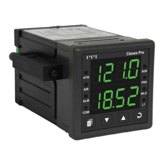
Page 3: Front Panel Layout
Clavex Pro User Manual Section 1 FRONT PANEL LAYOUT The controller front panel comprises of digital readouts, LED indicators and tactile keys as shown in Figure 1.1 below. Figure 1.1 Clavex Pro Upper Readout Lower Readout - Soak Timer Heater Status Indicator... - Page 4 Clavex Pro User Manual KEYS The Table 1.2 lists the four front panel keys and the associated function. Table 1.2 Symbol Function Press to enter or exit set-up mode. PAGE Press to decrease the parameter value. Pressing once decreases the value by one count; keeping pressed speeds up DOWN the change.
-
Page 5: Basic Operation
Clavex Pro User Manual Section 2 BASIC OPERATIONS POWER-UP Upon power-up all displays and indicators are lit on for approximately 3 seconds. This is followed by the indication of the controller model name (CLAv) on the Upper Readout and the firmware version (01.05) on the Lower Readout, for approximately 1 second. - Page 6 Clavex Pro User Manual Notes 1) The running cycle is aborted if Low water level is detected. Also, a new start command is not accepted until the water level error is removed. While the level is low, the Lower Readout flashes the message (Low Level).
- Page 7 Clavex Pro User Manual Press ENTER key. The Lower Readout shows prompt for the first available operator parameter and the Upper Readout shows value for the parameter. Use UP/DOWN keys to adjust the value and then press ENTER key to store the set value and scroll to the next parameter.
-
Page 8: Set Up Mode : Access & Operation
Clavex Pro User Manual Section 3 SET-UP MODE : ACCESS AND OPERATION The various parameters are arranged in different groups, called PAGES, depending upon the functions they represent. Each group is assigned a unique numeric value, called PAGE NUMBER, for its access. - Page 9 Clavex Pro User Manual MASTER LOCKING The controller facilitates locking all the PAGES (except Operator PAGE) by applying Master Lock Code. Under Locking, the parameters are available for view only and cannot be adjusted. The Master Lock, however does not lock the operator parameters .
-
Page 10: Input / Output Configuration Parameters
Clavex Pro User Manual Section 4 PAGE 10 : INPUT / OUTPUT CONFIGURATION PARAMETERS Table 4.1 Settings Parameter Description (Default Value) RTD Pt100, 1°C INPUT TYPE Select Input Type depending upon the resolution required. RTD Pt100, 0.1°C (Default : RTD Pt100, 0.1°C HYSTERESIS 1 to 999°C or... - Page 11 Clavex Pro User Manual Section 5 PAGE 15 : SOAK TIMER PARAMETERS (Refer end of this section for detailed Soak Timer Operation) Table 5.1 Settings Parameter Description (Default Value) SOAK TIME 1 to 999 Minutes The time duration in ‘Minutes’ for which the autoclave temperature (Default : 20) is maintained at the set control setpoint value.
- Page 12 Clavex Pro User Manual SOAK TIMER OPERATION Figure 5.1 Start Band PV enters start band, Timer count down starts Time Set Time Basic Operation The Soak Timer is essentially a Setpoint Dependent Timer. That is, after issuance of Start Command, the count down starts only after the Temperature Value reaches within timer ‘Start Band’.
-
Page 13: Supervisory Parameters
Clavex Pro User Manual Section 6 PAGE-11 : SUPERVISORY PARAMETERS Table 6.1 Settings Parameter Description (Default Value) OFFSET FOR TEMPERATURE VALUE -1999 to 9999 or This parameter adds positive or negative offset to the Measured -199.9 to 999.9 Temperature Value... - Page 14 Clavex Pro User Manual Settings Parameter Description (Default Value) COMMUNICATION WRITE ENABLE The Read/Write parameters can only be accessed for reading. That is, the parameter values cannot be altered through serial communication. (Default : The Read/Write parameters can be accessed for both reading and writing.
-
Page 15: Additional Control Parameter
Clavex Pro User Manual Section 7 PAGE 50 : ADDITIONAL CONTROL PARAMETER Table 7.1 Settings Parameter Description (Default Value) SETPOINT OFFSET 0.0 to 10.0 This parameter value is algebraically added to the control setpoint (Default : in order to provide positive offset for switching the heater. -
Page 16: Mechanical Installation
Clavex Pro User Manual Section 8 MECHANICAL INSTALLATION OUTER DIMENSIONS AND PANEL CUTOUT The Figure 8.1 shows the controller outer dimensions. Figure 8.1 48mm 94mm (1.89in) (3.70in) Clavex Pro 7mm (0.276in) Front View Side View PANEL CUTOUT The Figure 8.2 shows the panel cutout requirements for a single controller. - Page 17 Clavex Pro User Manual PANEL MOUNTING Follow the steps below for mounting the controller on panel: 1. Prepare a square cutout to the size shown in Figure 8.2. 2. Remove the Panel Mounting Clamp from the controller Enclosure and insert the rear of the controller housing through the panel cutout from the front of the mounting panel.
-
Page 18: Electrical Connections
Clavex Pro User Manual Section 9 ELECTRICAL CONNECTIONS WARNING MISHANDLING / NEGLIGENCE CAN RESULT IN PERSONAL DEATH OR SERIOUS INJURY. 1. The user must rigidly observe the Local Electrical Regulations. 2. Do not make any connections to the unused terminals for making a tie-point for other wires (or for any other reasons) as they may have some internal connections. - Page 19 Clavex Pro User Manual DESCRIPTIONS PV INPUT : RTD Pt100, 3-Wire (Terminals 17, 16, 15) Figure 9.2 Connect single leaded end of RTD bulb to terminal 17 and the double leaded ends to terminal 16 and 15 (interchangeable) as shown in Figure 9.2 (a). Use copper conductor leads of very low resistance ensuring that all 3 leads are of the same gauge and length.
- Page 20 Clavex Pro User Manual Figure 9.6 Relay ALM O/P : Potential-free Relay Contacts for Alarm Output (Terminals 3, 4) Potential-free Relay changeover contacts N/O (Normally Open) and C (Common) rated 2A/240 VAC (resistive load) are provided as Relay output. Use external auxiliary device like contactor with appropriate contact rating for driving the actual load.
- Page 21 Clavex Pro User Manual Process Precision Instruments 101, Diamond Industrial Estate, Navghar, Vasai Road (E), Dist. Palghar - 401 210.Maharashtra, India Sales : 8208199048 / 8208141446 Support : 07498799226 / 08767395333 sales@ppiindia.net, support@ppiindia.net w w w . p p i i n d i a . n e t...
Need help?
Do you have a question about the Clavex Pro and is the answer not in the manual?
Questions and answers