Table of Contents
Advertisement
Quick Links
neuro 105 48X48
Programmable Profile Controller
INPUT / OUTPUT PARAMETERS : PAGE 12
CONTROL PARAMETERS : PAGE 10
Settings
Parameters
Parameters
(Default Value)
Hand (manual) made
Control Setpoint
Enable
Enable/ Disable
Disable
(Default : Disable)
Proportional Band
Quick Adjustment of
Enable
Setpoint Enable/Disable
Hysteresis
Disable
(Default : Enable)
Control Output Type
Integral Time
Relay
SSR
Derivative Time
0-20mA
4-20mA
Cycle Time
(Default : Relay)
Sensor Input Type
Type J
Relative cool Gain
Type K
Type T
Cool Cycle Time
Type R
Type S
Power Low Limit
Type B
Type N
Power High Limit
Reserved
RTD Pt100
0-20mA
OP2 & OP3 FUNCTION PARAMETERS : PAGE 14
4-20mA
Parameters
0 to 50mV
Output-2 Function
Selection
0 to 200mV
0 to 1.25mV
0 to 5.0mV
Output-2 Type
0 to 10.0mV
(Default : Type K)
Resolution For PV
Refer Table 1 for the
available max / min
Ranges & Resolution for
each input type.
(Default : 1)
Output-3 Function
Range Low For PV
Same as above
Selection
(Default : 0)
Range High For PV
Same as above
(Default : 1000)
Recorder Output Type
Setpoint Low
Same as above
(Default : -200)
Setpoint High
Same as above
Recorder Low
(Default : 1300)
Offset for PV
-1999 to 9999
Recorder High
(Default : 0)
Digital Filter For PV
0.5 to 25.0
(Default : 1.0)
Operation Manual
This brief manual is primarily meant for quick reference to wiring
connections and parameter searching. For more details on
operation and application; please log on to www.ppiindia.net
ALARM PARAMETERS : PAGE 11
Settings
Settings
Parameters
(Default Value)
(Default Value)
Alarm-1 Type
Setpoint Low to
None
Setpoint High
Process
(Default : 0)
Low
Process
0 to 999 Units
High
(Default : 50 units)
Deviation
Band
1 to 250
Window Band
(Default : 2)
End of Profile
0 to 1000 Seconds
(Default : None )
(Default : 100 Sec.)
Alarm-1 Setpoint
Throughout the range
for the selected input type
(Default : 0)
0 to 250 Seconds
(Default : 25 Sec.)
Alarm-1
Deviation Band
-999 to 999
(Default : 0)
0.5 to 120.0
(Default : 20.0)
Alarm-1 Window Band
3 to 999
(Default : 3)
0.1 to 10.0
(Default : 1.0)
Alarm-1 Hysteresis
1 to 999
(Default : 2)
0.5 to 120.0
(Default : 20.0)
Alarm-1 Logic
Direct
0 to less than Power High
Reverse
(Default : 0)
(Default : Direct)
Alarm-1 Inhibit
Greater than
No
Power Low to 100
(Default : 100)
Yes
(Default : No)
Alarm-2 Type
None
Settings
Process low
(Default Value)
Process high
Alarm
Deviation Band
Cool control
Window Band
Profile Event
End of Profile
(Default : Alarm)
(Default : None)
Relay
Alarm-2 Setpoint
Throughout the range
for the selected input type
SSR
(Default : 0)
0-20mA
Alarm-2 Deviation
-999 to 999
Band
4-20mA
(Default : 0)
(Default : Relay)
Alarm-2 Window Band
3 to 999
Alarm
(Default : 3)
Recorder
Alarm-2 Hysteresis
1 to 999
Profile Event
(Default : 2)
(Default : Alarm)
Alarm-2 Logic
Direct
0-20mA
Reverse
4-20mA
(Default : Direct)
(Default : 0-20mA)
Alarm-2 Inhibit
No
Range Low to Range High
(Default : 0)
Yes
(Default : No)
Range Low to Range High
(Default : 0)
PROFILE : SEGMENT PARAMETERS : PAGE 15
Settings
Parameters
(Default Value)
Select Profile Number
1 to Max.
configured
Select Set Number
1 to Max.
configured
Ramp Rate
0.00 to 99.99
(Default : 0.00)
Target Setpoint
Range Low to Range High
(Default : 0)
Soak Time
0 to 9999
(Default : 0)
PROFILE : CONFIGURATION PARAMETERS : PAGE 18
Settings
Option
Parameters
(Default Value)
Profile Enable/Disable
Enable
J Type T/C
Disable
(Default : Enable)
-200 to +1300°C / -328 to +2372°F
K Type T/C
Output(S) Off
No
Yes
-200 to +350°C / -328 to +662°F
T Type T/C
(Default : No)
Numbers of Profile
0 to +1770°C / +32 to +3092°F
1 to 2
R Type T/C
Select Profile Number
1 to Max.
0 to +1700°C / +32 to +3092°F
configured
S Type T/C
Numbers of Sets for
+200 to +1700°C / +392 to +3092°F
the Selected Profile
1 to 8
B Type T/C
Number of Programs
0 to +1300°C / +32 to +2372°F
N Type T/C
1 to 16
Reserved for customer specific
Thermocouple type not listed
Reset Programs Set-UP
No
above.
Yes
-199 to +600°C / -328 to +1112°F
(Default : No)
RTD Pt100
-199.9 to 600.0°C / -199.9 to 999.9°F
PROFILE : BAND / EVENT PARAMETERS : PAGE 16
0 to 20mA DC
Settings
Parameters
(Default Value)
Select Profile Number
1 to Max.
4 to 20mA DC
configured
Ramp Hold Band
0 to 250
0 to 50mV DC
(Default : 0)
Soak Hold Band
0 to 250
0 to 200mV DC
(Default : 0)
Select Segment Number
1 to twice the
0 to 1.25V DC
Max. configured Sets
Output-2 Event Time
0 to 9999
0 to 5.0V DC
(Default : 0)
Output-2 Event Status
ON, OFF
0 to 10.0V DC
(Default : ON)
Output-3 Event Time
0 to 9999
(Default : 0)
Output-3 Event Status
ON, OFF
(Default : ON)
UTILITY PARAMETERS : PAGE 13
Settings
Parameters
(Default Value)
Self Tune Commands
No
Yes
(Default : No)
Overshoot Inhibit
Enable
Disable
(Default : Disable)
Baud Rate
1200, 2400,
4800, 9600
(Default : 9600)
Controller ID Number
1 to 31
(Default : 1)
Communication Write
No
Enable
Yes
(Default : No)
TABLE- 1
Range (Min. to Max.)
Resolution
PPI
0 to +760°C / +32 to +1400°F
Upper Readout
Lower Readout
Output-2 Indicator
Output-1 Indicator
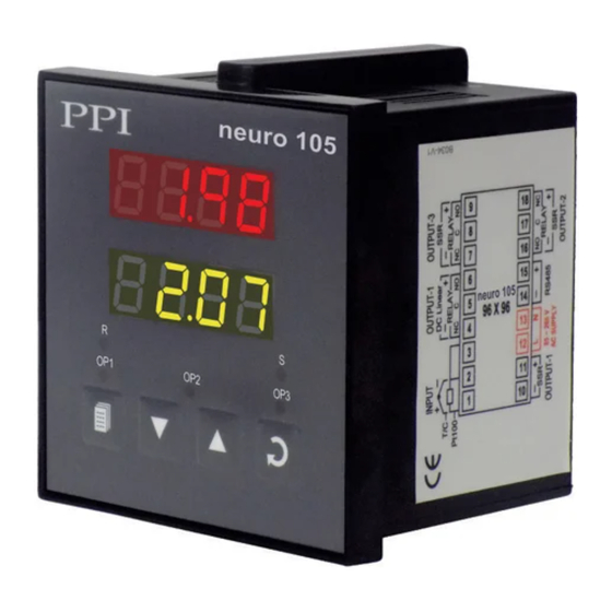
PAGE Key
Fixed
1°C / 1°F
DOWN Key
Symbol
Key
PAGE
Press to enter or exit set-up mode
Press to decrease the parameter value. Pressing once
decreases the value by one count; keeping pressed
DOWN
speeds up the change.
Press to increase the parameter value. Pressing once
User settable
UP
increases the value by one count; keeping pressed
1°C / 1°F
or
speeds up the change.
or
0.1°C / 0.1°F
Press to store the set parameter value and to scroll to the
ENTER
next parameter on the PAGE.
PV Error Indications
Message
User settable
-1999 to +9999 units
1 / 0.1 / 0.01/
0.001 units
NOTE : For Page 17 Kindly Refer the Detailed Manual on
www.ppiindia.net
101, Diamond Industrial Estate, Navghar,
Vasai Road (E), Dist. Palghar - 401 210.
T: 0250 - 2391722/33/37/42
M: 07498799226
09321985369
E:
sales@ppiindia.net,
support@ppiindia.net
Front Panel
neuro 105
Ramp Indicator
R
S
Soak Indicator
OP1
OP2
OP3
Output-3 Indicator
ENTER Key
UP Key
Keys Operation
Function
.
PV Error Type
Over-range
(PV above Max. Range)
Under-range
(PV below Min. Range)
Open
(Sensor open / broken)
Advertisement
Table of Contents

Related Manuals for PPI neuro 105


Summary of Contents for PPI neuro 105
- Page 1 Operation Manual neuro 105 48X48 This brief manual is primarily meant for quick reference to wiring Programmable Profile Controller connections and parameter searching. For more details on operation and application; please log on to www.ppiindia.net INPUT / OUTPUT PARAMETERS : PAGE 12...
- Page 2 JUMPER SETTINGS MOUNTING DETAILS MOUNTING DETAILS ELECTRICAL CONNECTIONS OUTPUT-2 & OUTPUT-3 OUTPUT-2 MODULE OUTPUT-3 MODULE Plug & Socket Connector Plug & Socket Connector Output OUTPUT 2 Module Output RELAY Module SSR / DC Linear Projected Projected Parts Parts +12V / +5V Relay/SSR Module INPUT CPU Board...
- Page 3 Operation Manual neuro 105 96X96 This brief manual is primarily meant for quick reference to wiring Programmable Profile Controller connections and parameter searching. For more details on operation and application; please log on to www.ppiindia.net INPUT / OUTPUT PARAMETERS : PAGE 12...
- Page 4 ELECTRICAL CONNECTIONS SERIAL COMMUNICATION MODULE Output 3 Jumper Setting Power-Supply 8 Pin Female Socket Serial Communication Module 8 Pin Male Plug 96 X 96 INPUT & OUTPUT HARDWARE JUMPER SETTINGS Input Output-2 Display Input Type Jumper ‘A’ Setting Output Type Jumper Setting - D Jumper Setting - E Thermocouple,...
Need help?
Do you have a question about the neuro 105 and is the answer not in the manual?
Questions and answers