
Related Manuals for PPI Zenex Plus


Summary of Contents for PPI Zenex Plus
- Page 1 Zenex Plus Zenex Plus User Manual Multi-Purpose Temperature Controller with Graphic Display User Manual...
-
Page 2: Table Of Contents
Zenex Plus User Manual CONTENTS 1. FRONT PANEL LAYOUT 2. BASIC OPERATION 3. OPERATOR PARAMETERS 4. SUPERVISORY PARAMETERS 5. FACTORY PARAMETER 6. PANEL MOUNTING AND ELECTRICAL CONNECTIONS... -
Page 3: Front Panel Layout
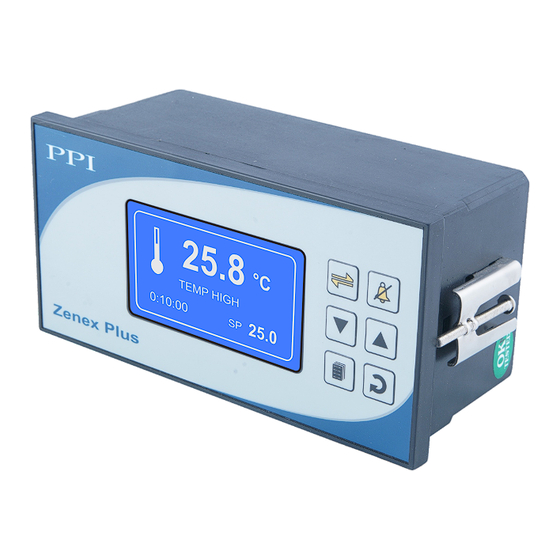
Zenex Plus User Manual Section 1 FRONT PANEL LAYOUT The Controller front panel comprises of Graphic Readout and Membrane Keys as shown in Figure 1.1 below. Figure 1.1 25.8 Graphic °C Readout Keys TEMP HIGH 25.0 0:10:00 Zenex Plus GRAPHIC READOUT... -
Page 4: Basic Operation
Zenex Plus User Manual Section 2 BASIC OPERATIONS Figure 2.1 POWER-UP DISPLAY Upon power-up the controller displays model name, Hardware Version H/W Version and Software Version for 2 seconds as shown in figure 2.1. S/W Version RUN MODE After the Power-up display the controller enters into RUN Mode. This is the normal operation mode wherein the controller starts PV measurements, Alarm monitoring and Control Loop execution. - Page 5 Zenex Plus User Manual The Alarm / Process Status space on the screen may show one or more of the several messages listed in Table 2.2 depending upon the existence of active alarms or process events. In case of co-existence of multiple active alarms or process events, the messages are scrolled one after the other with an approximate time interval of 3 seconds.
- Page 6 Zenex Plus User Manual Figure 2.5 (a) The Controller provides programmable Low & High deviation limits around the temperature control setpoint to monitor Alarm Figure 2.5 (b) Temperature Alarm Status conditions. The screen shows either Normal or Low or High...
-
Page 7: Operator Parameters
Zenex Plus User Manual Section 3 OPERATOR PARAMETERS The Operator Parameters are accessible under PASSWORD 0. The list includes parameters for adjusting Control Setpoint, Alarm Setpoints & Zero-offset. If Timer is enabled then Time Interval value & Timer Start / Abort commands are also available. - Page 8 Zenex Plus User Manual Settings Parameter Description (Default Value) CTRL SET VALUE >> Setpoint LO limit to Setpoint HI limit This parameter sets the value at which the controller atte mpts maintain the measured temperature value. (Default : 25.0) LO DEVIATION >>...
-
Page 9: Supervisory Parameters
Zenex Plus User Manual Section 4 SUPERVISORY PARAMETERS The various parameters have been assembled in different groups under the default factory password 123. Refer Table 4.1 below for a quick summary of parameters under different groups. Each parameter has been described in subsequent sections. - Page 10 Zenex Plus User Manual Notes The Last Parameter in the selected Group rolls back to the ‘SELECT GROUP’ screen again to avoid re-entering the password in case parameters under multiple groups need to be set. Parameter Descriptions The various Supervisory Parameters have been described with their respective group & sub-group.
- Page 11 Zenex Plus User Manual SUPERVISORY CONTROL Settings Parameter Description (Default Value) TUNE >> (Available for Heat Only / Heat+Cool Control Strategy) (Default : No) Set ‘Yes’ to activate and ‘No’ to abort the Tuning operation. SETPOINT LO LIMIT >> For Thermocouple Input :...
- Page 12 Zenex Plus User Manual Heat + Cool Heat + Cool Heat Only Control Control Zone : Single Control Zone : Dual CZ PROP BAND >> PROPORTIONAL BAND >> PROPORTIONAL BAND >> Proportional Band for Cool Pre-dominant zone 0.1 to 999.9 0.1 to 999.9...
- Page 13 Zenex Plus User Manual PROPORTIONAL BAND Sets proportional gain (% power per unit error). Defined in same units and resolution as that for PV. INTEGRAL TIME Sets integral time constant in Seconds. Setting the value to 0, cuts-off the integral action.
-
Page 14: Factory Parameter
Zenex Plus User Manual Section 5 FACTORY PARAMETERS The various parameters have been assembled in various group under the default factory password 321. Refer Table 5.1 below for a quick summary of parameters under different groups. Each parameter has been described in subsequent sections. - Page 15 Zenex Plus User Manual Parameter Descriptions The various Factory Parameters have been described with their respective group & sub-group. FACTORY CONTROL SENSOR INPUT Settings Parameter Description (Default Value) INPUT TYPE >> Refer Table 5.2 Select Input type in accordance with the type of Temperature (Default : RTD Pt100) sensor (Thermocouple / RTD) connected for measurement.
- Page 16 HEAT COOL SELECT The PPI “Multi-Purpuse Temperature Controller” provides control outputs for driving, both, heating & cooling sources. The user can enable any one or both outputs depending upon the test equipment type and application. If both outputs are enabled (by setting the parameter ‘Control Strategy’...
- Page 17 Zenex Plus User Manual Figure 5.2 70°C Temp. Control SP in Heat Pre-dominant Zone 50°C Boundary Set-point 45°C 30°C Temp. Control SP in Cool Pre-dominant Zone 0°C Compressor Status The zone at and above the boundary SP ( ) is referred as Heat Pre-dominant zone and that below the boundary SP is referred as Cool Pre-dominant zone.
- Page 18 Zenex Plus User Manual Once the air temperature falls below Compressor Switch-ON Level by an amount set by the parameter 'Compressor Hysteresis', the compressor is turned OFF. That is; Compressor Switch - OFF Level = (Compressor Switch-ON Level) – (Compressor Hysteresis) The hysteresis inserts a dead band between the Compressor Switch-ON Level and Compressor Switch-OFF Level to avoid frequent switching of the compressor.
- Page 19 Zenex Plus User Manual Table 5.2 Settings Parameter Description (Default Value) CONTROL STRATEGY >> Heat Only Used in applications like Heating Oven, Vacuum Oven, Muffle Furnace, etc.; that require raising the temperature above ambient. (Heater) control output switches ‘heating source’ for maintaining the temperature at desired setpoint.
- Page 20 Zenex Plus User Manual FACTORY TIMER PARAMETERS Settings Parameter Description (Default Value) ENABLE >> Timer function and Start / Abort commands are enabled. (Default : No) Timer function and Start / Abort commands are disabled. START BAND >> 0 to 999.9...
- Page 21 Zenex Plus User Manual FACTORY DOOR OPEN Settings Parameter Description (Default Value) ENABLE >> Set to ‘Yes’ if Switch is mounted for detecting door Open / Close position. (Default : NO) SWITCH LOGIC >> Close : Door Open CLOSE : DOOR OPEN...
- Page 22 Zenex Plus User Manual FACTORY EXIT Parameter Description EXIT SETUP MODE >> Select to quit Setup mode and return to Main Display mode.
-
Page 23: Panel Mounting And Electrical Connections
Zenex Plus User Manual Section 6 PANEL MOUNTING AND ELECTRICAL CONNECTIONS WARNING MISHANDLING / NEGLIGENCE CAN RESULT IN PERSONAL DEATH OR SERIOUS INJURY. PANEL CUTOUT Figure 6.1(a) : Old Version Figure 6.1(b) : New Version Panel Cutout Panel Cutout 75 X 152 mm 75 X 150 mm -0, +1.0 mm... - Page 24 Zenex Plus User Manual Figure 6.2(a) : Old Version Pt100 RS485 Serial Door Open Timer Start Supply Heater Compressor Process Event 85 ~ 264 Alarm ACK Control Control Alarm Alarm Figure 6.2(b) : New Version AI-1 : Process Sensor SERIAL COMM...
- Page 25 Zenex Plus User Manual DIGITAL OUTPUTS Heater Control Output Compressor Control Output Process Alarm Output Event Alarm Output All the above Control & Alarm outputs are Voltage pulses (12VDC @ 40mA) for driving external SSR or Relay. The ‘+’ and ‘-’...
- Page 26 Zenex Plus User Manual POWER SUPPLY As standard, the module is supplied with power connections suited for 8 to 264 VAC line supply. Use well-insulated copper conductor wire of the size not smaller than 0.5mm² for power supply connections ensuring proper polarity as shown in Figure 6.7.
- Page 27 Zenex Plus User Manual Process Precision Instruments 101, Diamond Industrial Estate, Navghar, Vasai Road (E), Dist. Palghar - 401 210.Maharashtra, India 0250 - 2391722/33/37/42 07498799226, 09321985369 sales@ppiindia.net, support@ppiindia.net w w w . p p i i n d i a . n e t...
Need help?
Do you have a question about the Zenex Plus and is the answer not in the manual?
Questions and answers