
Related Manuals for PPI FLOREX


Summary of Contents for PPI FLOREX
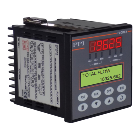
- Page 1 FLOREX Flow Rate Indicator Cum Totaliser F L O W T O T A L . 6 8 2 1 8 9 2 5 User Manual...
-
Page 2: Table Of Contents
FLOREX User Manual CONTENTS PANEL MOUNTING AND ELECTRICAL CONNECTIONS FRONT PANEL : LAYOUT AND OPERATION PAGES AND PARAMETERS FLOW ALARM PARAMETERS TOTAL ALARM PARAMETERS RETRANSMISSION PARAMETERS INPUT CONFIGURATION PARAMETERS SUPERVISORY PARAMETERS SERIAL CONFIGURATION PARAMETERS 10. UTILITY PARAMETERS 11. USER LINEARISATION PARAMETERS 12. -
Page 3: Panel Mounting And Electrical Connections
FLOREX User Manual Section 1 FRONT PANEL LAYOUT The FLOREX front panel comprises of digital readouts, LED indicators and membrane keys as shown in Figure 1.1 below. Figure 1.1 Upper Readout Alarm-1 Rate Indicator Alarm-2 TotaI Indicator Alarm-2 Rate Indicator... - Page 4 • Remains OFF while the Flow Total value is less than the set Total value. KEYS There are eight tactile keys provided on the front panel for configuring the FLOREX selecting View Only parameters, setting- up the program Mode and selecting Operation Parameters.
-
Page 5: Front Panel : Layout And Operation
Flow Rate Indication The Florex accepts DC Linear Current / Voltage Input from the Flowmeters to measure the Flow Rate. The value of the Flow Rate is displayed in accordance with the value for Range Low / High and the Resolution selected on Input Configuration Page. - Page 6 3. Press ENTER key to Reset the Total value to 0. Notice that upon resetting the Flow Total to 0, the FLOREX immediately starts accumulating the Flow Total if the Flow Rate is other than 0. If the set Passcode value does not match with the value set for the Supervisory Passcode set on Utility Page, the FLOREX reverts to MAIN Display Mode without resetting the accumulated Total.
- Page 7 Alarm Acknowledgment The FLOREX is provided with the output (Relay/SSR) facilitating “hard” alarm for Flow Rate as well as Flow Total. That is, if any or both the alarms are activated (alarm condition is occurred), the output (Relay/SSR) associated with their respective alarms gets energized and sounds the buzzer/hooter.
- Page 8 FLOREX will continue to view the actual counts stored at the instant Flow Rate Error condition occurred. If the power supply to the FLOREX is switched-off or a power-failure occurs while the Storage of Minimum & Maximum value of Flow...
- Page 9 UP/DOWN and ENTER key. Step through the followings to adjust the Operator Parameter values. 1. While the FLOREX is in MAIN Display Mode, press and release the OPERATOR key. The Lower Readout displays the first -parameter in the list.
- Page 10 FLOREX User Manual Settings Parameter Description (Default Value) PASSCODE VALUE This parameter is available and applicable only if the ‘Reset Command’ for ‘Storage of Minimum & Maximum value of Flow Rate’ is set to ‘Yes’ on Operator Page. The numeric value entered for this parameter should match with the numeric value set for the ‘Supervisory Passcode’...
- Page 11 FLOREX User Manual Settings Parameter Description (Default Value) TOTAL ALARM-1 SETPOINT This parameter is available only if ‘Total Alarm-1’ is selected to 0 to 99999999 ‘Enable’. If enabled, the alarm is activated whenever the (Default : 5000000) accumulated Flow Total is at or above the Total Alarm-1 Setpoint.
-
Page 12: Pages And Parameters
PAGES AND PARAMETERS ORGANIZATION The FLOREX requires various user settings that determine how the FLOREX will function or operate. These settings are called Parameters. The parameters are always presented in a fixed format: The Upper Row of Lower Readout displays the parameter name (Identification Tag) and the Lower Row displays the options / set value. - Page 13 MAIN Display Mode (by depressing PAGE key) without pressing the ENTER key will not store the altered value in the FLOREX memory and the previous set value will be retained. Also, if the power failure occurs prior to pressing ENTER key, upon resumption of power, the FLOREX reverts to MAIN Display Mode without storing the altered value and retaining the previous set value.
- Page 14 9. Notice that it requires setting Lock to ‘Yes’ once for Locking but twice for Unlock. Also, for Unlock, the setting to ‘Yes’ must be entered twice during the same duration for which the FLOREX is powered. That is, setting ‘Yes’ once prior to power loss and once after resumption of power shall not Unlock.
- Page 15 FLOREX User Manual Figure 3.3 SELECT FLOREX>> TOTAL FLOW>> Default Setting S/W:1 H/W:1 18925682 Power-On MAIN Display Reset Display Mode Note: Notice that after carrying out the “Setting Default Value” procedure, all the resolution based parameters (like Flow Rate, Flow Total, ‘Alarm Setpoint’, ‘Alarm Hysterisis, ’User Offset’...
-
Page 16: Flow Alarm Parameters
FLOW ALARM PARAMETERS The Alarm Parameters are grouped on Flow Alarm Page. The FLOREX is provided with 2 independent “soft” alarms, that is, the alarms can be set and generated even if the corresponding output modules are not fitted or assigned to other function. The front panel indicators AL1 and AL2 for RATE indicate the alarm statuses. - Page 17 FLOREX User Manual Settings Parameter Description (Default Value) 0 to 30000 ALARM-2 SETPOINT (Default : (Available for Process High or Process Low Alarm-2 Type) For Process Low: 0, Sets Alarm limit independent of control setpoint. For Process High: 1000) ALARM-2 HYSTERESIS...
-
Page 18: Total Alarm Parameters
TOTAL ALARM PARAMETERS The Total Alarm Parameters are grouped on Total Alarm Page. The FLOREX is provided with 2 independent “soft” alarms, that is, the alarms can be set and generated even if the corresponding output modules are not fitted or assigned to other function. - Page 19 FLOREX User Manual Settings Parameter Description (Default Value) ALARM-2 ACTIVATION Disable Enable Definition same as Alarm-1 but applied to Alarm-2 (Default : Disable) ALARM-2 SET POINT 0 to 99999999 Definition same as Alarm-1 but applied to Alarm-2 (Default : 5000000)
-
Page 20: Retransmission Parameters
0-20 mA, 4-20 mA, 0-5 0 to 5 Volts V or 0- 10 V. The FLOREX outputs a linear 0-20 mA, 4-20 mA, 0-5 0 to 10 Volts V or 0-10 V signal, through the optional DC Linear output, (Default : 0 to 20 mA) proportional to the Flow Rate within ‘Low Range’... -
Page 21: Input Configuration Parameters
Section 7 INPUT CONFIGURATION PARAMETERS The Input Configuration Parameters are grouped on Input Config. Page and allows the user to configure the FLOREX to match with the available input sensor. It also presents the parameters for conditioning the input sensor signal. - Page 22 FLOREX User Manual Settings Parameter Description (Default Value) FILTER CONSTANT 0.0 to 60.0 Sets the time constant, in seconds, for the low-pass digital filter applied to the measured PV. The filter helps smoothing / (Default : 0.5 sec.) averaging the signal input and removing the undesired noise.
- Page 23 FLOREX User Manual Table 7.2 0 to 20 mA 0 to 20 mA DC current 4 to 20 mA 4 to 20 mA DC current 0 to 50 mV DC voltage 0 to 50 mV User settable 0 to 200 mV DC voltage...
-
Page 24: Supervisory Parameters
Section 8 SUPERVISORY PARAMETERS The Supervisory Parameters are grouped on Supervisory Page and pertain to the FLOREX’s supervisory utility features to exercise the supervisory control over the operator level. The Table 8.1 below lists the parameters required for the operations of the supervisory utility features followed by definition of each parameter. -
Page 25: Serial Configuration Parameters
Section 9 SERIAL CONFIGURATION PARAMETERS The Serial Configuration Parameters are grouped on Serial Config. Page and allows the user to configure the FLOREX to communicate with master devices like PC or Digital Recorders. The Digital (Serial) communications facilitate the FLOREX to communicate with a Master Device like Digital Recorder or PC via MODBUS (RTU) protocol, if hardware module (RS 485 / RS 232) is fitted. -
Page 26: Utility Parameters
Section 10 UTILITY PARAMETERS The Utility Parameters are grouped on Utilities Page and allows the user to access the various Utilities of the FLOREX such as Locking/Unlocking, Supervisory Passcode, Default Setting, Factory Cal. Regain, User Calibration and User Linearisation. The Navigation Diagram below lists the various Utility Parameters required for accessing the various utilities of the FLOREX. -
Page 27: User Linearisation Parameters
Supervisory Passcode The access to this parameter is allowed only if the FLOREX is Unlocked. The numeric value set for this paramete under supervisory level is a secret code that is commonly applicable for both Total Reset Command and Min./Max. Reset Command. - Page 28 Flow Rate (i.e. 50), if the user derived value is set to 60, the FLOREX will display the Flow Rate of 60 instead of 50 when it receives the Input Signal of 10 mA.
-
Page 29: Hardware Assembly & Configuration
FLOREX User Manual Section 12 HARDWARE ASSEMBLY AND CONFIGURATIONS The Figure 12.1 below shows the indicator outer-case viewed with front label upright. Figure 12.1 Ventilations Panel Mounting Clamp Bezel Rear Terminals Enclosure Front Label Pullout Connection Diagram Latch ELECTRONIC ASSEMBLY The basic electronics assembly (without any plug-in modules), comprises of 4 Printed Circuit Boards (PCB). - Page 30 FLOREX User Manual Removing Assembly from Enclosure Hold the indicator upside down and press the pullout latch to unlock the front bezel from the enclosure (Refer Figure 12.2 above). Pull the bezel outward. The electronics assembly comes out with the bezel.
- Page 31 FLOREX User Manual Table 12.1 Output-1 Jumper Settings Output Type Jumper Setting - B Jumper Setting - C Relay SSR Drive DC Linear Current (or Voltage) OUTPUT PLUG-IN MODULES (OP2, OP3,OP4 & OP5) The indicator supports 3 types of ‘Plug-in Modules’ that can be used as outputs (OP2, OP3, OP4 & OP5).The 3 types are; (a) Relay /SSR Module, (b) DC Linear Voltage Module and (c) DC Linear Current Module.
- Page 32 FLOREX User Manual Figure 12.5(b) Mounting Parts for Output Modules 5-Pin Male Plug 4-Pin Male Plug 5-Pin Male Plug CPU PCB Output PCB 4-Pin Male Plug Figure 12.6 Power-Supply CPU PCB Output PCB...
- Page 33 FLOREX User Manual Each Module is provided with one 4-Pin & one 5-Pin Female Socket that can directly fit into corresponding male plugs provided on either Output PCB (OP2, OP3 & OP4) or CPU PCB (OP5). Refer Figure12.5(a) & 12.5(b). These modules are either pre- fitted while the indicator is shipped from the factory or can be fitted later by the user.
- Page 34 FLOREX User Manual Figure 12.8 DC Voltage/Current Module Serial Communication Plug-in Module The 4-Pin Male Plug for mounting the Serial Communication Module is located on the Power-supply PCB, as shown in the Figure 12.9 below. The Serial Communication Module is provided with a 4-Pin female sockets on the bottom side for the mounting purpose.
-
Page 35: Mechanical Installation
FLOREX User Manual Section 13 MECHANICAL INSTALLATION The following precautions should be strictly observed while installing the indicator: 1. The place of installation should be free of corrosive/combustible gases and electrically conductive pollution. 2. Ensure that the place of installation is not subject to rapid ambient changes that can cause condensation. Also the Ambient Temperature and Relative Humidity surrounding the indicator should not exceed the maximum specified for the proper operation of the indicator. - Page 36 FLOREX User Manual 3. Insert the rear of the indicator housing through the panel cutout from the front of the mounting panel. 4. Hold the indicator gently against the mounting panel such that it positions squarely against the panel wall (see Figure 13.3).
-
Page 37: Electrical Connections
The Electrical Connection Diagram is shown on the left side of the FLOREX enclosure. The diagram shows the terminals viewed from the REAR SIDE with the FLOREX label upright. Note that the Alarm Outputs and the Serial Comm. are applicable only if the respective plug-in modules are fitted. - Page 38 DESCRIPTIONS The back panel connections are described as under: INPUT (Terminals 31 and 32) The FLOREX accepts DC Linear Current/Voltage (mV,V,mA) as input from Flowmeters. The types and ranges are described in Section 6 : Retransmission Parameters. Figure 14.2 DC linear mV / V / mA Use a shielded twisted pair with the shield grounded at the signal source for connecting DC Linear Voltage (mV / V) source.
- Page 39 0.5mm² for power supply connections. Connect Line (Phase) supply line to terminal 1 and the Neutral (Return) supply line to terminal 2 as shown in Figure 14.5 above. The FLOREX is not provided with fuse and power switch.
- Page 40 Do not use redundant wires in communication cables for other signals. Ensure that the cable is ‘daisy chained’ between FLOREXs for multi-dropped wiring. That is, run from one FLOREX to the next to the final FLOREX in the chain.
- Page 41 Process Precision Instruments 101, Diamond Industrial Estate, Navghar, Vasai Road (E), Dist. Palghar - 401 210.Maharashtra, India 0250 - 2391722/33/37/42 07498799226, 09321985369 sales@ppiindia.net, support@ppiindia.net w w w . p p i i n d i a . n e t...
Need help?
Do you have a question about the FLOREX and is the answer not in the manual?
Questions and answers