Advertisement
HumiTherm Plus
HumiTherm Plus for PC
Micro PLC Based Temperature + Humidity (%RH)
21 CFR Part 11 Compliant PC Software
Masters Configuration
Configuration Online Summary
History View
Select Option
Device Wise
Device/Group
HumiLog
Online Device Comm. Status
Device Comm. Status
1- Humilog - Comm. Success
Offline Device Comm. Status
Device Comm. Status
1- Humilog - IDEAL
Control & Recording System with
x
HumiLog
Analysis Report
Alarm (4)
Data Download
User Master
Info
Exit
Log Out
admin
Online Graph
Y-Axis Text
Parameter
Color
MIN
Graph Refresh
Interval
PV_C
default
Parameter
PV_RH
default
MAX
2
Close
Show/Hide
Ledgends
Scale Y Max
Set Interval
08-05-2015 15:17:59
Parameter
PV
Low Alarm
High Alarm
Low Alarm SP
High Alarm SP
Control SP
Water Low Level Alarm
Channel Name
C
RH
User Manual
User Manual
Advertisement

Related Manuals for PPI HumiTherm Plus


Summary of Contents for PPI HumiTherm Plus
- Page 1 HumiTherm Plus HumiTherm Plus for PC User Manual Micro PLC Based Temperature + Humidity (%RH) Control & Recording System with 21 CFR Part 11 Compliant PC Software HumiLog Masters Configuration Configuration Online Summary History View Analysis Report Alarm (4) Data Download...
-
Page 2: Table Of Contents
HumiTherm Plus for PC User Manual CONTENTS 1. FRONT PANEL LAYOUT 2. BASIC OPERATION 3. OPERATOR PARAMETERS 4. RECORDING PARAMETERS 5. FACTORY PARAMETERS 6. PANEL MOUNTING AND ELECTRICAL CONNECTIONS APPENDIX-A : DC LINEAR SIGNAL INTERFACE... -
Page 3: Front Panel Layout
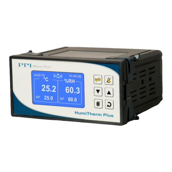
HumiTherm Plus for PC User Manual Section 1 FRONT PANEL LAYOUT The Controller front panel comprises of Graphic Readout and membrane keys as shown in Figure 1.1 below. Figure 1.1 Micro PLC Graphic 3/02/15 10:40:06 °C Readout 25.2 60.3 Keys 25.0... -
Page 4: Basic Operation
HumiTherm Plus for PC User Manual Section 2 BASIC OPERATIONS POWER-UP DISPLAY Figure 2.1 (a) Figure 2.1 (b) Self Checking... HumiTherm Plus REAL TIME CLOCK H/W Version 01.01 SD MEMORY CARD COMM. LINK F/W Version 01.01 EEPROM Upon power-up the controller display shows screen depicted in Figure 2.1(a) for 2 Seconds. The controller runs through a self- test sequence for checking its Real Time Clock, SD Memory Card, internal Communication Link and Parameter Storage Memory (EEPROM). - Page 5 HumiTherm Plus for PC User Manual In case of measured value errors for %RH (Sensor disconnected or output value below or above specified range), the measured values are restricted to 0% or 100% depending on signal values. The ‘Alarm / Status’ space on the screen may show one of the 3 icons listed in Table 2.2 depending upon the existence of condition.
- Page 6 HumiTherm Plus for PC User Manual Humidity Alarm Status The Controller provides programmable Low & High deviation limits around the Humidity control setpoint to monitor Alarm conditions. The screen shows either NORMAL or LOW or HIGH Status, as shown in Figure 2.5 (b) depending upon the deviation of measured %RH value from the control setpoint and set limits.
-
Page 7: Operator Parameters
HumiTherm Plus for PC User Manual Section 3 OPERATOR PARAMETERS The Operator Parameters are accessible under PASSWORD 0. The list includes Parameters for adjusting Control setpoints, Alarm setpoints & Zero-offset for Temperature & %RH. The Figure 3.1 shows how to access Operator Parameters. The Example illustrates changing the setpoint value for %RH from 60.0 to 70.0. - Page 8 HumiTherm Plus for PC User Manual Settings Parameter Description (Default Value) TEMP. LO DEVIATION >> This Parameter sets a negative deviation (offset) limit with respect 0.2 to 99.9 to the ‘Control Set-point’ for Temperature. The Alarm is activated if (Default : 2.0)
-
Page 9: Recording Parameters
HumiTherm Plus for PC User Manual Section 4 RECORDING PARAMETERS The Recording Parameters are accessible under PASSWORD 123. The list includes Parameters for adjusting Recording interval, Setting Real Time Clock (RTC), Deleting Records, etc. The Figure 4.1 shows how to access Recording Parameters. The Example illustrates changing the Recording Interval (first parameter in the list) from 5 Minutes to 30 Minutes. - Page 10 HumiTherm Plus for PC User Manual Settings Parameter Description (Default Value) TEMP. ZERO OFFSET >> This value is algebraically added to the measured Temperature -50.0 to 50.0 Value to derive the final Value that is displayed and compared for alarm / control. Use this value to nullify any known constant error.
-
Page 11: Factory Parameters
HumiTherm Plus for PC User Manual Section 5 FACTORY PARAMETERS The various parameters have been assembled in groups and sub-groups under the password 321. Refer Table 5.1 below for a quick summary of parameters under different groups & sub-groups. Each parameter has been described in subsequent sections. - Page 12 HumiTherm Plus for PC User Manual Accessing Group/Sub-group & Parameters The Figure 5.1 below illustrates how to access the group/sub-group and parameters. The example shows changing the value for the parameter ‘Proportional Band’ for Humidity Control that is located under group ‘Humidity Settings’ & sub-group ‘Control’.
- Page 13 HumiTherm Plus for PC User Manual For convenience this Temperature Settings group is further divided into 3 sub-groups : Alarm Parameters, Control Parameters & Sensor Input Parameters. FACTORY TEMPERATURE ALARM Settings Parameter Description (Default Value) HYSTERESIS >> 0.1 to 99.9...
- Page 14 HumiTherm Plus for PC User Manual Settings Parameter Description (Default Value) Control Zones : Dual CZ PROP BAND >> 0.1 to 999.9 Sets proportional gain for Cool Pre-dominant zone. (Default : 50.0 CZ INTEGRAL TIME >> 0 to 3600 Sec...
- Page 15 HumiTherm Plus for PC User Manual FACTORY TEMPERATURE SENSOR INPUT Settings Parameter Description (Default Value) INPUT TYPE >> RTD Pt100 0-20mA Select Input type in accordance with the type of Temperature 4-20mA sensor / transmitter connected for measurement. 0-5V 0-10V...
- Page 16 HumiTherm Plus for PC User Manual For convenience this Humidity (%RH) Settings group is further divided into 3 sub-groups : Alarm Parameters, Control Parameters & Sensor Input Parameters. FACTORY HUMIDITY (%RH) ALARM Settings Parameter Description (Default Value) HYSTERESIS >> 0.1 to 99.9...
- Page 17 HumiTherm Plus for PC User Manual Settings Parameter Description (Default Value) Control Zones : Dual CZ PROP BAND >> 0.1 to 999.9 Sets proportional gain for Cool Pre-dominant zone. (Default : 50.0 CZ INTEGRAL TIME >> 0 to 3600 Sec...
- Page 18 HumiTherm Plus for PC User Manual FACTORY HUMIDITY (%RH) SENSOR INPUT Settings Parameter Description (Default Value) INPUT TYPE >> 0-20mA 4-20mA Select Input type in accordance with the type of %RH sensor / 0-5V transmitter connected for measurement. 0-10V 1-5V (Default : 0-5V) SIGNAL LO >>...
- Page 19 FACTORY COMPRESSOR Compressor Switching Strategies The PPI “Temperature + Humidity” composite controllers offer different programmable strategies for compressor switching to meet different design approaches by the manufacturers of Humidity Chambers. The various strategies and the implementations are described here. 1. Compressor Off The compressor is kept Off.
- Page 20 HumiTherm Plus for PC User Manual 4. PV Based Strategy In this strategy, the compressor is switched to cool down the chamber air temperature. The controller switches the compressor ON or OFF based on the comparison between the chamber temperature value and the Temperature SP.
- Page 21 HumiTherm Plus for PC User Manual The figure 5.4 above illustrates 3 cases. Case (1) illustrates power-up delay. In case (2); the time elapses before PV rises above the SP. The compressor is thus switched ON as soon as the PV rises above the SP. In case (3); the PV rises above the SP while the time delay is still in progress.
- Page 22 HumiTherm Plus for PC User Manual FACTORY BOILER WATER LEVEL Settings Parameter Description (Default Value) ENABLE >> Set to ‘Yes’ if water level Sensor(s) is mounted for detecting Low water level. (Default : WATER LEVEL STARTEGY >> Single Switch A single float type sensor is installed for detecting low water level.
- Page 23 HumiTherm Plus for PC User Manual FACTORY DOOR OPEN Settings Parameter Description (Default Value) ENABLE >> Set to ‘Yes’ if Switch is mounted for detecting door Open / Close position. (Default : SWITCH LOGIC >> Close : Door Open CLOSE : DOOR OPEN The Door position is considered Open if the switch is CLOSE.
- Page 24 HumiTherm Plus for PC User Manual FACTORY SMS ALERT The ‘SMS ALERT’ group is available only if the controller is supplied with GSM Module Version. Settings Parameter Description (Default Value) ENABLE >> Set this parameter to ‘No’ if GSM module is not attached or SMS alerts are not required.
-
Page 25: Panel Mounting And Electrical Connections
HumiTherm Plus for PC User Manual Section 6 PANEL MOUNTING AND ELECTRICAL CONNECTIONS WARNING MISHANDLING / NEGLIGENCE CAN RESULT IN PERSONAL DEATH OR SERIOUS INJURY. PANEL CUTOUT Figure 6.1 Panel Cutout 78 X 154 mm -0, +0.5 mm PANEL MOUNTING Follow the steps below for mounting the instrument on panel : 1. - Page 26 HumiTherm Plus for PC User Manual Figure 6.2 Pt100 5V 24V COMMON mV/V BATTERY WATER LEVEL S/W - 1 Excitation mV/V DOOR WATER LEVEL S/W - 2 °C RS485 COMM 18~32VDC HumiTherm Plus 32 31 30 29 28 27 26 25 24 23 22...
- Page 27 HumiTherm Plus for PC User Manual Figure 6.4 (a) Humidity (%RH) Transmitter Input (Terminals : 12,13, 14) 0/1~5V, 0~10V The Controller accepts DC Current (mA) / DC Voltage (V) as Humidity input. The connections are 12 13 14 described below.
- Page 28 HumiTherm Plus for PC User Manual The controller Communication Port is RS485 and requires a similar port at the host (master) end. If, however, the host port is different (say, RS232), use appropriate protocol converter (say, RS485-RS232) for interface. For reliable noise free communication, use a pair of twisted wires inside screened cable as shown in Figure .
-
Page 29: Appendix-A : Dc Linear Signal Interface
(mV/V/mA) and Range. Most PPI instruments, thus, provide programmable Signal Type and Range to facilitate interface with a variety of transmitters. A few industry standard signal types and ranges offered by the PPI instruments are: 0-50mV, 0- 200mV, 0-5 V, 1-5 V, 0-10V, 0-20 mA, 4-20 mA, etc. - Page 30 HumiTherm Plus for PC User Manual The following examples illustrate appropriate parameter value selections. Example 1: Pressure Transmitter producing 4 to 20 mA 0 to 5 psi Y (psi) Presume the pressure is to be measured Range High 5.00 with 0.01 Resolution, that is 0.00 to 5.00 psi.
- Page 31 HumiTherm Plus for PC User Manual Process Precision Instruments 101, Diamond Industrial Estate, Navghar, Vasai Road (E), Dist. Palghar - 401 210.Maharashtra, India 0250 - 2391722/33/37/42 07498799226, 09321985369 sales@ppiindia.net, support@ppiindia.net w w w . p p i i n d i a . n e t...
Need help?
Do you have a question about the HumiTherm Plus and is the answer not in the manual?
Questions and answers