
Related Manuals for PPI neuro 102L Plus


Summary of Contents for PPI neuro 102L Plus
- Page 1 102L Plus neuro 102V Plus Universal Single Loop Process Controllers User Manual...
-
Page 2: Table Of Contents
neuro 102 Plus User Manual CONTENTS FRONT PANEL LAYOUT BASIC OPERATION SET-UP MODE ACCESS AND OPERATION CONTROL PARAMETERS ALARM PARAMETERS CONFIGURATION PARAMETERS SUPERVISORY PARAMETERS PROFILE PARAMETERS OP2 & OP3 FUNCTION PARAMETERS USER LINEARISATION PARAMETERS HARDWARE ASSEMBLY & CONFIGURATIONS 12. MECHANICAL INSTALLATION 13. -
Page 3: Front Panel Layout
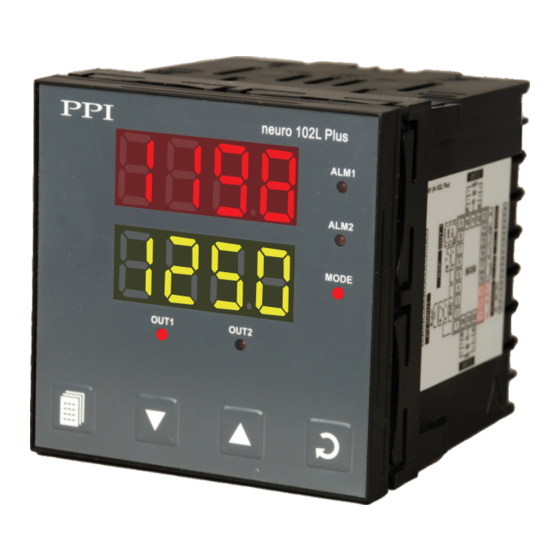
OUT2 MODE Operation Mode Output-1 Status Indicator Output-2 Status PAGE Key ENTER Key DOWN Key UP Key Figure 1.1 (b) : neuro 102L Plus neuro 102L Plus ALM1 Upper Readout Alarm-1 Indicator ALM2 Alarm-2 Indicator MODE Operation Mode Lower Readout... - Page 4 Glows Green if Auxiliary or Remote Setpoint is Active — Applicable for Model neuro 102V Plus Applicable for Model neuro 102L Plus KEYS There are four tactile keys provided on the front panel for configuring the controller, setting-up the parameter values and selecting Operation Modes.
-
Page 5: Basic Operation
neuro 102 Plus User Manual Section 2 BASIC OPERATION POWER-UP Upon power-up, all displays and indicators are lit on for approximately 3 seconds. This is followed by the indication of the controller model name on the Upper Readout and the firmware version on the Lower Readout, for approximately 1 second. - Page 6 neuro 102 Plus User Manual Auxiliary Set-point Mode Indication (Applicable if controller is supplied with Auxiliary Set-point option) The Controller is supplied with 2 rear panel terminals for connecting remote switch (potential-free contacts) to toggle between Main Control Set-point (SP) & Auxiliary Control Set-point. The “Open”...
- Page 7 neuro 102 Plus User Manual MANUAL MODE OPERATION This operation mode is available only if the control action is PID and if the manual mode operation is permitted at supervisory level. In this mode, the controller operates in Open loop mode wherein the % Output Power is manually adjusted by the operator.
- Page 8 neuro 102 Plus User Manual Accessing Operator Page & Adjusting Parameters Step through the following sequence to open the operator page and to adjust the operator parameter values. 1. Press and release PAGE key. The Lower Readout shows (PAGE) and Upper Readout shows (0).
- Page 9 neuro 102 Plus User Manual Settings Parameter Description (Default Value) AUXILIARY CONTROL SETPOINT Setpoint Low Limit (Available only if the Controller is supplied with Auxiliary Set-point to Setpoint High Limit option) (Default : -1999) The alternate control set-point that the controller respects for control purpose when selected through remote input terminals.
-
Page 10: Set-Up Mode Access And Operation
neuro 102 Plus User Manual Section 3 SET-UP MODE : ACCESS AND OPERATION The various parameters are arranged in different groups, called PAGES, depending upon the functions they represent. Each group is assigned a unique numeric value, called PAGE NUMBER, for its access. The parameters are always presented in a fixed format: The Lower Readout displays the parameter prompt (Identification Name) and the Upper Readout displays the set value. - Page 11 neuro 102 Plus User Manual MASTER LOCKING The controller facilitates locking all the PAGES (except Operator PAGE) by applying Master Lock Code. Under Locking, the parameters are available for view only and cannot be adjusted. The Master Lock, however does not lock the operator parameters.
-
Page 12: Control Parameters
neuro 102 Plus User Manual Section 4 CONTROL PARAMETERS : PAGE-10 Refer Table 4.1 for the parameter descriptions and settings. Table 4.1 Settings Parameter Description (Default Value) For DC mA/mV/V : 1 to 9999 counts PROPORTIONAL BAND For Thermocouples/RTD : (Available for PID Control only) 1 to 999 or 0.1 to 999.9 Sets proportional gain (% power per unit error). - Page 13 neuro 102 Plus User Manual Settings Parameter Description (Default Value) PULSE-ON TIME 0.1 to Value set for Pulse Time (Available for Pulsed On-Off Control only) Sets the ON pulse time in seconds for OP1 Relay / SSR output. (Default : 1.0) COOL HYSTERESIS For DC mA/mV/V : 1 to 9999 counts (Available for On-Off or Pulsed On-Off Control with bi-...
- Page 14 neuro 102 Plus User Manual Section 5 ALARM AND RETRANSMISSION (RECORDER) PARAMETERS : PAGE 11 Refer Table 5.1 for parameter description & settings. Table 5.1 Settings Parameter Description (Default Value) ALARM-1 TYPE None Selects the Alarm-1 activation type. Selecting ‘None’ disables the Process Low alarm and suppresses all the related parameters for Alarm-1.
- Page 15 neuro 102 Plus User Manual Settings Parameter Description (Default Value) Min. to Max. Range ALARM-2 SETPOINT specified for the (Available for Process High or Process Low Alarm-2 Type) selected Input Type Sets Alarm limit independent of control setpoint for Alarm-2 (Default : Min or Max Range) Activation.
-
Page 16: Configuration Parameters
neuro 102 Plus User Manual Section 6 INPUT/OUTPUT CONFIGURATION PARAMETERS : PAGE-12 Refer Table 6.1 for parameter description & settings. Table 6.1 Settings Parameter Description (Default Value) CONTROL ACTION On-Off Select appropriate Control Algorithm suited for process Pulse requirement. (Default : PID) Reverse CONTROL LOGIC Select Reverse (heat logic) or Direct (cool logic). - Page 17 neuro 102 Plus User Manual Settings Parameter Description (Default Value) Input Type Settings Default SIGNAL HIGH Signal Low to 20.00 0 to 20 mA 20.00 (Available for DC linear mV/V/mA Inputs only) Signal Low to 20.00 4 to 20 mA 20.00 The transmitter output signal value corresponding to PV RANGE Signal Low to 80.00...
- Page 18 neuro 102 Plus User Manual Table 6.2 Option Range (Min. to Max.) What it means Resolution Type J Thermocouple 0 to +960°C / +32 to +1760°F Type K Thermocouple -200 to +1376°C / -328 to +2508°F Type T Thermocouple -200 to +385°C / -328 to +725°F Type R Thermocouple 0 to +1770°C / +32 to +3218°F Fixed...
-
Page 19: Supervisory Parameters
neuro 102 Plus User Manual Section 7 SUPERVISORY PARAMETERS : PAGE-13 Refer Table 7.1 for parameter description & settings. Table 7.1 Settings Parameter Description (Default Value) SELF-TUNE COMMAND (Available for PID control only) Set to ‘Yes’ to initiate a new tuning cycle or set to ‘No’ to abort a (Default : No) tuning operation in progress. - Page 20 neuro 102 Plus User Manual Settings Parameter Description (Default Value) PROFILE ABORT COMMAND Disable ON PAGE-1 Enable Supervisory control over availability of Profile Abort command on Page-1. ‘Enable’ for availability. (Default : Disable) The Following Serial Communication Parameters are not available if the Controller is ordered with Auxiliary Setpoint Option.
-
Page 21: Profile Parameters
neuro 102 Plus User Manual Section 8 PROFILE PARAMETERS : PAGE-16, PAGE-14, PAGE-1 Note : This Section is applicable only if the Controller is supplied with “Setpoint Profile” option. The profile utility requires profile configuration and profile settings. Also, the controller facilitates on-line alterations of the parameters pertaining to the running segment. - Page 22 neuro 102 Plus User Manual Profile Settings : PAGE-14 Note : The parameters on this page are available only if the profile feature is enabled on Page-16. Use this list of parameters to set individual profile segment for the target setpoint, time interval, holdback type and value. Refer Table 8.2 below.
- Page 23 neuro 102 Plus User Manual Table 8.3 Settings Parameter Description (Default Value) END OF PROFILE ACKNOWLEDGE This parameter is available if Output-2 (OP2) and / or Output-3 (OP3) Relay/SSR is programmed to turn ON as an ‘End Of Profile’ signal. Set this parameter to ‘Yes’ (after end of profile is reached) (Default : No) to acknowledge the alarm and to turn OFF the output.
- Page 24 neuro 102 Plus User Manual Settings Parameter Description (Default Value) SEGMENT BAND VALUE For DC mA/mV/V : 1 to 9999 counts For Thermocouples/RTD : The modified Holdback Band Value is applied immediately on the 1 to 999 or 0.1 to 999.9 current segment.
-
Page 25: Op2 & Op3 Function Parameters
neuro 102 Plus User Manual Section 9 OP1, OP2 & OP3 FUNCTION PARAMETERS : PAGE-15 Refer Table 9.1 for parameter description & settings. Table 9.1 Settings Parameter Description (Default Value) OUTPUT-1 TYPE Relay Select the type in accordance with the hardware configuration for Output-1 (OP1). - Page 26 neuro 102 Plus User Manual Settings Parameter Description (Default Value) Seconds OP2 EVENT TIME UNITS Minutes (Available if OP2 function is End of Profile & OP2 Event Status is set to ‘ON’) Hours Select time units for the parameter ‘OP2 Event Time’. (Default : Seconds) OP2 EVENT TIME (Available if OP2 function is End of Profile &...
- Page 27 neuro 102 Plus User Manual Settings Parameter Description (Default Value) RECORDER OUTPUT TYPE 0 to 20mA 4 to 20mA (Available if OP3 function is Recorder) 0 to 5V Select type for Output-3 (OP3) in accordance with the hardware module fitted. 0 to 10V (Default : 0 to 20mA)
- Page 28 neuro 102 Plus User Manual Section 10 REMOTE SETPOINT PARAMETERS : PAGE-17 Refer Table 10.1 for parameter description & settings. Table 10.1 Settings Parameter Description (Default Value) REMOTE SETPOINT FEATURE ENABLE No (disable) Enable or Disable the Remote Setpoint Feature. Disabling the Yes (enable) feature will suppress all other related parameters.
-
Page 29: Hardware Assembly & Configurations
neuro 102 Plus User Manual Section 11 HARDWARE ASSEMBLY AND CONFIGURATIONS The Figure 11.1(a) & 11.1 (b) below shows the controller outer-case viewed with front label upright. Ventilations Figure 11.1(a) Panel Mounting Clamp Rear Terminals Bezel – – Enclosure Front Label Connection Diagram Pullout Latch... - Page 30 neuro 102 Plus User Manual ELECTRONIC ASSEMBLY The basic electronics assembly (without any plug-in modules), comprises of 3 Printed Circuit Boards (PCB). When viewed from the front; the CPU PCB is to the right, Power-supply PCB is to the left and the Display PCB is behind the bezel. The electronic assembly can be removed from the plastic enclosure and placed back as described and illustrated in Figure 11.2 (a) &...
- Page 31 Linear Voltage or DC Linear Current and can fit in as output-2 or output-3 interchangeably. The Figure 11.3 & 11.4 below illustrate mounting of output-2 & output-3 modules, respectively. Mounting Output-2 Module Figure 11.3 (a) : neuro 102L Plus Plug & Socket Connector...
- Page 32 102 Plus User Manual Mounting Output-3 Module Plug & Socket Connector Projected Parts Figure 11.4 (a) : neuro 102L Plus Slots CPU Board Front Label Upside Down Plug & Socket Connector Projected Parts Slots CPU Board Figure 11.4 (a) : neuro 102V Plus...
- Page 33 neuro 102 Plus User Manual Jumper Settings The Controller Outputs (Output-1, Output-2 & Output-3) can be configured for different types (Relay, SSR, DC Volts & DC Current) that required jumper settings besides appropriate parameter settings. The jumper settings are provided in the form of Pins &...
- Page 34 neuro 102 Plus User Manual Table 11.1 : Output-1 Jumper Settings Jumper Settings Output Type Shorting Link A : Short Pins A1 & A4 Relay Shorting Link B : Park Shorting Link A : Short Pins A3 & A4 SSR Drive Shorting Link B : Short Pins B2 &...
-
Page 35: Mechanical Installation
neuro 102 Plus User Manual Section 12 MECHANICAL INSTALLATION The following precautions should be strictly observed while installing the controller: 1. The place of installation should be free of corrosive/combustible gases and electrically conductive pollution. 2. Ensure that the place of installation is not subject to rapid ambient changes that can cause condensation. Also the Ambient Temperature and Relative Humidity surrounding the controller should not exceed the maximum specified for the proper operation of the controller. - Page 36 neuro 102 Plus User Manual PANEL MOUNTING Follow the steps below for mounting the controller on panel: 1. Prepare a square cutout to the size shown in Figure 12.2. 2. Remove the Panel Mounting Clamp from the controller Enclosure. 3. Insert the rear of the controller housing through the panel cutout from the front of the mounting panel. 4.
-
Page 37: Electrical Connections
The rear panel electrical wiring connection diagrams are shown in Figure13.1(a) : neuro 102V Plus & Figure 13.1(b) : neuro 102L Plus below. Figure 13.1(a) : neuro 102V Plus Figure 13.1(b) : neuro 102L Plus OUT 2 OUT 2 mA/V... - Page 38 neuro 102 Plus User Manual DESCRIPTIONS The back panel connections are described as under: PV INPUT (Terminals : 1, 2, 3, 4) The controller accepts Thermocouples (J, K, T, R, S, B, N & Reserved), 3-wire RTD Pt100 and DC Linear Current / Voltage (mV/V/mA) as input.
- Page 39 neuro 102 Plus User Manual DC EXT (5/24 V Excitation Voltage) (Terminals : 17, 18) As standard the controller is supplied with 24 VDC @ 50 mA power source. This is primarily meant for exciting 2-wire or 4-wire current output transmitters. Terminal 17 & 18 are Common (ground) and Signal output, respectively. Optionally 5 VDC @ 15 mA power source is available.
- Page 40 neuro 102 Plus User Manual OUT1 (Terminals : 8, 9) The Output-1 can be configured (through jumper settings) as either Relay, SSR Drive or DC Linear Current (or Voltage). Figure 13.6 (a) Relay Potential-free changeover contacts NO (Normally Open) and C (Common) rated 2A/240 VAC (resistive load) are provided as Relay output.
- Page 41 To avoid possible shock hazards in the event of an internal fault causing breakdown of insulation, it is recommended that all equipment connected to any PPI unit be enclosed in an earthed metal enclosure. Sheaths of thermocouples (or other sensors)
- Page 42 (mV/V/mA) and range. Most PPI instruments, thus, provide programmable Signal Type and Range to facilitate interface with a variety of transmitters. A few industry standard signal types and ranges offered by the PPI instruments are: 0-50mV, 0-200mV, 0-5 V, 1-5 V, 0-10V, 0-20 mA, 4-20 mA, etc.
- Page 43 neuro 102 Plus User Manual The following examples illustrate appropriate parameter value selections. Example 1: Pressure Transmitter producing 4 to 20 mA 0 to 5 psi Y (psi) Presume the pressure is to be measured Range High 5.00 with 0.01 Resolution, that is 0.00 to 5.00 psi. Input Type : 4-20 mA Signal Low...
- Page 44 Process Precision Instruments 101, Diamond Industrial Estate, Navghar, Vasai Road (E), Dist. Palghar - 401 210.Maharashtra, India 0250 - 6090063-76 07498799226, 09321985369 sales@ppiindia.net, support@ppiindia.net w w w . p p i i n d i a . n e t...
Need help?
Do you have a question about the neuro 102L Plus and is the answer not in the manual?
Questions and answers