
Related Manuals for PPI neuro 202


Summary of Contents for PPI neuro 202
- Page 1 202 neuro 202 User Manual Enhanced Universal Single Loop Process Controller User Manual...
-
Page 2: Table Of Contents
202 User Manual CONTENTS FRONT PANEL LAYOUT BASIC OPERATION SET-UP MODE : ACCESS AND OPERATION PAGE-10 : CONTROL PARAMETERS PAGE-11 : ALARM RETRANSMISSION (RECORDER) PARAMETERS PAGE-12 : INPUT/OUTPUT CONFIGURATION PARAMETERS PAGE-13 : SUPERVISORY PARAMETERS PAGE-16, PAGE-14, PAGE-1 : PROFILE PARAMETERS PAGE-15 : OP1, OP2 &... -
Page 3: Front Panel Layout
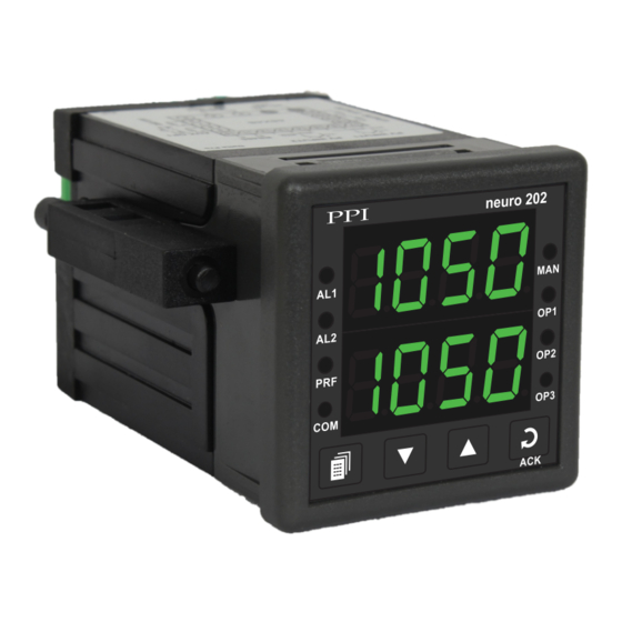
202 User Manual Section 1 FRONT PANEL LAYOUT The controller front panel comprises of digital readouts, LED indicators and membrane keys as shown in Figure 1.1 below. Figure 1.1 neuro 202 Upper Readout Alarm-1 Status Indicator Auto/Manual Status Indicator... - Page 4 202 User Manual Indicator Status • Glows if the Manual (PID) mode is active. • Remains OFF if Automatic (PID). Standby or Profile mode is active. • Indicate Output-1, Output-2 & Output-3 ON/OFF status, respectively, if the Output type is Relay or SSR.
-
Page 5: Basic Operation
202 User Manual Section 2 BASIC OPERATION POWER-UP Upon power-up the controller executes the following sequence of operations. Checks for Sensor Fault. If the connected sensor type is RTD Pt100 and the selected sensor type is any of thermocouples ·... - Page 6 202 User Manual The Lower Readout also facilitates viewing the information about the current profile segment viz.; the Segment Number, Segment Type (ramp / soak) and the Target Set-point (if current segment is ramp) or the Balance Time (if current segment is soak).
- Page 7 202 User Manual MANUAL MODE OPERATION This operation mode is available only if the control action is PID and if the manual mode operation is permitted at supervisory level. In this mode, the controller operates in Open Loop mode wherein the % Output Power is manually adjusted by the operator.
- Page 8 202 User Manual Accessing Operator Page & Adjusting Parameters Step through the following sequence to open the operator page and to adjust the operator parameter values. 1. Press and release PAGE key. The Lower Readout shows (PAGE) and Upper Readout shows (0).
- Page 9 202 User Manual Parameter Description Settings ALARM-2 SETPOINT ALARM-2 DEVIATION BAND Same as that for Alarm-1 above but applied to Alarm-2. ALARM-2 WINDOW BAND Same as that described for Alarm-1 above but applied to Alarm-2.
-
Page 10: Set-Up Mode : Access And Operation
202 User Manual Section 3 SET-UP MODE : ACCESS AND OPERATION The various parameters are arranged in different groups, called PAGES, depending upon the functions they represent. Each group is assigned a unique numeric value, called PAGE NUMBER, for its access. - Page 11 202 User Manual MASTER LOCKING The controller facilitates locking all the PAGES (except Operator PAGE) by applying Master Lock Code. Under Locking, the parameters are available for view only and cannot be adjusted. The Master Lock, however, does not lock the operator parameters.
-
Page 12: Page-10 : Control Parameters
202 User Manual Section 4 PAGE-10 : CONTROL PARAMETERS Refer Table 4.1 for the parameter descriptions and settings. Table 4.1 Settings Parameter Description (Default Value) PROPORTIONAL BAND 1 to 9999 counts (Available for PID Control only) (Default : 500) Sets proportional gain (% power per unit error). - Page 13 202 User Manual Settings Parameter Description (Default Value) PULSE-ON TIME 0.1 to Value set (Available for Pulsed On-Off Control only) for Pulse Time Sets the ON pulse time in seconds for Output-1 Relay / SSR (Default : 1.0) output.
-
Page 14: Page-11 : Alarm Retransmission (Recorder) Parameters
202 User Manual Section 5 PAGE 11 : ALARM AND RETRANSMISSION (RECORDER) PARAMETERS Refer Table 5.1 for parameter description & settings. Table 5.1 Settings Parameter Description (Default Value) ALARM-1 TYPE None Process Low Selects the Alarm-1 activation type. Selecting ‘None’ disables the alarm and suppresses all the related parameters for Alarm-1. - Page 15 202 User Manual Settings Parameter Description (Default Value) ALARM-2 TYPE ALARM-2 SETPOINT ALARM-2 DEVIATION BAND Same as that for Alarm-1 above but ALARM-2 WINDOW BAND applied to Alarm-2. ALARM-2 HYSTERESIS ALARM-2 INHIBIT Same as that described for Alarm-1 above but applied to Alarm-2.
-
Page 16: Page-12 : Input/Output Configuration Parameters
202 User Manual Section 6 PAGE-12 : INPUT/OUTPUT CONFIGURATION PARAMETERS Refer Table 6.1 for parameter description & settings. Table 6.1 Settings Parameter Description (Default Value) CONTROL ACTION On-Off Select appropriate Control Algorithm suited for process Pulse requirement. (Default : PID) - Page 17 202 User Manual Settings Parameter Description (Default Value) Input Type Settings Default SIGNAL HIGH Signal Low to 20.00 0 to 20 mA 20.00 (Available for DC linear mV/V/mA Inputs only) Signal Low to 20.00 4 to 20 mA 20.00 The transmitter output signal value corresponding to PV RANGE Signal Low to 80.00...
- Page 18 202 User Manual Table 6.2 Option Range (Min. to Max.) What it means Resolution Type J Thermocouple 0 to +960°C / +32 to +1760°F Type K Thermocouple -200 to +1376°C / -328 to +2508°F Type T Thermocouple -200 to +385°C / -328 to +725°F Type R Thermocouple 0 to +1770°C / +32 to +3218°F...
-
Page 19: Page-13 : Supervisory Parameters
202 User Manual Section 7 PAGE-13 : SUPERVISORY PARAMETERS Refer Table 7.1 for parameter description & settings. Table 7.1 Settings Parameter Description (Default Value) SELF-TUNE COMMAND (Available for PID control only) Set to ‘Yes’ to initiate a new tuning cycle or set to ‘No’ to abort a (Default : No) tuning operation in progress. - Page 20 202 User Manual Settings Parameter Description (Default Value) PROFILE ABORT COMMAND Disable ON PAGE-1 Enable Supervisory control over availability of Profile Abort command on Page-1. ‘Enable’ for availability. (Default : Disable) CONTROLLER ID NUMBER 1 to 127 Unique numeric code assigned to the controller for identification (Default : 1) by the host.
-
Page 21: Page-16, Page-14, Page-1 : Profile Parameters
202 User Manual Section 8 PAGE-16, PAGE-14, PAGE-1 : PROFILE PARAMETERS Note : This Section is applicable only if the Controller is supplied with “Setpoint Profile” option. The profile utility requires profile configuration and profile settings. Also, the controller facilitates on-line alterations of the parameters pertaining to the running segment. - Page 22 202 User Manual Profile Settings : PAGE-14 Note : The parameters on this page are available only if the profile feature is enabled on Page-16. Use this list of parameters to set individual profile segment for the target setpoint, time interval, holdback type and value. Refer Table 8.2 below.
- Page 23 202 User Manual Table 8.3 Settings Parameter Description (Default Value) END OF PROFILE ACKNOWLEDGE This parameter is available if Output-2 and / or Output-3 Relay / SSR is programmed to turn ON as an ‘End Of Profile’ signal. Set this parameter to ‘Yes’...
- Page 24 202 User Manual Parameter Description Settings SEGMENT BAND VALUE For DC mA/mV/V : 1 to 9999 counts For Thermocouples/RTD : The modified Holdback Band Value is applied immediately on the 1 to 999 or 0.1 to 999.9 current segment.
-
Page 25: Page-15 : Op1, Op2 & Op3 Function Parameters
202 User Manual Section 9 PAGE-15 : OP1, OP2 & OP3 FUNCTION PARAMETERS Refer Table 9.1 for parameter description & settings. Table 9.1 Settings Parameter Description (Default Value) OUTPUT-1 TYPE Relay Select the type in accordance with the hardware configuration for Output-1 (OP1). - Page 26 202 User Manual Settings Parameter Description (Default Value) OP2 EVENT TIME UNITS Seconds (Available if Output-2 function is End of Profile & Event Status is Minutes set to ‘ON’) Hours Select time units for the parameter ‘Output-2 Event Time’.
- Page 27 202 User Manual Settings Parameter Description (Default Value) 0 to 20mA RECORDER OUTPUT TYPE 4 to 20mA (Available if Output-3 function is Recorder) 0 to 5V Select type for Output-3 in accordance with the hardware module fitted. 0 to 10V...
-
Page 28: Mechanical Installation
202 User Manual Section 10 MECHANICAL INSTALLATION OUTER DIMENSIONS AND PANEL CUTOUT The Figure 10.1 shows the controller outer dimensions. Figure 10.1 48mm 94mm (1.89in) (3.70in) neuro 202 7mm (0.276in) Front View Side View PANEL CUTOUT The Figure 10.2 shows the panel cutout requirements for a single controller. - Page 29 202 User Manual PANEL MOUNTING Follow the steps below for mounting the controller on panel: 1. Prepare a square cutout to the size shown in Figure 10.2. 2. Remove the Panel Mounting Clamp from the controller Enclosure and insert the rear of the controller housing through the panel cutout from the front of the mounting panel.
-
Page 30: Electrical Connections
202 User Manual Section 11 ELECTRICAL CONNECTIONS WARNING MISHANDLING / NEGLIGENCE CAN RESULT IN PERSONAL DEATH OR SERIOUS INJURY. 1. The user must rigidly observe the Local Electrical Regulations. 2. Do not make any connections to the unused terminals for making a tie-point for other wires (or for any other reasons) as they may have some internal connections. - Page 31 202 User Manual DESCRIPTIONS The back panel connections are described as under: PV INPUT : RTD Pt100, 3-wire / Thermocouple / mA / mV / V (Terminals : 17, 16, 15) Figure 11.2 (a) Figure 11.2 (b) Figure 11.2 (c)
- Page 32 202 User Manual mA / V Output The Positive (+) of mA / V is available at Terminal 14 & the Negative (-) at Terminal 13. Relay Output Potential-free Relay changeover contacts NO (Normally Open) and C (Common) rated 10A/240 VAC (resistive load).
- Page 33 202 User Manual 85~264 VAC : Power Supply (Terminals 1, 2) The controller is supplied with power connections suited for 85 to 264 VAC line supply. Use well-insulated copper conductor wire of the size not smaller than 0.5mm for power supply connections. Connect Line (Phase) supply line to terminal 1 and the Neutral (Return) supply line to terminal 2 as shown in Figure 11.5 below.
-
Page 34: Appendix-A : Dc Linear Signal Interface
(mV/V/mA) and range. Most PPI instruments, thus, provide programmable Signal Type and Range to facilitate interface with a variety of transmitters. A few industry standard signal types and ranges offered by the PPI instruments are: 0-50mV, 0-200mV, 0-5 V, 1-5 V, 0-10V, 0-20 mA, 4-20 mA, etc. - Page 35 202 User Manual The following examples illustrate appropriate parameter value selections. Example 1: Pressure Transmitter producing 4 to 20 mA 0 to 5 psi Y (psi) Presume the pressure is to be measured Range High 5.00 with 0.01 Resolution, that is 0.00 to 5.00 psi.
- Page 36 202 User Manual Process Precision Instruments 101, Diamond Industrial Estate, Navghar, Vasai Road (E), Dist. Palghar - 401 210.Maharashtra, India Sales : 8208199048 / 8208141446 Support : 07498799226 / 08767395333 sales@ppiindia.net, support@ppiindia.net w w w . p p i i n d i a . n e t...
Need help?
Do you have a question about the neuro 202 and is the answer not in the manual?
Questions and answers