Table of Contents
Advertisement
Advertisement
Table of Contents

Related Manuals for PPI Neuro 102EX


Summary of Contents for PPI Neuro 102EX
- Page 1 Neuro 102EX Enhanced Universal Process Controller User Manual...
-
Page 2: Table Of Contents
102EX User Manual CONTENTS FRONT PANEL LAYOUT BASIC OPERATION SET-UP MODE ACCESS AND OPERATION CONTROL PARAMETERS ALARM PARAMETERS CONFIGURATION PARAMETERS SUPERVISORY PARAMETERS PROFILE PARAMETERS OP2 & OP3 FUNCTION PARAMETERS USER LINEARISATION PARAMETERS HARDWARE ASSEMBLY & CONFIGURATIONS 12. MECHANICAL INSTALLATION 13. -
Page 3: Front Panel Layout
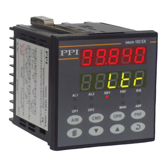
102EX User Manual Section 1 FRONT PANEL LAYOUT The controller front panel comprises of digital readouts, LED indicators and membrane keys as shown in Figure 1.1 below. Figure 1.1 neuro 102 EX Upper Readout Lower Readout Profile Status Alarm-2 Status... - Page 4 102EX User Manual KEYS There are eight tactile keys provided on the front panel for configuring the controller, setting-up the parameter values and selecting Operation / Display Modes. Refer Table 1.2 below. Table 1.2 Symbol Function Press to enter or exit set-up mode.
-
Page 5: Basic Operation
102EX User Manual Section 2 BASIC OPERATION POWER-UP Upon power-up, all displays and indicators are lit on for approximately 3 seconds. This is followed by the indication of the controller model name on the Upper Readout and the firmware version on the Lower Readout, for approx. - Page 6 102EX User Manual PV Error Indications The PV Error type is flashed on the Upper Readout. For different errors and the causes, refer Table 2.1 below. Table 2.1 Message Error Type Cause Over-range PV above Max. Range Under-range PV below Min. Range...
- Page 7 102EX User Manual If enabled at supervisory level, the standby mode can be activated or de-activated by setting the parameter ‘Standby’ to ‘Yes’ or ‘No’ respectively. The standby parameter can be accessed using the front panel ‘CMD’ key, explained later in this section.
- Page 8 102EX User Manual Settings Parameter Description (Default Value) AUXILIARY CONTROL SETPOINT Setpoint Low Limit to The alternate control setpoint that the controller respects for Setpoint High Limit control purpose when selected through remote input terminals. (Default : -200.0) This parameter is available only if the parameter Auxiliary Setpoint is enabled.
- Page 9 102EX User Manual Note: The Command Parameters can also be accessed through PAGE-2. (The pages and parameters are explained in next section). The command parameters are described in Table 2.3. Note that the commands available to the Operator depends upon the feature selected and supervisory permission.
-
Page 10: Set-Up Mode Access And Operation
102EX User Manual Section 3 SET-UP MODE : ACCESS AND OPERATION The various parameters are arranged in different groups, called PAGES, depending upon the functions they represent. Each group is assigned a unique numeric value, called PAGE NUMBER, for its access. - Page 11 102EX User Manual MASTER LOCKING The controller facilitates locking all the PAGES (except Operator PAGE) by applying Master Lock Code. Under Locking, the parameters are available for view only and cannot be adjusted. The Master Lock, however, does not lock the operator parameters.
-
Page 12: Control Parameters
102EX User Manual Section 4 CONTROL PARAMETERS Visit www.ppiindia.net for technical notes on CONTROL and TUNING for detailed understanding of the parameters / terminologies used for describing control parameters in this section. The parameters presented on PAGE-10 depend upon the type of algorithm selected for the control purpose, viz., On-Off, Pulsed On-Off and PID. - Page 13 102EX User Manual Settings Parameter Description (Default Value) (PULSE) ON TIME 0.1 to Value set for Pulse Time (Available for Pulsed On-Off Control only) (Default : 1.0) Sets the ON pulse time in seconds for Relay/SSR output for OP1.
-
Page 14: Alarm Parameters
102EX User Manual Section 5 ALARM PARAMETERS Visit www.ppiindia.net for technical notes on ALARM for detailed understanding of the parameters / terminologies used for describing the Alarm parameters in this section. The parameters required for configuring Alarm-1 and Alarm-2 are grouped on PAGE-11. The configuration includes selecting the type of Alarm, setting the hysteresis value, enabling / disabling start-up Alarm suppression, etc. - Page 15 102EX User Manual Settings Parameter Description (Default Value) ALARM-2 TYPE None Select the Alarm-2 activation type. Selecting ‘None’ will disable Process Low the alarm and suppress all the related parameters for Alarm-2. Process High Deviation Band Window Band (Default : None) Min.
-
Page 16: Configuration Parameters
102EX User Manual Section 6 CONFIGURATION PARAMETERS The controller is provided with a variety of hardware options and software features to cater to a host of applications. The controller thus needs to be appropriately configured in terms of inputs / outputs and other features like control algorithm, digital filter etc. - Page 17 102EX User Manual Settings Parameter Description (Default Value) PV RANGE LOW -19999 to (Available for DC Linear Inputs) PV Range High Sets process value corresponding to minimum DC Linear signal (Default : 0.0) input (e.g., 0V, 0mA, 4mA, etc.)
- Page 18 102EX User Manual Table 6.2 Option Range (Min. to Max. ) Resolution What it means Type J Thermocouple 0.0 to +960°C / +32.0 0 to +1760.0°F Type K Thermocouple -200.0 to +1376.0°C / -328.0 to +2508.0°F Type T Thermocouple -200.0 to +385.0°C / -328.0 to +725.0°F...
-
Page 19: Supervisory Parameters
102EX User Manual Section 7 SUPERVISORY PARAMETERS The supervisory level responsibilities include exercising control over operator, making process related decisions and controlling the availability of process data for remote use. The PAGE-13 parameters allow implementation of supervisory level decisions. The Table 7.1 below list supervisory parameters. - Page 20 102EX User Manual Settings Parameter Description (Default Value) MANUAL MODE Disable Supervisory permission for Manual mode operation. Set to Enable ‘Enable’ for permission. (Default : Disable) ALARM SP ADJUSTMENT Disable ON OPERATOR PAGE Enable Supervisory permission for Alarm setpoint adjustments on Operator Page.
-
Page 21: Profile Parameters
102EX User Manual Section 8 PROFILE PARAMETERS Visit www.ppiindia.net. Refer technical notes on PROFILE for detailed understanding of the parameters / terminologies used for describing the profile parameters in this section. The profile utility requires profile configuration and profile settings. Also, the utility facilitates viewing the various status related information and allows on-line alterations of the operation parameters. - Page 22 102EX User Manual Settings Parameter Description (Default Value) COMMON HOLDBACK The profile allows either Common or Independent Holdback type and value for each of the profile segments. Set this parameter to ‘Yes’ if common settings are desired for the Holdback feature.
- Page 23 102EX User Manual Table 8.3 PAGE 1 (‘CMD’ Key) Profile Status Information Lower Readout Upper Readout Prompt Information ACTIVE SEGMENT NUMBER The current profile segment (ramp / soak) is in progress, 1 to 16. SEGMENT TYPE The current segment is Ramp.
- Page 24 102EX User Manual Section 9 OP2, OP3, OP4 & OP5 PARAMETERS The controller is supplied with four optional hardware plug-in modules, viz., OP2,OP3, OP4 & OP5 The OP2 module is factory configured for either Relay / SSR (jumper selectable) or DC Linear Voltage or DC Linear Current. It can be programmed to function as Event Output for End-of-Profile or Cool Control Output for Bi-directional Control.
- Page 25 102EX User Manual Settings Parameter Description (Default Value) OP2 EVENT TIME UNITS Seconds (Available if OP2 function is End of Profile) Minutes Select time units for the parameter ‘OP2 Event Time’. Hours (Default : Seconds) None OUTPUT-3 FUNCTION SELECTION...
- Page 26 102EX User Manual Settings Parameter Description (Default Value) 0 - 20 mA RECORDER OUTPUT TYPE 4 - 20 mA (Available if OP3 function is recorder) Select type for Output-3 (OP3) in accordance with the hardware 0 - 5 Volts module fitted.
-
Page 27: User Linearisation Parameters
102EX User Manual Section 10 USER LINEARISATION PARAMETERS Visit www.ppiindia.net for technical notes on USER LINEARISATION for detailed understanding of the parameters / terminologies used for describing the parameters in this section. The parameters listed on this page are used to implement the linearisation curve on the process value represented by the DC linear output of a transmitter. -
Page 28: Hardware Assembly & Configurations
102EX User Manual Section 11 HARDWARE ASSEMBLY AND CONFIGURATIONS Figure 11.1 Ventilations Panel Mounting Clamp Bezel Rear Terminals Enclosure Front Label Pullout Latch Connection Diagram The Figure 11.1 above shows the controller outer-case viewed with front label upright. ELECTRONIC ASSEMBLY The basic electronics assembly (without any plug-in modules), comprises of 4 Printed Circuit Boards (PCB). - Page 29 102EX User Manual Removing Assembly from Enclosure Hold the controller upside down and press the pullout latch to unlock the front bezel from the enclosure (Refer Figure 11.2). Pull the bezel outward. The electronics assembly comes out with the bezel.
- Page 30 102EX User Manual OUTPUT-1 : Jumper Settings The Output-1 Type is user selectable as Relay, SSR, DC Volts or DC Current. Besides the parameter settings, the Output-1 configuration requires proper jumper settings. The jumper settings are provided as Pins & Shorting Link arrangement (marked ‘B’...
- Page 31 102EX User Manual Figure 11.5(b) 10-Pin Male Plugs Output PCB Top View CPU PCB Bottom View Push the modules towards front for mounting and pull the modules towards back for removal. (a) Relay / SSR Module The Relay/SSR Module is supported by OP2, OP3 & OP4.The module can be configured to function as either Relay or SSR output by appropriate jumper settings ‘A’...
- Page 32 102EX User Manual Serial Communication Plug-in Module The 8-Pin miniature Male Plug for mounting the Serial Communication Module is located on the CPU PCB, as shown in the Figure 11.8 below. The Serial Communication Module is provided with a 8-Pin miniature female sockets on the bottom side for the mounting purpose.
-
Page 33: Mechanical Installation
102EX User Manual Section 12 MECHANICAL INSTALLATION The following precautions should be strictly observed while installing the controller: 1. The place of installation should be free of corrosive/combustible gases and electrically conductive pollution. 2. Ensure that the place of installation is not subject to rapid ambient changes that can cause condensation. Also the Ambient Temperature and Relative Humidity surrounding the controller should not exceed the maximum specified for the proper operation of the controller. - Page 34 102EX User Manual Figure 12.2 Panel Cutout 91 X 91 mm -0, +0.5 mm (3.55 X 3.55 in) (-0, +0.02 in) 10mm (0.39in) Figure 12.3 Panel Mounting Clamp Tighten the screw Mounting Panel with Square Cutout Metallic Projection...
-
Page 35: Electrical Connections
102EX User Manual Section 13 ELECTRICAL CONNECTIONS WARNING M I S H A N D L I N G / N E G L I G E N C E C A N RESULT IN PERSONAL DEATH OR SERIOUS INJURY. - Page 36 102EX User Manual DESCRIPTIONS The back panel connections are described as under: INPUT (Terminals : 1, 2, 3) The controller accepts Thermocouples (J, K, T, R, S, B, N), 3-wire RTD Pt100 and DC Linear Current/Voltage (mV/V/mA) as input.
- Page 37 102EX User Manual Figure 13.3 (c) DC Linear Current / Voltage Output The DC Linear (0/4-20 mA) Current or (0-5/10V) Voltage output is also available at Terminal 21 (+) and Terminal 22 (-) if the Output-1 is configured for DC Linear.
- Page 38 102EX User Manual If the Optional plug-in communication board is fitted, connect terminal 7 and 8 of the controller to (+) and (-) terminals of the Master device. For reliable noise free communication, use a pair of twisted wires inside screened cable as shown in Figure 13.5. The wire should have less than 100 ohms / km nominal DC resistance (Typically 24 AWG or thicker).
- Page 39 102EX User Manual APPENDIX-A MODBUS COMMUNICATION ADDRESSES Notes : 1. Protocol implemented : Modbus RTU over Serial. 2. All controller parameters/variables are implemented using INPUT or HOLDING Registers. DISCRETE INPUT and COILS not implemented. 3. Both Input and Holding registers are assigned unique Modbus Addresses, starting from 1.
- Page 40 102EX User Manual PARAMETER SETTINGS Reg. Address Reg. Type Input 1 : On 0 : Off Alarm-2 Status Input -20.0°C to 80.0°C Ambient Temperature in °C Integer value to be interpreted with fixed 0.1 resolution. e.g. Interpret 300°C as 30.0°C.
- Page 41 102EX User Manual PARAMETER SETTINGS Reg. Address Reg. Type Input 1 : Write is Permitted 0 : Write not Permitted Profile Hold Status Input 1 : Write is Permitted 0 : Write not Permitted Serial Write Permission Input 16 to 24...
- Page 42 102EX User Manual PARAMETER SETTINGS Reg. Address Reg. Type Read Operation Holding 1 : Tuning 0 : Not Tuning Write Operation Self-Tune Command 129 : Start Tuning 128 : Abort Tuning Other Values : Don't Care Holding Resolution Based Parameter Min.
- Page 43 102EX User Manual PARAMETER SETTINGS Reg. Address Reg. Type 0 : None Holding 1 : Process Low 2 : Process High Alarm1 Type for Analog Channel 3 : Deviation Band 4 : Window Band Holding Resolution Based Parameter Alarm1 Hysteresis for Analog Channel...
- Page 44 102EX User Manual PARAMETER SETTINGS Reg. Address Reg. Type Holding 0 : Relay 1 : SSR 2 : 0-20mA 3 : 4-20mA 4 : 0-5V 5 : 0-10V OP2 (Cool) Type Holding Resolution Based Parameter Min. PV Range to...
- Page 45 102EX User Manual PARAMETER SETTINGS Reg. Address Reg. Type Holding 0 to 3600 Seconds Integral Time Holding 0 to 600 Seconds Derivative Time Holding Fixed 0.1 resolution 0.1 to 10.0 Relative Cool Gain Holding Fixed 0.1% resolution 0.0% to Heat Power High...
- Page 46 102EX User Manual PARAMETER SETTINGS Reg. Address Reg. Type Holding 1 : Enable Manual Control Enable 0 : Disable Holding Fixed 0.1% Resolution -100.0% to 100.0% Manual PID Power Holding 1 : Enable 0 : Disable Standby Mode Enable...
- Page 47 102EX User Manual PARAMETER SETTINGS Reg. Address Reg. Type Holding Read Operation Returns 0 End Of Profile Acknowledge Write Operation 1 : Acknowledged 0 : Don't Care 98, to 161 Holding Profile Segment Parameters (Class Segment) Min. to Max. Range ·...
- Page 48 102EX User Manual PARAMETER SETTINGS Reg. Address Reg. Type Holding 0 : Process Value 1 : Setpoint Retransmission base PV / SP 0 : 0 - 20mA Holding 1 : 4 - 20mA 2 : 0 - 5V Retrans Output Type...
- Page 49 102EX User Manual PARAMETER SETTINGS Reg. Address Reg. Type Holding 1 : Enable 0 : Disable Master Lock Holding 184 to 200 1 to 32 Reserve Write/Read Holding -1999 to 9999 User Linearization Enable / Disable Holding -1999 to 9999...
- Page 50 102EX User Manual PARAMETER SETTINGS Reg. Address Reg. Type Holding -1999 to 9999 End Calibration Holding -1999 to 9999 Factory Cal Yes / No Holding -1999 to 9999 Factory Write Holding 1 : Enable 0 : Disable Extended Table ( Demark )
- Page 51 Process Precision Instruments 101, Diamond Industrial Estate, Navghar, Vasai Road (E), Dist. Palghar - 401 210.Maharashtra, India 0250 - 2391722/33/37/42 07498799226, 09321985369 sales@ppiindia.net, support@ppiindia.net w w w . p p i i n d i a . n e t...
Need help?
Do you have a question about the Neuro 102EX and is the answer not in the manual?
Questions and answers