Advertisement
Table of Contents
- 1 Table of Contents
- 2 Front Panel Layout
- 3 Basic Operation
- 4 Set-Up Mode Access and Operation
- 5 Control Parameters
- 6 Alarm Parameters
- 7 Configuration Parameters
- 8 Supervisory Parameters
- 9 Profile Parameters
- 10 Op2 & Op3 Function Parameters
- 11 Hardware Assembly & Configurations
- 12 Mechanical Installation
- 13 Electrical Connections
- 14 Front Panel Layout
- 15 Back Panel Terminal Connections
- 16 Input & Output Hardware Jumper Settings
- Download this manual
Advertisement
Table of Contents

Related Manuals for PPI Epsilon 48


Summary of Contents for PPI Epsilon 48
- Page 1 EPSILON Self Tune PID Process Controller with Ramp / Soak Profile P R F User Manual...
-
Page 2: Table Of Contents
EPSILON User Manual CONTENTS For Size 48X48 1. FRONT PANEL LAYOUT 2. BASIC OPERATION SET-UP MODE ACCESS AND OPERATION CONTROL PARAMETERS ALARM PARAMETERS CONFIGURATION PARAMETERS SUPERVISORY PARAMETERS PROFILE PARAMETERS OP2 & OP3 FUNCTION PARAMETERS HARDWARE ASSEMBLY & CONFIGURATIONS MECHANICAL INSTALLATION 12. -
Page 3: Front Panel Layout
EPSILON User Manual Section 1 FRONT PANEL LAYOUT The controller front panel comprises of digital readouts, LED indicators and membrane keys as shown in Figure 1.1 below. Figure 1.1 EPSILON Upper Readout Lower Readout Alarm-1 Status Alarm-2 Status Output-2 Status Profile Status Output-1 Status PAGE Key... - Page 4 EPSILON User Manual Table 1.2 Symbol Function Press to enter or exit set-up mode. PAGE Press to decrease the parameter value. Pressing once decreases DOWN the value by one count; keeping pressed speeds up the change. Press to increase the parameter value. Pressing once increases the value by one count;...
-
Page 5: Basic Operation
EPSILON User Manual Section 2 BASIC OPERATION POWER-UP Upon power-up, all displays and indicators are lit on for approximately 3 seconds. This is followed by the indication of the controller model name on the Upper Readout and the firmware version on the Lower Readout, for approximately 1 second. - Page 6 EPSILON User Manual CONTROL / ALARM STATUS UNDER PV ERROR CONDITIONS a) The tuning, if in progress, is aborted. b) The Profile Cycle, if in progress, enters in HOLD state. c) Under Over-range or Under-range error condition, all the control outputs are switched off. However, under Sensor Open error, the PID control output power is maintained at the value set for the parameter “Sensor Break Output Power”...
- Page 7 EPSILON User Manual Table 2.2 Settings Parameter Description (Default Value) END OF PROFILE ACKNOWLEDGE This parameter is available if Output-2 (OP2) and / or Output-3 (OP3) Relay/SSR is programmed to turn ON as an ‘End-of-Profile’ signal. Set this parameter to ‘Yes’ (after end of profile is reached) (Default : No) to acknowledge the Alarm and to turn OFF the output.
- Page 8 EPSILON User Manual Settings Parameter Description (Default Value) Throughout the range for ALARM-1 SETPOINT the selected Input Type The setpoint / Band value (depending upon the type of Alarm) for (Default : Alarm-1. This parameter is not available if the selected Alarm type For Process Low : -199 is ‘None’.
-
Page 9: Set-Up Mode Access And Operation
EPSILON User Manual Section 3 SET-UP MODE : ACCESS AND OPERATION The various parameters are arranged in different groups, called PAGES, depending upon the functions they represent. Each group is assigned a unique numeric value, called PAGE NUMBER, for its access. The parameters are always presented in a fixed format: The Lower Readout displays the parameter prompt (Identification Name) and the Upper Readout displays the set value. - Page 10 EPSILON User Manual MASTER LOCKING The controller facilitates locking all the PAGES (except Operator PAGE) by applying Master Lock Code. Under Locking, the parameters are available for view only and can not be adjusted. The Master Lock, however, does not lock the operator parameters.
-
Page 11: Control Parameters
EPSILON User Manual Section 4 CONTROL PARAMETERS Visit www.ppiindia.net. Refer technical notes on CONTROL and TUNING for detailed understanding of the parameters / terminologies used for describing control parameters in this section. The parameters presented on PAGE-10 depend upon the type of algorithm selected for the control purpose, viz., On-Off, Pulsed On-Off and PID. - Page 12 EPSILON User Manual Settings Parameter Description (Default Value) 0.1 to Value set ON TIME for Pulse Time (Available for Pulsed On-Off Control only) (Default : 1.0) Sets the ON pulse time in Seconds for Relay/SSR Output for OP1. *COOL HYSTERESIS 1 to 999 (Available for On-Off or Pulsed On-Off Control with bi-directional mode) (Default : 2)
-
Page 13: Alarm Parameters
EPSILON User Manual Section 5 ALARM PARAMETERS Visit www.ppiindia.net. Refer technical notes on ALARM for detailed understanding of the parameters/terminologies used for describing the Alarm parameters in this section. The parameters required for configuring Alarm-1 and Alarm-2 are grouped on PAGE-11. The configuration includes selecting the type of Alarm, setting the hysteresis value, enabling / disabling start-up alarm suppression, etc. - Page 14 EPSILON User Manual Settings Parameter Description (Default Value) Min. to Max. Range specified ALARM-2 SETPOINT for the selected Input Type (Available for Process High or Process Low Alarm-2 Type) (Default : Min or Max Range) Sets Alarm limit independent of control setpoint for Alarm-2. ALARM-2 DEVIATION BAND -999 to 999 (Available for Deviation Band Alarm-2 Type)
-
Page 15: Configuration Parameters
EPSILON User Manual Section 6 CONFIGURATION PARAMETERS The controller is provided with a variety of hardware options and software features to cater to a host of applications. The controller thus needs to be appropriately configured in terms of inputs / outputs and other features like control algorithm, digital filter, etc. - Page 16 EPSILON User Manual Settings Parameter Description (Default Value) PV RANGE HIGH -1999 to 9999 ( Available for DC Linear Inputs) (Default : 1000) Sets process value corresponding to maximum DC Linear signal input (e.g., 5 V, 10 V, 20 mA, etc.) Min.
- Page 17 EPSILON User Manual Table 6.2 Option What it means Range (Min. to Max. ) Resolution Type J Thermocouple 0 to +960°C / +32 to +1760°F Type K Thermocouple -200 to +1376°C / -328 to +2508°F Type T Thermocouple -200 to +385°C / -328 to +725°F Type R Thermocouple 0 to +1770°C / +32 to +3218°F Fixed...
-
Page 18: Supervisory Parameters
EPSILON User Manual Section 7 SUPERVISORY PARAMETERS The supervisory level responsibilities include exercising control over operator, making process related decisions and controlling the availability of process data for remote use. The PAGE-13 parameters allow implementation of supervisory level decisions. The Table 7.1 below list supervisory parameters. Table 7.1 Settings Parameter Description... - Page 19 EPSILON User Manual Settings Parameter Description (Default Value) UTILITY OPTION SELECTION None Enable / Disable the available utility feature. Set to ‘None’ for Serial Comm. disabling utility feature. Auxiliary Setpoint (Default : Serial Comm.) 4800 BAUD RATE Communication speed in ‘Bits per Second’. Set the value to match 9600 with the host baud rate.
-
Page 20: Profile Parameters
EPSILON User Manual Section 8 PROFILE PARAMETERS Visit www.ppiindia.net. Refer technical notes on PROFILE for detailed understanding of the parameters/ terminologies used for describing the profile parameters in this section. The profile utility requires profile configuration and profile settings. Also, the utility facilitates viewing the various status related information and allows on-line alterations of the operation parameters. - Page 21 EPSILON User Manual Settings Parameter Description (Default Value) OUTPUT OFF Set to ‘Yes’ if after the end of profile, all the control outputs are to be forced Off till the issuance of next profile Start command. (Default : No) ‘POWER FAIL RECOVERY’ STRATEGY Abort A running profile shall terminate in case of power failure.
- Page 22 EPSILON User Manual Table 8.3 Lower Readout Upper Readout Prompt Information Profile Status Information : PAGE 1 Active Segment Number The current profile segment (ramp / soak) number in progress. Segment Type The current segment is Ramp. The current segment is Soak. Target Setpoint Target setpoint value for the current segment.
-
Page 23: Op2 & Op3 Function Parameters
EPSILON User Manual Section 9 OP2 & OP3 FUNCTION PARAMETERS The controller is supplied with two optional hardware plug-in modules, viz., OP2 and OP3. The modules are interchangeable and factory configured for either Relay / SSR (jumper selectable) or DC Linear Voltage or DC Linear Current. The OP2 module can be programmed to function as an Output for any one of the followings : Alarm-1, End of Profile, Cool Control for Bi-directional Control, Auxiliary Control or Blower Control. - Page 24 EPSILON User Manual Settings Parameter Description (Default Value) OP2 EVENT TIME (Available if OP2 function is End of Profile & if OP2 Event Status set to 0 to 9999 (Default : 0) Set the time (in selected units) for which the OP2 is to be kept ON after the End of Profile.
- Page 25 EPSILON User Manual Settings Parameter Description (Default Value) None OUTPUT-3 FUNCTION SELECTION Alarm (Applicable for OP3 hardware module, if fitted) Select the function / feature to which the OP3 module is to be End Of Profile logically attached for activation. Recorder (Default : Alarm) ALARM-2 LOGIC...
- Page 26 EPSILON User Manual Settings Parameter Description (Default Value) RECORDER LOW Min. to Max. Range Specified for the (Available if OP3 function is recorder) Set the minimum parameter value (SP or PV) that shall Selected Input Type correspond to the minimum recorder output signal level (0 mA or 4 (Default : -199) mA or 0 V).
-
Page 27: Hardware Assembly & Configurations
EPSILON User Manual Section 10 HARDWARE ASSEMBLY AND CONFIGURATIONS The Figure 10.1 below shows the controller outer-case viewed with front label upright. Figure 10.1 Ventilations Rear Terminals Panel Mounting Clamp Panel Sealing Gasket N / C Bezel N / O N / O L A Y L in... - Page 28 EPSILON User Manual Removing Assembly from Enclosure With the controller upright, hold the Bezel with the fingers on the pullout grips provided on the left and right sides of the bezel. Pull the bezel outward. The assembly comes out with the bezel. Placing Assembly Back into Enclosure With the controller upright (the UP inscribed on the Enclosure is on the topside), insert the bezel gently with the boards on either side sliding into the guides provided inside of the Enclosure.
- Page 29 EPSILON User Manual Table 10.1 Output-1 Jumper Settings Jumper Setting - B Jumper Setting - C Output Type Relay SSR Drive DC Linear Current (or Voltage) MOUNTING PLUG-IN MODULES The controller supports up to 3 plug-in modules, viz. Output-2 Module (Relay/SSR or DC Linear), Output-3 Module (Relay/SSR or DC Linear) and Option Module (RS485 Serial Port or Digital Input for Auxiliary Setpoint selection).
- Page 30 EPSILON User Manual Table 10.2 Output Type Jumper Setting - A Jumper Setting - B Relay DC Linear Voltage / Current Module The DC Linear Module is factory configured for either Current or Voltage output. The current output can be configured for 0-20 mA or 4-20 mA and similarly the voltage output can be configured for 0-5 V or 0-10 V through parameter settings.
- Page 31 EPSILON User Manual Figure 10.8 Mounting Output-3 Module Plug & Socket Connector Output Module Projected Parts Slots CPU Board Front Label Upside-down The plug for the Serial Communication or Auxiliary SP Selection module is located on the Power-supply PCB. The Figure 10.9 below illustrates how to plug-in the Serial Communication/Auxiliary SP module.
-
Page 32: Mechanical Installation
EPSILON User Manual Section 11 MECHANICAL INSTALLATION The following precautions should be strictly observed while installing the controller: 1. The place of installation should be free of corrosive/combustible gases and electrically conductive pollution. 2. Ensure that the place of installation is not subject to rapid ambient changes that can cause condensation. Also the Ambient Temperature and Relative Humidity surrounding the controller should not exceed the maximum specified for the proper operation of the controller. - Page 33 EPSILON User Manual PANEL MOUNTING Follow the steps below for mounting the controller on panel: 1. Prepare a square cutout to the size shown in Figure 11.2. 2. Remove the Panel Mounting Clamp from the controller Enclosure. 3. Insert the rear of the controller housing through the panel cutout from the front of the mounting panel. Hold the controller gently against the mounting panel such that it positions squarely against the panel wall, see Figure 11.3.
-
Page 34: Electrical Connections
EPSILON User Manual Section 12 ELECTRICAL CONNECTIONS WARNING WARNING M I S H A N D L I N G / N E G L I G E N C E C A N MISHANDLING / NEGLIGENCE CAN RESULT IN PERSONAL DEATH OR SERIOUS RESULT IN PERSONAL DEATH OR INJURY. - Page 35 EPSILON User Manual DESCRIPTIONS The back panel connections are described as under: INPUT (Terminals : 1, 2, 3) The controller accepts Thermocouples (J, K, T, R, S, B, N), 3-wire RTD Pt100 and DC Linear Current/Voltage (mV / V / mA) as input.
- Page 36 EPSILON User Manual Figure 12.3 (c) DC Linear Current / Voltage Output The DC Linear (0/4-20 mA) Current or (0-5/10 V) Voltage output is also available at Terminal 6 (+) and Terminal 4 (-) if the Output-1 is configured for DC Linear. OUTPUT- 2 (Terminals : 7, 8, 9) OUTPUT- 3...
- Page 37 EPSILON User Manual DIGITAL INPUT FOR AUXILIARY SP SELECTION (Terminals : 14, 15) (Applicable if the Option plug-in module for Auxiliary SP Selection is fitted.) Figure 12.6 (a) Figure 12.6 (b) Potential-free TTL-Compatible Contact closure Voltage Level The plug-in Option module for selecting Auxiliary SP is factory configured for either potential-free contact closure or TTL- compatible voltage input.
- Page 38 EPSILON 96X96 User Manual EPSILON 96X96...
-
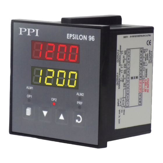
Page 39: Front Panel Layout
EPSILON 96X96 User Manual Section 1 FRONT PANEL LAYOUT Figure 1.1 EPSILON 96 Upper Readout Lower Readout ALM1 ALM2 Alarm-2 Status Alarm-1 Status Profile Status Output-1 Status Output-2 Status ENTER Key PAGE Key DOWN Key UP Key The front panel contains digital readouts, LED indicators and keys. READOUTS The Upper Readout is a 4 digit, 7-segment bright red LED display and usually displays the PV (Process Value). - Page 40 EPSILON 96X96 User Manual KEYS The Table 1.2 lists the four front panel keys and the associated function. Table 1.2 Symbol Function Press to enter or exit set-up mode. PAGE Press to decrease the parameter value. Pressing once decreases DOWN the value by one count;...
-
Page 41: Back Panel Terminal Connections
EPSILON 96X96 User Manual Section 2 BACK PANEL TERMINAL CONNECTIONS Figure 2.1 96 X 96 INPUT (Terminals 1, 2 & 3) The controller accepts Thermocouples (J, K, T, R, S, B, N) or 3-wire RTD Pt100 and DC linear current/Voltage (mV/V/mA) as input. - Page 42 EPSILON 96X96 User Manual OUTPUT-1 (Terminals 4, 5 & 6) The Output-1 can be configured (through jumper settings) as either Relay, SSR Drive or DC Linear output. Note that either Current (mA) or Voltage is provided as DC Linear output. Figure 2.3 (a) Figure 2.3 (b) Figure 2.3 (c )
- Page 43 EPSILON 96X96 User Manual SERIAL COMMUNICATION PORT (Applicable if the Option plug-in module for RS485 Serial Port is fitted.) Figure 2.6 Terminating Resistor Twisted (100 to 150 Ohms) Wire Pair 14 (B-) HOST 15 (B+) Screened Cable Serial Comm. Master Device Terminals Connect terminal 15 and 14 of the controller to the BUS(+) and BUS(-) terminals of the master device.
-
Page 44: Input & Output Hardware Jumper Settings
EPSILON 96X96 User Manual Section 3 INPUT & OUTPUT HARDWARE JUMPER SETTINGS Figure 3.1 Display Output 2 Jumper Setting Output 1 B & C Keys Jumper Settings CPU Board Input Jumper Setting INPUT : Jumper Settings In addition to parameter settings, the Input Type selection also requires proper jumper settings. For the jumper settings; Pins & Shorting-Link arrangement, marked ‘A’, is provided on the CPU PCB as shown in Figure 3.1. - Page 45 EPSILON 96X96 User Manual OUTPUT-1 : Jumper Settings Output-1 Type is user selectable as Relay, SSR, DC Volts or DC Current. Besides the parameter settings, the Output-1 configuration requires proper jumper settings. The jumper setting are provided as Pins & Shorting Link arrangement (marked ‘B’...
- Page 46 EPSILON 96X96 User Manual OUTPUT-3 : Jumper Settings Output-3, if fitted, is jumper selectable as either Relay or SSR using Pins & Shorting Link arrangement (marked ‘A’ & ‘B’) on Power Supply PCB, as shown in Figure 3.2 and listed in Table 3.4 below. Figure 3.2 Output 3 Jumper Setting...
- Page 47 Process Precision Instruments 101, Diamond Industrial Estate, Navghar, Vasai Road (E), Dist. Palghar - 401 210.Maharashtra, India 0250 - 2391722/33/37/42 07498799226, 09321985369 sales@ppiindia.net, support@ppiindia.net w w w . p p i i n d i a . n e t...
Need help?
Do you have a question about the Epsilon 48 and is the answer not in the manual?
Questions and answers