
Related Manuals for BGH BV-V28W/DHN1


Summary of Contents for BGH BV-V28W/DHN1
- Page 1 Service Manual VRF Unidades Exteriores Modelos: BV-V28W/DHN1(At), BV-V36W/DHN1(At), BV-V42W/DHN1(At), BV-V48W/DHN1(At), BV-V56W/DHN1(At).
- Page 2 Contents Part 1 General Informa on ................3 Part 2 Component Layout and Refrigerant Circuits ........7 Part 3 Control ....................18 Part 4 Field Se ngs ..................28 Part 5 Electrical Components and Wiring Diagrams ........33 Part 6 Diagnosis and Troubleshoo ng ............47...
- Page 3 VRF 50/60Hz...
- Page 4 Part 1 1 Indoor and Outdoor Unit Capaci es ............4 2 External Appearance ................4 3 Combina on Ra o .................. 6...
- Page 5 — Notes: Atom series indoor units could connect to Atom series outdoor units. 1.2 Outdoor Units Table 1-1.3: Outdoor unit capacity range Capacity (kBtu/h) Model Name BV-V28W/DHN1(At) BV-V36W/DHN1(At) BV-V42W/DHN1(At) BV-V48W/DHN1(At) BV-V56W/DHN1(At) Notes: Atom series outdoor units could not be combined.
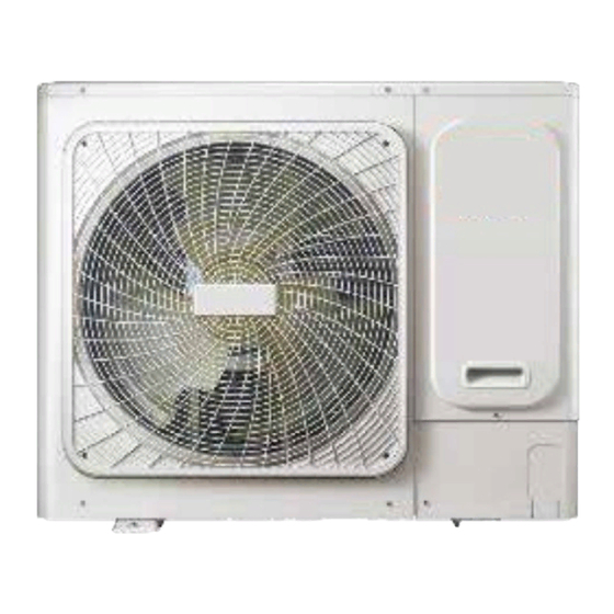
- Page 6 2 External Appearance 2.1 Indoor Units Table 1-2.1: Indoor unit appearance One-way Casse e Four-way Casse e Compact Four-way Casse e Wall-mounted Medium Sta c Pressure Duct 2.2 Outdoor Units Table 1-2.2: Outdoor unit appearance 28 kBtu/h 36/42 kBtu/h 48/56 kBtu/h...
- Page 7 VRF 50/60Hz 3 Combination Ratio Sum of capacity indexes of the indoor units Combination ratio = Capacity index of the outdoor unit Table 1-3.1: Indoor and outdoor unit combination ratio limitations Type Minimum combination ratio Maximum combination ratio Atom Series outdoor units 130% Table 1-3.2: Combinations of Indoor and outdoor units Outdoor unit capacity...
- Page 8 Part 2 Component Layout and Refrigerant Circuits 1 Piping Diagrams ..................8 2 Refrigerant Flow Diagrams ..............10...
- Page 9 VRF 50/60Hz 1 Piping Diagrams Figure 2-1.1: 28 model piping diagram Figure 2-1.2: 36/42 model piping diagram...
- Page 10 Figure 2-1.3: 48/56 model piping diagram Key components: 1. Oil separator: Separates oil from gas refrigerant pumped out of the compressor and quickly returns it to the compressor. Separa on efficiency is up to 99%. 2. Gas-liquid separator: Stores liquid refrigerant and oil to protect compressor from liquid hammering. 3.
- Page 11 VRF 50/60Hz 2 Refrigerant Flow Diagrams Cooling operation Figure 2-2.1:28 model refrigerant flow during cooling operation Figure 2-2.2: 36/42 model refrigerant flow during cooling operation...
- Page 12 Figure 2-2.3: 48/56 model refrigerant flow during cooling opera on Oil return opera on in cooling mode Figure 2-2.4: 28 model refrigerant flow during oil return opera on in cooling mode...
- Page 13 VRF 50/60Hz Figure 2-2.5: 36/42 model refrigerant flow during oil return operation in cooling mode Figure 2-2.6: 48/56 model refrigerant flow during oil return operation in cooling mode...
- Page 14 Hea ng opera on Figure 2-2.7: 28 model refrigerant flow during hea ng opera on Figure 2-2.8: 36/42 model refrigerant flow during hea ng opera on...
- Page 15 VRF 50/60Hz Figure 2-2.9: 48/56 model refrigerant flow during heating operation Oil return operation in heating mode Figure 2-2.10: 28 model refrigerant flow during oil return operation in heating mode...
- Page 16 Figure 2-2.11: 36/42 model refrigerant flow during oil return opera on in hea ng mode Figure 2-2.12: 48/56 model refrigerant flow during oil return opera on in hea ng mode...
- Page 17 VRF 50/60Hz Defrosting operation Figure 2-2.13: 28 model refrigerant ow during defrosting operation Figure 2-2.14: 36/42 model refrigerant ow during defrosting operation...
- Page 18 Figure 2-2.15: 48/56 model refrigeran ow during defrosting operation...
-
Page 19: Table Of Contents
VRF 50/60Hz Part 3 Control 1 General Control Scheme Flowchart ............19 2 Stop Operation ..................20 3 Standby Control ..................20 4 Startup Control ..................21 5 Normal Operation Control ..............22 6 Protection Control................. 23 7 Special Control ..................25... -
Page 20: General Control Scheme Flowchart
1 General Control Scheme Flowchart Sec ons 3-2 to 3-7 on the following pages detail when each of the controls in the flowchart below is ac vated. Stop opera on • Abnormal shutdown • System stop Standby control • Crankcase heater control Thermo on Startup control •... -
Page 21: Stop Operation
VRF 50/60Hz 2 Stop Operation The stop operation occurs for one of the two following reasons: 1. Abnormal shutdown: in order to protect the compressors, if an abnormal state occurs the system makes a 'stop with thermo off' operation and an error code is displayed on the outdoor unit digital displays. 2. -
Page 22: Startup Control
4 Startup Control 4.1 Compressor Startup Delay Control When the ODU is powered on again and the compressor delays about 7 minutes to start. A er the compressor stops running, it takes about 4 minutes to restart, in order to prevent frequent compressor on/off and to equalize the pressure within the refrigerant system. - Page 23 VRF 50/60Hz 5 Normal Opera n Control 5.1 Component Control during Normal Opera on Table 3-5.1: Component control during normal cooling opera on Wiring diagram Component 28-56 model Control func ons and states label • Inverter compressor COMP Controlled according to load requirement Fan speed controlled according to heat exchanger temperature •...
- Page 24 6 Protec on Control 6.1 High Pressure Protec on Control This control protects the system from abnormally high pressure and protects the compressors from transient spikes in pressure. Figure 3-6.1: High pressure protec on control Normal opera on > 4.4MPa <...
-
Page 25: Normal Operation Control
VRF 50/60Hz 6.4 Compressor and Inverter Module Protection Control This control protects the compressors from abnormally high currents and protects the inverter modules from abnormally high temperatures. Figure 3-6.4: Compressor current protection control Normal operation Current ≥ Current Current < Current Compressor current protection, error code P3 is displayed 6.5 Disable Cooling Control When the outdoor ambient temperature drops below or equal to -5°C ,... -
Page 26: Special Control
7 Special Control 7.1 Oil Return Opera on In order to prevent compressors from running out of oil, the oil return opera on is conducted to recover oil that has flowed out of the compressor(s) and into the piping system. This opera on is performed for all units including units that are in standby. - Page 27 VRF 50/60Hz 7.2 Defrosting Operation In order to recover hea ng capacity, the defrosting opera on is conducted when the outdoor unit heat exchanger is performing as an evaporator. The defros ng opera on is controlled according to outdoor ambient temperature, outdoor heat exchanger temperature, indoor heat exchanger temperature and outdoor unit running me.
- Page 28 VRF 50/60Hz Part 4 Field Settings 1 Outdoor Unit Field Settings ..............29...
- Page 29 1 Outdoor Unit Field Settings Figure 4-1.1: 28 model outdoor unit main PCB switches Dial switches Check button Digital display Table 4-1.1: 28 model outdoor unit main PCB switch settings Switch Switch Setting Description positions Spot check button and force cooling button(long pressed over 5 seconds 1.Spot check would into forced cooling mode, long pressed over 5 seconds again would 2.Force cooling...
- Page 30 VRF 50/60Hz Figure 4-1.2: 36/42 model outdoor unit main PCB switches and communication switchboard Communication switchboard Dial switch Digital display Check button Main board Power switch ENC3 switch Table 4-1.2: 36/42 model outdoor unit main PCB switch settings Switch Switch Setting Description positions...
- Page 31 Figure 4-1.3: 48/56 model outdoor unit main PCB switches and communication switchboard Digital display Check button and force cooling button Dial switch ENC2/ENC3 Table 4-1.3: 48/56 model outdoor unit main PCB switch settings Switch Switch Setting Description positions Force Press SW1 to enter the forced cooling function; press it again to exit the forced cooling cooling function Spot...
- Page 32 VRF 50/60Hz Table 4-1.4: Spot check display table (for all model) DSP1 content Parameters displayed on DSP2 Remarks 0.-- Actual value = value displayed Operating frequency 1.-- Operating mode Refer to Note 1 2.-- Operating fan speed level Refer to Note 2 3.-- Total capacity requirement of indoor units 4.--...
- Page 33 Part 5 Electrical Components and Wiring Diagrams 1 Outdoor Unit Electric Control Box Layout ..........34 2 Outdoor Unit Main PCB ................36 3 Wiring Diagrams ..................43...
- Page 34 VRF 50/60Hz 1 Outdoor Unit Electric Control Box Layout Figure 5-1.1: Front view of 28 model electric control box Power input and power filter Module board PFC module IPM module DC fan motor control module Output control assembly Main control board Figure 5-1.2: Front view of 36/42 model electric control box Common mode inductor PFC module...
- Page 35 Figure 5-1.3: Front view of 48/56 model electric control box DC fan control Switch power supply module IPM module Communication terminals PFC module Main control board Power input and Filter board filter assembly Power input terminals...
- Page 36 VRF 50/60Hz 2 Outdoor Unit Main PCB 2.1 Ports Figure 5-1.1: 28 model outdoor unit main PCB ports Notes: 1. Label descrip ns are given in Table 5-1.1. Table 5-1.1: 28 model main PCB ports Label in Port code Content Port voltage Figure 5-1.1 Power output N wire, connect to module board...
- Page 37 Figure 5-1.2: 36/42 model outdoor unit main board ports Table 5-1.2: 36/42 model main board 1 ports Label in Code Content Port voltage Figure 5-1.2 AC power input L ,VLN=220-240VAC 50/60Hz AC power input N ,VLN=220-240VAC 50/60Hz CN13 Four way valve 0V or 220-240VAC,50/60Hz CN11 Electric hea ng belt of crankcase...
- Page 38 VRF 50/60Hz Figure 5-1.3: 36/42 model outdoor unit Communication converter board PCB Ports Table 5-1.3: 36/42 model communication converter board PCB ports Label in Port code Content Port voltage Figure 5-1.3 R T communica on port 2.5-2.7V DC P Q E X Y E communica on port(with main board) 2.5-2.7V DC O A communica on port(reserved)...
- Page 39 Figure 5-1.4: 48/56 model outdoor unit Communication switchboard PCB Ports Table 5-1.4: 48/56 model communication switchboard PCB ports Label in Port code Content Port voltage Figure 5-1.4 CN502 Power input port AC 220V CN501 Power input port AC 220V Relay control/current sampling input port DC 12V/AC 0-10.4V CN20 Communica on port between outdoor unit and indoor unit...
- Page 40 VRF 50/60Hz Table 5-1.4: 48/56 model filter board ports Label in Port code Content Port voltage Figure 5-1.5 AC Power Output AC 220V Reserved Relay control/ current sampling output port DC 12V/AC 0-10.4V AC Power Output AC 220V AC Power Output AC 220V AC Power Input AC 220V...
- Page 41 2.2 Components 2.2. 1 LED indicators LED1 and LED2 Table 5-2.1: LED indicators LED1 and LED2 Indicator LED indicator function and status Inverter module operating indicator. Continuously on if the compressor is running LED301 normally and flashing if an inverter module error has occurred Inverter module error indicator.
- Page 42 VRF 50/60Hz 2.2.3 System check button On pressing Spot check button, the parameters listed in Table 5-2.3 will be displayed in sequence. Table 5-2.3: 28/36/42/48/56 model system check Parameters displayed on DSP Remarks Normal display Refer to note 1 Operating mode Refer to note 2 Operating fan speed level Refer to note 3...
- Page 43 3 Wiring Diagrams Figure 5-3.1: 28 model wiring diagram Component code Description Component code Description CH1-CH5 Magnetic ring Relay COMP. Compressor STF1 Four-way valve Electronic expansion valve Compressor top thermostat DCFAN DC fan Outdoor discharge temperature sensor HEAT Crankcase heater Refrigerant radiator temperature sensor H-PRO High pressure on/off...
- Page 44 VRF 50/60Hz Figure 5-3.2: 36/42 model wiring diagram Component code Description Component code Description Rectifier bridge stacking Relay CH1-CH6 Magnetic ring STF1 Four-way valve COMP. Compressor Outdoor heat exchanger temperature sensor AC current transformer Outdoor ambient temperature sensor D502,D503 Fast-recover diode Discharge temperature sensor Electronic expansion valve T6 dedicated line group...
- Page 45 Figure 5-3.3: 48/56 model wiring diagram...
- Page 46 VRF 50/60Hz Component code Description Component code Description 3-slot power supply terminal H-PRO High pressure switch Communication converter board L-PRO Low pressure switch CHI-CH4 Magnetic ring STF1 Four-way valve COMP. Compressor Outdoor heat exchanger temperature sensor AC current transformer Outdoor ambient temperature sensor EEV1 Electronic expansion valve Discharge temperature sensor...
- Page 47 Part 6 Diagnosis and Troubleshooting 1 Error Code Table ..................48 2 Troubleshooting ..................49...
- Page 48 VRF 50/60Hz 1 Error Code Table Table 6-1.1: Error code table Error code Content Note Communication fault between main control board and communicate converter board 36-42model Abnormal shutdown of compressor inverter module board 28 model Communication fault between outdoor unit and indoor units All models T3 or T4 temperature sensor fault All models...
- Page 49 2 Troubleshoo ng 2.1 Warning Warning • All electrical work must be carried out by competent and suitably qualified, cer fied and accredited professionals and in accordance with all applicable legisla on (all na onal, local and other laws, standards, codes, rules, regula ons and other legisla on that apply in a given situa on).
- Page 50 VRF 50/60Hz 2.2 C0: Communica on fault between main board and communicate converter board (Only for 36/42 model) 2.2.1 Digital display output 2.2.2 Descrip on • Communica on fault between main board and communicate converter board. • The system stops running. •...
- Page 51 2.3 E2: Communica on error between indoor and outdoor unit (For all models) 2.3.1 Digital display output 2.3.2 Descrip on • Communica on error between indoor and outdoor unit. • The system stops running. • Error code is displayed on the outdoor unit PCB. 2.3.3 Trigger / recover condi on •...
- Page 52 VRF 50/60Hz 2.3.5 Procedure Communication wires P Q E have short Reconnect the communication wires circuited or disconnected Communication wires P Q E are not Connect the communication wires in a connected in a daisy chain daisy chain IDU power supply is abnormal Ensure normal power supply Wires between outdoor main PCB and electric control box communication...
- Page 53 Switch model Switch positions Description S1-1 is ON, indicating Clearing of indoor unit address S1-1 is OFF, indicating automa c addressing (OFF by factory default) S1-2 is ON, indica ng forced implementa on of old indoor unit protocol 36- 56 S1-2 is OFF, indica ng automa cally adap ng to indoor unit protocol Press indoor unit’s receiver bu on for 5 seconds, the indoor unit’s communica on address code is displayed.
- Page 54 VRF 50/60Hz 2.4 E4: Temperature sensor (T3/T4) fault (For all models) 2.4.1 Digital display output 2.4.2 Description • Outdoor heat exchanger temperature sensor (T3) error or outdoor ambient temperature sensor (T4) error. • The system stops running. • Error code is displayed on the outdoor unit PCB. 2.4.3 Trigger / recover condition •...
- Page 55 2.5 E5: Abnormal power supply voltage (For all models) 2.5.1 Digital display output 2.5.2 Description Abnormal power supply voltage. • • The system stops running. • Error code is displayed on the outdoor unit PCB. 2.5.3 Trigger / recover condition •...
- Page 56 VRF 50/60Hz 2.6 E6: DC fan motor error; Eb: E6 protection appears 6 times in one hour (For all models) 2.6.1 Digital display output E6 or Eb 2.6.2 Description • E6:DC fan motor error; Eb: E6 protection appears 6 times in one hour •...
- Page 57 2.7 E7: Discharge temperature sensor (T5) error (only for 28 model) 2.7.1 Digital display output 2.7.2 Description • A compressor discharge pipe temperature sensor (T5) error. • The system stops running. • Error code is displayed on the outdoor unit PCB. 2.7.3 Trigger / recover condition •...
- Page 58 VRF 50/60Hz 2.8 E9: EEPROM error (For all models) 2.8.1 Digital display output 2.8.2 Description EEPROM error • • The system stops running. • Error code is displayed on the outdoor unit PCB. 2.8.3 Trigger / recover condition • Trigger condition: Unable to read the EEPROM when startup. •...
- Page 59 2.9 E.9.: Compressor parameters mismatch (For all modes) 2.9.1 Digital display output E.9. 2.9.2 Description Main control chip detect the power setting number mismatch the model, the unit will display E.9. error. • • The system stops running. • Error code is displayed on the outdoor unit PCB. 2.9.3 Trigger / recover condition •...
- Page 60 VRF 50/60Hz 2.10 EF: PFC fault (Only for 36-56 model) 2.10.1 Digital display output 2.10.2 Description PFC fault protection. • • The system stops running. • Error code is displayed on the outdoor unit PCB. 2.10.3 Trigger / recover condition •...
- Page 61 2.11 EH: Refrigerant radiator temperature sensor error (For all models) 2.11.1 Digital display output 2.11.2 Description Refrigerant radiator temperature TL sensor error. • • The system stops running. • Error code is displayed on outdoor unit PCB. 2.11.3 Trigger / recover condition •...
- Page 62 VRF 50/60Hz 2.12 EP: Outdoor ambient temperature is lower than -5ºC in cooling operation (For all models) 2.12.1 Digital display output 2.12.2 Description • Outdoor ambient temperature is lower than -5ºC in cooling opera on. • The system stops running. •...
- Page 63 2.13 F1: DC bus voltage protection (Only for 36-56 model) 2.13.1 Digital display output 2.13.2 Description F1 indicates DC bus voltage protection. • • The system stops running. • Error code is displayed on the outdoor unit PCB. 2.13.3 Trigger / recover condition •...
- Page 64 VRF 50/60Hz 2.14 H0: Communicate malfunction between inverter module board and main control board (for all models) 2.14.1 Digital display output 2.14.2 Description Communicate malfunction between inverter module board and main control board protection. • • The system stops running. •...
- Page 65 2.14.5 Procedure Power off for 3 minutes, and pull up the DC fan motor connection port, repower DC fan motor malfunction on to confirm whether the fault is cleared Confirm whether the connection is well External disturbance, maintain to use between CN52 and CN53 Confirm whether Power off...
- Page 66 VRF 50/60Hz 2.15 H7: Number of indoor unit detected is increase or decrease (For all models) 2.15.1 Digital display output 2.15.2 Description Number of indoor unit detected is increase or decrease protection. • • The system stops running. • Error code is displayed on the unit with the error. 2.15.3 Trigger / recover condition •...
- Page 67 2.16 P1: Discharge pipe high pressure protection (for 36-56 model) 2.16.1 Digital display output 2.16.2 Description • Discharge pipe high pressure protection. • The system stops running. • Error code is displayed on the outdoor unit PCB. 2.16.3 Trigger / recover condition •...
- Page 68 VRF 50/60Hz 2.16.5 Procedure High pressure sensor connection on main Ensure the sensor is connected properly PCB is loose High pressure sensor has short-circuited or Replace the sensor failed Discharge part of the refrigerant. Add oil if Excess refrigerant it leaks during discharge Flush all refrigerant then vacuum the System contains air or nitrogen system and recharge the refrigerant.
- Page 69 2.17 P2: Suction pipe low pressure protection (For all models) 2.17.1 Digital display output 2.17.2 Description • Suction pipe low pressure protection. • The system stops running. • Error code is displayed on outdoor unit PCB. 2.17.3 Trigger / recover condition •...
- Page 70 VRF 50/60Hz 2.17.5 Procedure the outdoor ambient temperature is too Stop the unit Low pressure sensor connection on main Ensure the sensor is connected properly PCB is loose Low pressure sensor has short-circuited or Replace the sensor failed Insufficient refrigerant caused by Add refrigerant or inspect the system for refrigerant leakage leaks...
- Page 71 2.17 P3: Compressor current protection (For all models) 2.17.6 Digital display output 2.17.7 Description • P3 indicates current protection on compressor. • The system stops running. • Error code is displayed on the outdoor unit PCB. 2.17.8 Trigger / recover condition •...
- Page 72 VRF 50/60Hz The condenser heat exchange is poor Inspect the system and fix the error The high pressure side is blocked, caused Inspect the system and fix the error by crushed or bent pipe or blocked EXV Inverter module has short-circuited Replace the inverter module Compressor has malfunctioned Replace the compressor...
- Page 73 2.18 P4: Discharge temperature protection (For all models) 2.18.1 Digital display output 2.18.2 Description • Discharge temperature protection. • The system stops running. • Error code is displayed on the unit with the error. 2.18.3 Trigger / recover condition • Trigger condition: Discharge temperature (T5) >...
- Page 74 VRF 50/60Hz 2.18.5 Procedure Discharge pipe temperature sensor Ensure the sensors and switch are connected and/or discharge temperature switch properly connections on main PCB are loose Compressor top temperature sensor and/or discharge pipe temperature Replace the faulty sensor(s) sensor have short circuited or failed Insufficient refrigerant caused by Add refrigerant and inspect the system for leaks refrigerant leakage...
- Page 75 2.19 P5: Outdoor heat exchanger temperature protection (For all models) 2.19.1 Digital display output 2.19.2 Description Outdoor heat exchanger temperature protection. • • The system stops running. • Error code is displayed on the unit with the error. 2.19.3 Trigger / recover condition •...
- Page 76 VRF 50/60Hz 2.19.5 Procedure Outdoor heat exchanger temperature Ensure the sensor is connected properly sensor connection on main PCB is loose Outdoor heat exchanger temperature Replace the sensor sensor has short-circuited or failed Make sure the combination ratio is less than The indoor load is too large 130% Flush all refrigerant then vacuum the system and...
- Page 77 2.20 P8: Typhoon protec on (For all models) 2.20.1 Digital display output 2.20.2 Descrip on P8 indicates strong wind protec on. • • The system stops running. • Error code is displayed on the outdoor unit PCB. 2.20.3 Trigger / recover condi on •...
- Page 78 VRF 50/60Hz 2.21 PE: Evaporator high temperature protection (For all models) 2.21.1 Digital display output 2.21.2 Description Evaporator high temperature protection • • The system stops running. • Error code is displayed on the outdoor unit PCB. 2.21.3 Trigger / recover condition •...
- Page 79 2.22 PL: Radiator surface high temperature protection (For all models) 2.22.1 Digital display output 2.22.2 Description Radiator surface high temperature protection. • • The system stops running. • Error code is displayed on outdoor unit PCB. 2.22.3 Trigger / recover condition •...
- Page 80 VRF 50/60Hz 2.23 L0/L4/L5/L7/L8/L9: L category of inverter module protection (L0/L7 for all models, L4/L5/L8/L9 for 36-56 model) 2.23.1 Digital display output L0/L4/L5/L7/L8/L9 2.23.2 Description • Compressor inverter module protection. • The system stops running. • Error code is displayed on the outdoor unit PCB. 2.23.3 Trigger / recover condition •...
- Page 81 2.23.6 L5: Zero speed protection There is abnormal noise of Replace the compressor compressor when startup or running Replace the inverter module 2.23.7 L7: Phase sequence error Reconnect cables based Compressor wiring is loose on wiring diagram An open circuit in the 3-phase U/V/W Replace the compressor of compressor terminals Replace the inverter module...
- Page 82 VRF 50/60Hz 2.23.8 L8 / L9 troubleshooting L8/L9 Reconnect the cables based on Compressor wiring is not properly wiring diagram The resistance between 3 phases of compressor is over 5Ω Replace the compressor The insulation resistance of compressor is less than 100Ω The compressor has less than 12 hours preheating before initial Ensure enough preheating time...
- Page 83 2.23.10 L2: Procedure Voltage of power supply is 166-265V? Provide normal power supply Replace outdoor main PCB 2.23.11 Compressor replacement procedure Figure 6-2.5: Draining oil from a compressor Step 1: Remove faulty compressor and remove oil • Remove the faulty compressor from the outdoor unit. •...
- Page 84 VRF 50/60Hz Figure 6-2.6: Compressor piping Step 6: Replace the faulty compressor and re- t the other compressors • Replace the faulty compressor. Discharge pipe Suction pipe • If the oil had been spoiled and was drained from the non-faulty compressor in Step 3, use clean oil to clean them before re-fitting it into the unit.
- Page 85 BGH S.A. Brasil 731. Capital Federal. CP (C1154AAK). www.bgh.com.ar...
Need help?
Do you have a question about the BV-V28W/DHN1 and is the answer not in the manual?
Questions and answers