Table of Contents
Advertisement
Advertisement
Chapters
Table of Contents

Related Manuals for BGH BSBSM24CMO


Summary of Contents for BGH BSBSM24CMO
- Page 1 Installation & User Manual Middle Static Pressure Duct Type Air Conditioner Modelos: BSBSM24CMO, BSBSM36CTO, BSBSM60CTO, BSBSM72CTO Important note: Read this manual carefully before installing or operating your new air conditioning unit. Make sure to save this manual for future reference.
-
Page 3: Table Of Contents
Table of Contents Installation Manual Accessories ............ 05 Safety Precautions ........06 Installation Overview ....... 07 Indoor Unit Installation Indoor Unit Installation ......08 ......0 a. Indoor Unit Parts ........08 b. Indoor Unit Installation Instructions ..09 Outdoor Unit Installation ...... - Page 4 Refrigerant Piping Connection .......18 A. Notes on Pipe Length and Elevation ....18 B. Refrigerant Piping Connection Instructions ... 2 0 Wiring ..........23 a. Outdoor Unit Wiring ....23 b. Indoor Unit Wiring ..... 24 c. Power Specifications ....26 Air Evacuation ..........28 a.
-
Page 5: Accessories
Accessories The air conditioning system comes with the following accessories. Use all of the installation parts and accessories to install the air conditioner. Improper installation may result in water leakage, electrical shock and fire, or equipment failure. NAME SHAPE QUANTITY Soundproof / insulation sheath Tubing &... -
Page 6: Safety Precautions
Safety Precautions Read Safety Precautions Before Installation Incorrect installation due to ignoring instructions can cause serious damage or injury. The seriousness of potential damage or injuries is classified as either a WARNING or CAUTION. Failure to observe a warning may result in death. The product must be installed by installers or contractors who are licensed HVAC professionals and in compliance with all local, state and provincial laws. -
Page 7: Installation Overview
Installation Overview INSTALLATION ORDER Install the indoor unit Install the outdoor unit Install the drainpipe (Page 8) (Page 13) (Page 15) Evacuate the refrigeration system Connect the wires Connect the refrigerant pipes (Page 28) (Page 23) (Page 18) Perform a test run (Page 30) ... -
Page 8: Indoor Unit Parts
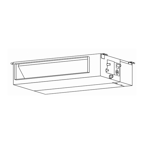
Indoor Unit Installation Indoor Unit Parts Air inlet Electric control cabinet Air filter(on selected models) Drain hose Air outlet Refrigerant connecting pipe Fig. 4.1 Safety Precautions CAUTION WARNING • Securely install the indoor unit on a structure • Install the indoor and outdoor units, cables that can sustain its weight. - Page 9 Installation place > 11.8in(30cm) Strong and durable ceiling >0.8in(2cm) Indoor unit Right Left side side > 0.8in(2cm) Service access Ceiling >4in(10cm) >11.8in(30cm) Floor Maintenance space > Air outlet 11.8 (30cm) > (20cm) Air inlet 23.6 x23.6 (60cmx60cm) checking orifice Fig. 4.2 Step 2: Hang indoor unit.
- Page 10 Air inlet dimensions Air filter Descending ventilation opening and mounted hook Air filter Electric control box Fig. 4.3 Table.4-1 (unit: mm/inch) Outline dimension air outlet opening size air return opening size Size of mounted lug MODEL (Btu/h) 9K/12K 700/27.6 200/7.9 506/19.9 450/17.7 152/6...
- Page 11 Screw nut CAUTION Shockproof cushion The unit body must be completely aligned with the hole. Ensure that the unit and the hole are Overhang part Washer the same size before moving on. Hanging screw bolt 2. Install and fit pipes and wires after you have Fig.
- Page 12 Step 4: Adjust the air inlet direction Step 5: Fresh air duct installation (from rear side to under-side). Dimension : Duct joint for fresh air 1. Take off the ventilation panel and flange. Air return flange MODLE 18-60 Ø125mm(4.92”) Ø160mm(6.3”) Ventilation panel Fig.
- Page 13 Outdoor Unit Installation √ The area must be free of combustible gases Outdoor Unit Installation Instructions and chemicals. √ The pipe length between the outdoor and Step 1: Select installation location. indoor unit may not exceed the maximum The outdoor unit should be installed in the allowable pipe length.
- Page 14 Split Type Outdoor Unit (Refer to Fig 5.4, 5.5, 5.6, 5.10 and Table 5.1) Fig. 5.4 Fig. 5.5 Fig. 5.6 Table 5.1: Length Specifications of Split Type Outdoor Unit (unit: mm/inch) Outdoor Unit Dimensions Mounting Dimensions W x H x D Distance A Distance B 770x555x300 (30.3x21.85x11.81)
- Page 15 NOTE: The minimum distance between the 2. Insert the drain joint into the hole in the base outdoor unit and walls described in the pan of the unit. installation guide does not apply to airtight 3. Rotate the drain joint 90° until it clicks in place rooms.
-
Page 16: Drainpipe Installation
Drainpipe Installation The drainpipe is used to drain water away from NOTE ON DRAINPIPE INSTALLATION the unit. Improper installation may cause unit • When using an extended drainpipe, tighten and property damage. the indoor connection with an additional protection tube. This prevents it from CAUTION pulling loose. - Page 17 Units with a pump. 3. Using a 65-mm (2.5”) core drill, drill a hole in the wall. Make sure that the hole is drilled at 1. Remove the test cover. a slight downward angle, so that the outdoor Fill the water pan with 2 liters of water. end of the hole is lower than the indoor end by about 12mm (0.5”).
-
Page 18: Refrigerant Piping Connection
Refrigerant Piping Connection Safety Precautions Notes On Pipe Length and Elevation Ensure that the length of the refrigerant pipe, the number of bends, and the drop height between WARNING the indoor and outdoor units meets the • All field piping must be completed by a requirements shown in Table 7.1: licensed technician and must comply with the local and national regulations. - Page 19 CAUTION CAUTION Oil traps If the outdoor unit is installed higher than the • indoor unit: If the indoor unit is installed higher than the outdoor unit: -It is recommended that vertical suction risers not be upsized. Proper oil return to the -If oil flows back into the outdoor unit’s compressor should be maintained with suction compressor, this might cause liquid...
-
Page 20: Refrigerant Piping Connection Instructions
Table 7.2 Step1: Cut pipes When preparing refrigerant pipes, take extra Permitted length care to cut and flare them properly. This will Total piping length 18K+18K 30m/98’ L+Max (L1, L2) 24K+24K 50m/164’ ensure efficient operation and minimize the 30K+30K need for future maintenance. (farthest distance from 15m/49’... - Page 21 Step 3: Flare pipe ends Table 7.5: PIPING EXTENSION BEYOND FLARE FORM Pipe Tightening Flare dimension (A) Flare shape Proper flaring is essential to achieve an torque (Unit: mm/Inch) gauge airtight seal. Min. Max. 1. After removing burrs from cut pipe, seal 18-20 N.m 90 °...
- Page 22 NOTE: Use both a spanner and a torque wrench NOTE: DO NOT intertwine signal cable with when connecting or disconnecting pipes to/from other wires. While bundling these items the unit. together, do not intertwine or cross the signal cable with any other wiring. 7.
-
Page 23: Outdoor Unit Wiring
Wiring To prevent distortion when the compressor starts Safety Precautions (you can find the unit’s power information on WARNING the rating sticker): • The unit must be connected to the main • Disconnect the power supply before outlet. Normally, the power supply must working on the unit. -
Page 24: Indoor Unit Wiring
Table 8.2: Other World Regions Indoor Unit Wiring Rated Current of Nominal Cross-Sectional 1. Prepare the cable for connection Appliance (A) Area (mm a. Using wire strippers, strip the rubber jacket 0.75 ≤ from both ends of the signal cable to reveal about 15cm (5.9”) of the wire. - Page 25 CAUTION While connecting the wires, please strictly • - Press “CONFIRM”. The air conditioning follow the wiring diagram. unit will then start the fan for airflow The refrigerant circuit can become very • automatic adjustment. hot. Keep the interconnection cable away from the copper tube.
-
Page 26: Power Specifications
Power Specifications NOTE: Electric auxiliary heating type circuit breaker/fuse need to add more than 10 A. Indoor Power Supply Specifications ≤18K MODEL(Btu/h) 19K~24K 25K~36K 37K~60K 61K~72K PHASE 1 Phase 1 Phase 1 Phase 1 Phase 1 Phase POWER VOLT 208-240V 208-240V 208-240V 208-240V 208-240V CIRCUIT BREAKER/ 25/20 32/25... - Page 27 ≤36K ≤36K MODEL(Btu/h) 37K~72K 37K~72K PHASE 1 Phase 1 Phase 1 Phase 1 Phase POWER (indoor) VOLT 208-240V 208-240V 208-240V 208-240V CIRCUIT BREAKER/FUSE(A) 15/10 15/10 15/10 15/10 PHASE 3 Phase 3 Phase 3 Phase 3 Phase POWER (outdoor) VOLT 380-420V 380-420V 208-240V 208-240V...
- Page 28 Air Evacuation 4. Turn on the vacuum pump to evacuate the Safety Precautions system. 5. Run the vacuum for at least 15 minutes, or until the Compound Meter reads -76cmHG CAUTION (-1x10⁵Pa). 6. Close the manifold gauge’s Low Pressure • Use a vacuum pump with a gauge reading valve and turn off the vacuum pump.
- Page 29 Note On Adding Refrigerant CAUTION • Refrigerant charging must be performed after wiring, vacuuming, and the leak testing. DO NOT exceed the maximum allowable quantity of refrigerant or overcharge the system. • Doing so can damage the unit or impact it’s functioning. •...
-
Page 30: Test Run
Test Run f. Check to see that the drainage system is Before Test Run unimpeded and draining smoothly. A test run must be performed after the entire g. Ensure there is no vibration or abnormal system has been completely installed. Confirm noise during operation. -
Page 31: Impedance Information
Impedance Information (Applicable to Middle East Countries only) NOTE: To be in compliance with EN61000-3-11, the product MTI-48HWN1-R shall be connected only to a supply of the system impedance: Zsys = 0.267802236 Ω or less. Before connecting the product to public power network, please consult your local power supply authority to ensure the power network meet above requirement. - Page 32 Table of Contents Owner’s Manual Safety Precautions ............04 SAFETY FIRST Indoor Unit Parts and Major Functions ..05 Manual Operations ...........07...
- Page 33 Care and Maintenance ......08 a. Unit Maintenance ........08 b. How to Clean the Air Filter .......08 c. Repairing Refrigerant Leaks ......09 d. Preparation for Periods of Non-use ..09 Troubleshooting ......... 10 a. Common Problems ......10 b. Troubleshooting Tips ......11 European Disposal Guidelines ..............
- Page 34 Safety Precautions Thank you for purchasing this air conditioner. This manual will provide you with information on how to operate, maintain, and troubleshoot your air conditioner. Following the instructions will ensure the proper function and extended lifespan of your unit. Please pay attention to the following signs: Failure to observe a warning may result in death.
- Page 35 Indoor Unit Parts And Major Functions Unit Parts Air inlet Electric control cabinet Air filter(on some models) Air outlet Drain hose Refrigerant connecting pipe Fig. 2.1 Operating Conditions Use the system under the following temperatures for safe and effective operation. If the air conditioner is used under different conditions, it may malfunction or become less efficient.
- Page 36 Features Default Setting Louver Angle Memory Function (Optional) When the air conditioner restarts after a power Some models are designed with a louver angle failure, it will default to the factory settings memory function. When the unit restarts after a (AUTO mode, AUTO fan, 24°C (76°F)).
- Page 37 Manual Operations This display panel on the indoor unit can be used to operate the unit in case the remote control has been misplaced or is out of batteries. Manual button LED display Operation indicator Infrared receiver Alarm indicator Timer indicator DEF./FAN (defrost/fan) indicator...
-
Page 38: Care And Maintenance
Care And Maintenance WARNING: DO NOT REMOVE OR Safety Precautions CLEAN THE FILTER BY YOURSELF Contact an authorized service technician for • repair or maintenance. Improper repair and Removing and cleaning the filter can be maintenance may cause water leakage, dangerous. -
Page 39: Repairing Refrigerant Leaks
3. Remove the air filter. Repairing Refrigerant Leaks 4. Clean the air filter by vacuuming the surface or washing it in warm water with mild WARNING detergent. A. If using a vacuum cleaner, the inlet side If the refrigerant leaks, turn off the air •... -
Page 40: Troubleshooting
Troubleshooting CAUTIONS If one of the following conditions occurs, switch off the power supply immediately and contact your dealer for further assistance. The operation light continues to flash rapidly after the unit has been restarted. • The remote control buttons do not work. •... - Page 41 Problem Possible Causes Dust is emitted from The unit may accumulate dust during extended periods of non-use, which either the indoor or will be emitted when the unit is turned on. This can be mitigated by covering outdoor unit the unit during long periods of inactivity. The unit may absorb odors from the environment (such as furniture, cooking, The unit emits a cigarettes, etc.) which will be emitted during operations.
- Page 42 The number Timer Error of flashes Cause Number indicator Code per second Indoor EEPROM (Electrically Erasable Programmable Read-Only Memory) error Indoor fan speed malfunction Indoor room temperature sensor error Evaporator coil temperature sensor error Refrigerant leak detection system malfunction Water level alarm malfunction Outdoor condenser pipe sensor error Indoor unit communication malfunction ...
-
Page 43: European Disposal Guidelines
European Disposal Guidelines Users in European Countries may be required to properly dispose of this unit. This appliance contains refrigerant and other potentially hazardous materials. When disposing of this appliance, the law requires special collection and treatment. DO NOT dispose of this product as household waste or unsorted municipal waste. - Page 44 Page 16 ...
- Page 45 Page 17 ...
- Page 46 Page 18 ...
Need help?
Do you have a question about the BSBSM24CMO and is the answer not in the manual?
Questions and answers