Advertisement
Quick Links
Instruction Manual
REMOTE POWER
MUTE
ALARM
Data, drawings, and other material contained herein are proprietary to Cross Technologies, Inc.,
but may be reproduced or duplicated without the prior permission of Cross Technologies, Inc.
for purposes of operating the equipment.
When ordering parts from Cross Technologies, Inc., be sure to include the equipment
model number, equipment serial number, and a description of the part.
F=2050.000
MENU
G=+00.0
RF=A
EXECUTE
C
T
ROSS
ECHNOLOGIES, INC.
6170 Shiloh Road
Alpharetta, Georgia 30005
(770) 886-8005
FAX (770) 886-7964
Toll Free 888-900-5588
WEB www.crosstechnologies.com
E-MAIL info@crosstechnologies.com
Model 2015-123
Upconverter
November 2009 Rev A
MODEL 2015
UPCONVERTER
C
T
ROSS
ECHNOLOGIES INC.
Advertisement

Related Manuals for Cross Technologies 2015-123


Summary of Contents for Cross Technologies 2015-123
- Page 1 ALARM Data, drawings, and other material contained herein are proprietary to Cross Technologies, Inc., but may be reproduced or duplicated without the prior permission of Cross Technologies, Inc. for purposes of operating the equipment. When ordering parts from Cross Technologies, Inc., be sure to include the equipment model number, equipment serial number, and a description of the part.
- Page 2 WARRANTY - The following warranty applies to all Cross Technologies, Inc. products. All Cross Technologies, Inc. products are warranted against defective materials and workmanship for a period of one year after shipment to customer. Cross Technologies, Inc.’s obligation under this warranty is limited to repairing or, at Cross Technologies, Inc.’s option, replacing parts, subassemblies, or entire assemblies.
- Page 3 1.0 General 1.1 Equipment Description The 2015-123 Upconverter converts 70 ± 18 MHz to 2025 to 2300 MHz in 1kHz, 10kHz, or 125kHz steps (user selectable) with low group delay and flat frequency response. Synthesized local oscillators (LO) provide very low phase noise and ±0.01 ppm stability frequency selection.
- Page 4 1.2 Technical Characteristics TABLE 1.1 2015-123 Upconverter Specifications* Input Characteristics Impedance/Return Loss /18 dB Frequency 70 ± 18 MHZ Input Level -40 to -10 dBm Output Characteristics Impedance/Return Loss 50 /10 dB Frequency 2025 to 2300 MHz Output level 0 to -20 dBm...
- Page 5 A) Remote serial interface Protocol: RS-232C, 9600 baud rate, no parity, 8 data bits, 1 start bit, and 1 stop bit. (RS-232C, RS-422, or RS-485 - option -Q) M&C Cable Diagram - Cross Technologies Frequency Converters Male DB-9 Female DB-9 2015/16/17 M&C Port...
- Page 6 Table 1.3 lists the status requests for the 2015-95 and briefly describes them. PLEASE NOTE: The two character {aa}(00-31) prefix, in the table below, should be used ONLY when RS-485, (OPTION-Q), is selected. Table 1.3 2015-123 Status Re e quests Requests Command...
- Page 7 C) Commands - Table 1.2 lists the commands for the 2015-123 and briefly describes them. After a command is sent the 2015-123 sends a return “>” indicating the command has been received and executed. General Command Format - The general command format is {aaCND...}, where:...
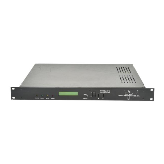
- Page 8 16 inch deep chassis. A switching, ± 12, +24, +5 VDC power supply provides power for the assembly. The 2015-123 can be secured to a rack using the 4 holes on the front panel. Figure 2.1 shows how the 2015-123 is assembled.
- Page 9 2025-2300 MHz 90-260 VAC, 47-60 Hz. -10 to -40 dBm input 0 to -20 dBm output 0 to -20 dBm output FIGURE 2.2 2015-123 Rear Panel Inputs and Outputs Table 2.1 J10 Pinouts (RS-485/RS-422/RS-232C)* Table 2.1 J10 Description Rx+ (RS-232C)
- Page 10 2.4 Installation / Operation 2.4.1 Installing and Operating the 2015-123 Upconverter 1.) Connect a -10 dBm to -40 dBm, 70MHz signal to IF IN, J4 (Figure 2.2) 2.) Connect the RF OUT A, J101, and RF OUT B, J102, to the external equipment.
- Page 11 3.The present frequency, gain, and selected RF output of the upconverter is shown. F = 2050.000 G = +00.0 RF = A The unit is now operational and ready for any changes the operator may desire. 2015-123 Manual, Rev.A Page 11 11/12/09...
- Page 12 MENU AND INDICATE YOU WANT TO SAVE THE CHANGES. THE CARRIER IS MUTED WHEN FREQUENCY IS CHANGED. When the display indicates the value desired you can push the Menu/Execute switch to the next item: UP INLVL = -20 2015-123 Manual, Rev.A Page 12 11/12/09...
- Page 13 G = +10.0 By using the horizontal rocker switch the cursor can be moved left or right. Pressing the Up/Down switch down will toggle the display digit selected until you have the desired gain. 2015-123 Manual, Rev.A Page 13 11/12/09...
- Page 14 An alarm condition for will occur if the local oscillator phase lock loop (PLL) comes out of lock. The Mute LED will light if you select to mute the Tx Signal and the Remote LED will light when you select the Remote mode. 2015-123 Manual, Rev.A Page 14 11/12/09...
- Page 15 ADDRESS = 00 SCROLL <> Menu 12 Select remote address for SCROLL PUSH BUTTON unit (RS485 only) SAVE SETTINGS? Save? When go to end SCROLL <> PUSH BUTTON FIGURE 2.5 Menu Display and Sequence 2015-123 Manual, Rev.A Page 15 11/12/09...
- Page 16 G. Top Cover - There are no serviceable parts inside the product so, the Top Cover should not be removed. If the Top Cover is removed the ground strap and associated screw MUST BE REINSTALLED prior to Top Cover screw replacement. FAILURE TO DO this may cause INGRESS and/or EGRESS emission problems. 2015-123 Manual, Rev.A Page 16 11/12/09...
- Page 17 ROSS ECHNOLOGIES, INC. 6170 Shiloh Road Alpharetta, Georgia 30005 (770) 886-8005 FAX (770) 886-7964 Toll Free 888-900-5588 WEB www.crosstechnologies.com E-MAIL info@crosstechnologies.com Printed in USA 2015-123 Manual, Rev.A Page 17 11/12/09...
Need help?
Do you have a question about the 2015-123 and is the answer not in the manual?
Questions and answers