Advertisement
Quick Links
Instruction Manual
DOWNCONVERTER
UPCONVERTER
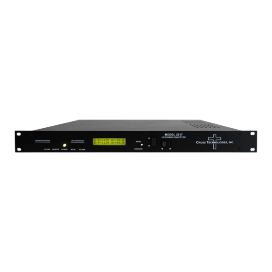
ALARM
REMOTE
POWER
MUTE
Data, drawings, and other material contained herein are proprietary to Cross Technologies, Inc., but may be
reproduced or duplicated without the prior permission of Cross Technologies, Inc. for purposes of operating
the equipment. Printed in USA.
When ordering parts from Cross Technologies, Inc., be sure to include the equipment model number,
equipment serial number, and a description of the part.
U F=1055
G=+10.0
D F=2155
G=+15.0
ALARM
C
T
ROSS
ECHNOLOGIES, INC.
6170 Shiloh Road
Alpharetta, Georgia 30005
(770) 886-8005
FAX (770) 886-7964
Toll Free 888-900-5588
WEB www.crosstechnologies.com
E-MAIL info@crosstechnologies.com
Model 2017-0923#-370
MODEL 2017
UP/DOWNCONVERTER
MENU
EXECUTE
Up/Downconverter
February 2022, Rev. 0
C
T
ROSS
ECHNOLOGIES INC.
Advertisement

Related Manuals for Cross Technologies 2017-0923 370 Series


Summary of Contents for Cross Technologies 2017-0923 370 Series
- Page 1 POWER MUTE ALARM Data, drawings, and other material contained herein are proprietary to Cross Technologies, Inc., but may be reproduced or duplicated without the prior permission of Cross Technologies, Inc. for purposes of operating the equipment. Printed in USA. When ordering parts from Cross Technologies, Inc., be sure to include the equipment model number, equipment serial number, and a description of the part.
-
Page 2: Table Of Contents
WARRANTY - The following warranty applies to all Cross Technologies, Inc. products. All Cross Technologies, Inc. products are warranted against defective materials and workmanship for a period of one year after shipment to customer. Cross Technologies, Inc.’s obligation under this warranty is limited to repairing or, at Cross Technologies, Inc.’s option, replacing parts, subassemblies, or entire assemblies. -
Page 3: General
MODEL 2017-0923#-370 Up/Downconverter 1.0 General 1.1 Equipment Description The 2017-0923#-370 L-band Up/Downconverter has a 370 Mhz to 950-2300 MHz upconverter channel and a 950-2300 MHz to 370 MHz downconverter channel with 1 MHz step size tuning, low group delay and flat frequency response. - Page 4 1.2 Technical Characteristics EQUIPMENT SPECIFICATIONS S * SPECIFICATIONS* Input Characteristics Input UP, L DOWN, L 75 /18 dB 50 /12 dB Impedance/Return Loss Frequency 370 ± 18 MHz 0 0 .95-2.30GHz Noise Figure, Max. 20 dB @ max gain 15 dB @ max gain Input Level range -30 to -10 dBm -30 to -10 dBm...
- Page 5 A) Remote serial interface Protocol: RS-232C, 9600 baud rate, no parity, 8 data bits, 1 start bit, and 1 stop bit. (RS-232C, RS-422, or RS-485 - option -Q) M&C Cable Diagram - Cross Technologies Frequency Converters Male DB-9 Female DB-9 2015/16/17 M&CPort...
- Page 6 B) Status Requests Table 1.1 lists the status requests for the 2017-0923#-370 and briefly describes them. PLEASE NOTE: The two character {aa}(00-31) prefix, in the table below, should be used ONLY when RS-485, (OPTION-Q), is selected. Table 1.1 2017-0923#-370 S S tatus Table 1.1 2017-0923#-370 Status Requests 2017-0923#-370 Status Request t s...
- Page 7 Table 1.2 (2017-0923#-370 Commands, continued from page 7...) Table 1.2 2017-0923#-370 Comman n ds Commands - continued d from continued from page 7 Command Syntax* Description Insert 10MHz on UP RF (option -E) {aaC5x} where: (N/A option -E1) • x = 0 to disable 10 MHz upconverter insertion on RF[J5] •...
- Page 8 C) Commands Table 1.2 lists the commands for the 2017-0923#-370 and briefly describes them. After a command is sent the 2017-0923#-370 sends a return “>” indicating the command has been received and executed. General Command Format - The general command format is {aaCND...}, where: { = start byte aa = address (RS-485 only option -Q) C = 1 character, either C (command) or S (status)
-
Page 9: Installation
2.0 Installation 2.1 Mechanical The 2017-0923#-370 consists of one RF/Controller PCB housed in a 1 RU (1 3/4 inch high) by 16 inch deep chassis. A switching, ± 12, +5, +24 VDC power supply provides power for the assemblies. The 2017-0923#-370 can be secured to a rack using the 4 holes on the front panel. - Page 10 2.2 Rear Panel Input/Output Signals and Control - Figure 2.1 shows the input and output connectors on the rear panel. J3 - 10 MHz EXT REF INPUT (Option -E) 10 MHz external reference input, +3 dBm ± 3 dBm, 75 ohms, BNC female connector.
- Page 11 2.3 Front Panel Controls and Indicators - The following are the front panel controls and indicators. DS3 - DOWN ALARM LED DS1 - REMOTE LED LCD DISPLAY S1 - MENU/EXECUTE BUTTON Red LED indicates Yellow LED indicates Display shows Up and Press this to get into Program mode downconverter alarm.
-
Page 12: Operation
2.4 Installation / Operation 2.4.1 Installing and Operating the 2017-0923#-370, Upconverter Section 1.) Connect a -30 dBm to -10 dBm signal to IF In, J4 (Figure 2.1). 2.) Connect the RF OUT, J5, to the external equipment. 3.) Connect 100-240 ±10% VAC, 47 - 63 Hz to AC on the back panel. 4.) Set the desired output frequency (See Section 2.5 Menu Settings). - Page 13 Option E1 Units with option E1 operate as described above but also have an Auto mode. When in auto mode the unit will detect and select the external 10 MHz signal if it is present and at least +3 dBm. If the external 10 MHz signal falls below 1 dBm (+/- 1 dB) the unit will automatically switch to the internal 10 MHz reference.
- Page 14 FUSE DRAWER SPARE FUSE AC Fuse - 2 amp slow blow (Type T), 5 mm X 20 mm FUSE INPUT 100-240± 10%VAC TYPE T 2A GDC 47-63 Hz 250 VOLT 2A MAX FOR 100 - 240 V~ Figure 2.3 Fuse Location and Spare Fuse 2017-0923#-370 Page 14 02/15/22...
-
Page 15: Menu Settings
2.5 Menu Settings 2.5.1 Functions - This section describes operation of the front panel controls. There are three operator switches, the LCD display and alarm indicator LEDs. All functions for the equipment are controlled by these components. The functions are (see Figure 2.2): Power Up Normal Display Menu 1... - Page 16 2.5.2 Power-On Settings NOTE: THE LAST STATUS OF A UNIT IS RETAINED EVEN WHEN POWER IS REMOVED. WHEN POWER IS RESTORED, THE UNIT WILL RETURN TO IT'S PREVIOUS SETTINGS. When power is first applied, the LCD display goes through three steps. 1.
- Page 17 2.5.4 Frequency Changes At any time during the modification process, if you have made a mistake and do not wish to save the changes you have made, do not press the Menu/Execute switch; simply do nothing for approximately 30 seconds, and the system will return to the normal operating mode or scroll to “R”...
- Page 18 2.5.5 Gain Changes When you get to this menu note that the gain changes will be made as you make them but if you do not wish to save the changes you have made, scroll to “R” and push the menu/Execute switch and select “NO” in the “SAVE SETTINGS?”...
- Page 19 2.5.5.2 Downconverter Gain To set the downconverter gain, first push the Menu/Execute switch to get to the gain setting: Operate the Menu/Execute switch until you get to the menu item you want to change. See Figure 2.4 for the sequence of menu options. The following display is for changing the downconverter gain.
- Page 20 ON POWER UP 2017-0923#-370E1W8X Power Up 4.00 NORMAL DISPLAY F = 1055 G = +10.0 Normal Display F = 2155 G = +15.0 PUSH BUTTON PUSHING MENU/EXECUTE SEQUENCE UP F = 1450 SCROLL <> Menu 1 Up Frequency SCROLL PUSH BUTTON SCROLL <>...
-
Page 21: Environmental Use Information
3.0 Environmental Use Information A. Rack-Mounting - To mount this equipment in a rack, please refer to the installation instructions located in the user manual furnished by the manufacturer of your equipment rack. B. Mechanical loading - Mounting of equipment in a rack should be such that a hazardous condition does not exist due to uneven weight distribution. - Page 22 ROSS ECHNOLOGIES, INC. 6170 Shiloh Road Alpharetta, Georgia 30005 (770) 886-8005 FAX (770) 886-7964 Toll Free 888-900-5588 WEB www.crosstechnologies.com E-MAIL info@crosstechnologies.com Printed in USA 2017-0923#-370 Page 22 02/15/22...
Need help?
Do you have a question about the 2017-0923 370 Series and is the answer not in the manual?
Questions and answers