Advertisement
Quick Links
Instruction Manual
DOWNCONVERTER
UPCONVERTER
ALARM
REMOTE
POWER
MUTE
Data, drawings, and other material contained herein are proprietary to Cross Technologies, Inc., but may be
reproduced or duplicated without the prior permission of Cross Technologies, Inc. for purposes of operating
the equipment.
When ordering parts from Cross Technologies, Inc., be sure to include the equipment model number,
equipment serial number, and a description of the part.
U F=1725
G=+10.0
D F=2675
G=+25.0
ALARM
C
T
ROSS
ECHNOLOGIES, INC.
6170 Shiloh Road
Alpharetta, Georgia 30005
(770) 886-8005
FAX (770) 886-7964
Toll Free 888-900-5588
WEB www.crosstechnologies.com
E-MAIL info@crosstechnologies.com
Model 2017-1727-140
Up/Downconverter
MODEL 2017
UP/DOWNCONVERTER
MENU
EXECUTE
February 2018, Rev. 0
C
T
ROSS
ECHNOLOGIES INC.
Advertisement

Related Manuals for Cross Technologies 2017-1727-140


Summary of Contents for Cross Technologies 2017-1727-140
- Page 1 POWER MUTE ALARM Data, drawings, and other material contained herein are proprietary to Cross Technologies, Inc., but may be reproduced or duplicated without the prior permission of Cross Technologies, Inc. for purposes of operating the equipment. When ordering parts from Cross Technologies, Inc., be sure to include the equipment model number, equipment serial number, and a description of the part.
-
Page 2: Table Of Contents
WARRANTY - The following warranty applies to all Cross Technologies, Inc. products. All Cross Technologies, Inc. products are warranted against defective materials and workmanship for a period of one year after shipment to customer. Cross Technologies, Inc.’s obligation under this warranty is limited to repairing or, at Cross Technologies, Inc.’s option, replacing parts, subassemblies, or entire assemblies. -
Page 3: General
1.1 Equipment Description The 2017-1727-140 L, S-band Up/Downconverter converts 140 ± 20 MHz to 0.95-1.75 GHz GHz (Up) and 2.0- 2.7 to 140 ± 20 MHz (Down) in 1 MHz steps (100 or 125 kHz steps optional). Multi-function switches select the frequency, gain ( upconverter -10 to +30 dB;... -
Page 4: Technical Characteristics
1.2 Technical Characteristics TABLE 1.0 2017-1727-140 Up/Downconverter Specifications* --------UPCONVERTER-------- --------DOWNCONVERTER-------- Input Characteristics Input Characteristics (L) 50 Ω /14 dB Impedance/Return Loss 50 Ω /14 dB Impedance/Return Loss Frequency 140 ± 20 MHZ Frequency 2.0 to 2.7 GHz Noise Figure, Maximum 20 dB @ max. - Page 5 TABLE 1.0 2017-1727-140 Up/Downconverter Specifications... Continued from page 4 Available Options: External 10 MHz Reference input & output High Stability (±0.01ppm) Internal Reference RF/RF Monitor Ports (Front) External Temp 0C to +50C X or X1 125 kHz or 100 kHz step size Remote &...
-
Page 6: Monitor & Control Interface
Alarm Relay: Normally Open Not Used Alarm Relay: Normally Closed B) Status Requests Table 1.1 lists the status requests for the 2017-1727-140 and briefly describes them. Table 1.1 2017-1727-140 St t atus Table 1.1 2017-1727-140 Status Requests 2017-1727-140 Status Req q uests... - Page 7 C) Commands Table 1.2 lists the commands for the 2017-1727-140 and briefly describes them. After a command is sent the 2017-1727-140 sends a return “>” indicating the command has been received and executed. General Command Format - The general command format is {aaCND...}, where:...
-
Page 8: Installation
The 2017-1727-140 consists of one RF/Controller PCB housed in a 1 RU (1 3/4 inch high) by 16 inch deep chassis. A switching, ± 12, +5, +24 VDC power supply provides power for the assemblies. The 2017-1727-140 can be secured to a rack using the 4 holes on the front panel. Figure 2.0 shows how the 2017-1727-140 is assembled. - Page 9 140 ±10 MHz input, -40 to -10 dBm in, 0.95 - 1.75 GHz see Table 2.2. -20 to 0 dBm out, see Table 2.2. Figure 2.1 Model 2017-1727-140 Rear Panel I/O’s TABLE 2.1 J1 1 0 J10 Pinouts (RS-232C/422/485*) Function...
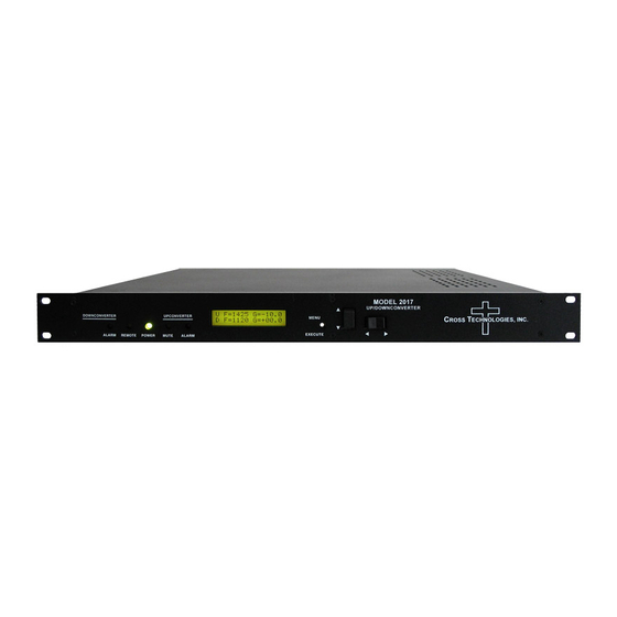
- Page 10 Does not function adjusted. Does not function in the in the normal display mode normal display mode Figure 2.2 Model 2017-1727-140 Front Panel Controls and Indicators 2017-1727-140 Manual, Rev. 0 Page 10 02/14/18...
-
Page 11: Operation
2.4 Installation / Operation 2.4.1 Installing and Operating the 2017-1727-140, Upconverter Section 1.) Connect a -40 dBm to -10 dBm signal to IF In, J4 (Figure 2.1). 2.) Connect the RF OUT, J5, to the external equipment. 3.) Connect 100-240 ±10 VAC, 47 - 63 Hz to AC on the back panel. -
Page 12: Menu Settings
If programming is initiated and no operator action takes place for approximately 12 seconds (before the final press of the Menu/Execute switch) the display will revert to its previous status and you will need to start over. 2017-1727-140 Manual, Rev. 0 Page 12 02/14/18... - Page 13 For other functions such Mute on/off, the vertical switch will alternately turn the function on or off regardless of the direction operated. 2017-1727-140 Manual, Rev. 0 Page 13 02/14/18...
- Page 14 Selecting Y will save the new settings. Selecting N will revert to the previous settings. Pushing the Menu/Execute switch then takes you to the : F=1725 G=+10.0 F=2675 G=+25.0 Figure 2.4 shows all the menu items and how to make changes. 2017-1727-140 Manual, Rev. 0 Page 14 02/14/18...
- Page 15 Selecting Y will save the new settings. Selecting N will revert to the previous settings. Pushing the Menu/Execute switch then takes you to the : F=1725 G=+10.0 F=2675 G=+25.0 Figure 2.4 shows all the menu items and how to make changes. 2017-1727-140 Manual, Rev. 0 Page 15 02/14/18...
- Page 16 Figure 2.4 shows all the menu items and how to make changes. 2.5.5 Alarm Indications An alarm condition for will occur if any local oscillator phase lock loop (PLL) comes out of lock. 2017-1727-140 Manual, Rev. 0 Page 16 02/14/18...
- Page 17 (option T) SCROLL PUSH BUTTON SCROLL <> Save? When “R” is selected in any SAVE SETTINGS? above menu or after last menu item PUSH BUTTON SCROLL PUSH BUTTON Figure 2.4 Menu Display and Sequence 2017-1727-140 Manual, Rev. 0 Page 17 02/14/18...
- Page 18 ROSS ECHNOLOGIES, INC. 6170 Shiloh Road Alpharetta, Georgia 30005 (770) 886-8005 FAX (770) 886-7964 Toll Free 888-900-5588 WEB www.crosstechnologies.com E-MAIL info@crosstechnologies.com Printed in USA 2017-1727-140 Manual, Rev. 0 Page 18 02/14/18...
Need help?
Do you have a question about the 2017-1727-140 and is the answer not in the manual?
Questions and answers