Keysight Technologies 34937A User Manual
General purpose switch modules
Hide thumbs
Also See for 34937A:
- User manual (29 pages) ,
- User manual (19 pages) ,
- User manual (31 pages)
Table of Contents
Advertisement
Quick Links
Advertisement
Table of Contents

Related Manuals for Keysight Technologies 34937A


Summary of Contents for Keysight Technologies 34937A
- Page 1 Keysight 34937A-34939A General Purpose Switch Modules User’s Guide...
- Page 2 EXPRESS OR IMPLIED, WITH REGARD agreement and written consent from customarily provided to the public. TO THIS MANUAL AND ANY Keysight Technologies as governed by Accordingly, Keysight provides the INFORMATION CONTAINED HEREIN, United States and international Software to U.S. government INCLUDING BUT NOT LIMITED TO THE copyright laws.
-
Page 3: Safety Symbols
Off (mains supply) On (mains supply) Three phase alternating current Presence of a laser device Equipment protected throughout by Protective earth (ground) terminal double insulation or reinforced insulation Product is sensitive to electrostatic Caution, hot surface discharge Keysight 34937A-34939A User’s Guide... -
Page 4: Additional Safety Notices
Pollution Degree 1: No pollution or only dry, non-conductive pollution occurs. NOTE The pollution has no influence (on insulation). Pollution Degree 2: Normally only non-conductive pollution occurs. Occasionally, a temporary conductivity (leakage current between isolated conductors) caused by condensation can be expected. Keysight 34937A-34939A User’s Guide... - Page 5 Failure to recognize and observe normal safety precautions could result in personal injury or death. Safety of any system incorporating the equipment is the responsibility of the WARNING assembler of the system. Keysight 34937A-34939A User’s Guide...
- Page 6 Dangerous voltage levels capable of causing death, may be present on a WARNING channel. Use extreme caution when handling and testing and adjusting this instrument. Any voltages greater than 30 Vrms, 42.4 Vpeak and 60 Vdc are considered hazardous (IEC 61010-1). Keysight 34937A-34939A User’s Guide...
- Page 7 Use a dry cloth or one slightly dampened with water (or 70% Isopropyl Alcohol) to clean the external case parts. Do not attempt to clean internally. Allow any moisture to evaporate prior to energizing the instrument. Keysight 34937A-34939A User’s Guide...
- Page 8 ENVIRONMENTAL HEALTH & SAFETY: When any channel is connected to a WARNING hazardous voltage source, the instrument and the device under test should be supervised, following local EHS practices to restrict access. Keysight 34937A-34939A User’s Guide...
-
Page 9: Environmental Conditions
40°C, decreases linearly to 37% RH at 55°C Altitude Up to 2,000 m Pollution degree 1 or 2 [a] From 40°C to 55°C, the maximum % Relative Humidity follows the line of constant dew point. Keysight 34937A-34939A User’s Guide... -
Page 10: Regulatory Markings
This symbol is a South Korean Class A EMC Declaration. This is a Class A The RCM mark is a registered instrument suitable for professional trademark of the Australian use and in electromagnetic Communications and Media Authority. environment outside of the home. Keysight 34937A-34939A User’s Guide... - Page 11 This mark indicates product has been designed to meet the requirements of Universal recycling symbol. "IP x y", where "x" is the solid particle protection and "y" is the liquid ingress protection. Keysight 34937A-34939A User’s Guide...
-
Page 12: Waste Electrical And Electronic Equipment (Weee) Directive 2002/96/Ec
To contact Keysight for sales and technical support, refer to the support links on the following Keysight websites: – www.keysight.com/find/34980a (product-specific information and support, software and documentation updates) – www.keysight.com/find/assist (worldwide contact information for repair and service) Keysight 34937A-34939A User’s Guide... -
Page 13: Table Of Contents
......17 34937A, 34938A and 34939A SCPI Programming Examples ..20 Opening and Closing Channels . - Page 14 ........39 34980A Current Limiting Graphs ......42 Keysight 34937A-34939A User’s Guide...
-
Page 15: General Purpose Switch Modules
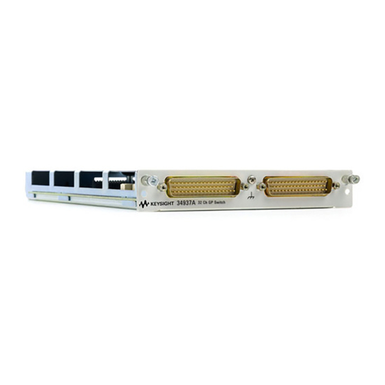
34939A 64-Channel High-Density Form A – The 34937A provides independent control of 32 relays, including: – Twenty-eight Form C relays, each rated for 1 A at 60 VA per channel – Four Form A (SPST) relays, each rated for 5 A at 150 VA per channel. -
Page 16: Operating Considerations
34938T terminal blocks have solder pads for adding snubber circuits for the 5 A relays to reduce the reactive transients. See the drawings on page 24 page 31 for the locations of snubber circuit pads and installation information about a snubber circuit. Keysight 34937A-34939A User’s Guide... -
Page 17: Hardware Power-Fail Jumper
34890A. Hardware Power-Fail Jumper A hardware jumper on the 34937A and 34938A modules allows you to define the power-failure states for the modules’ 5 A latching relays. Depending on the position of the jumper, the 5 A relays will either open or maintain state when system power failure occurs. - Page 18 After all circuits are discharged and no hazardous voltages remain, remove the sheet metal cover from the module and move the position of the jumper mounted on the module. See the figure below for the jumper’s location on the module. Keysight 34937A-34939A User’s Guide...
- Page 19 Keysight 34937A-34939A User’s Guide...
-
Page 20: 34937A, 34938A And 34939A Scpi Programming Examples
4. If this command is sent to a module other than the 34937A or 34938A, “NONE” is returned (no error is generated). In particular, the position of the power-fail jumper on the 34939A module cannot be queried using this commmand. -
Page 21: Reading Cycle Count And Resetting Modules To Power-On State
7 and 16 for a module in slot 1. DIAGnostic:RELay:CYCLes:CLEar (@1007,1016) Example: Resetting Module(s) to power-on state (all modules) The following command resets a module in slot 4 to its power-on state. SYSTem:CPON 4 Keysight 34937A-34939A User’s Guide... -
Page 22: 34937A 32-Channel Gp Switch Module
34937A 32-Channel GP Switch Module The 34937A general-purpose switch module provides independent control of: – Twenty-eight Form C (SPDT) latching relays rated at 1 A – Four Form A (SPST) latching relays rated at 5 A. You can set the power-failure state for these 5 A relays (see “Hardware Power-Fail Jumper”... -
Page 23: 34937A D-Sub Connectors
11 NO 14 NO No Connect 17 3 NC 6 NC 9 NC 12 NC 29 NO 3 Common 6 Common 9 Common 12 Common 22 29 Common 2 3 NO 6 NO 9 NO 12 NO Keysight 34937A-34939A User’s Guide... - Page 24 No Connect 17 17 NC 20 NC 23 NC 26 NC 31 NO 17 Common 21 20 Common 32 23 Common 27 26 Common 22 31 Common 2 17 NO 20 NO 23 NO 26 NO Keysight 34937A-34939A User’s Guide...
-
Page 25: 34937T Terminal Block
The circuits may consist of resistors, capacitors, varistors, or other elements as needed to reduce the switching voltage and current transients inherent in reactive circuits. These pads are connected to Channels 29 - 32 for 2 Form A circuits. Keysight 34937A-34939A User’s Guide... - Page 26 Never operate the instrument without the terminal block covers securely installed. Use caution to prevent operators from accessing any external circuits, test fixtures, cables or whenever hazardous voltages may be present. Keysight 34937A-34939A User’s Guide...
- Page 27 – AWM Class II B or A/B – external/interconnecting wires (single- or multiple-conductor constructions with a jacket) and potentially subject to mechanical abuse (Canada) – AWM Style Use – external interconnection of electronic equipment or appliances (US) Keysight 34937A-34939A User’s Guide...
- Page 28 / snubber circuits are appropriate for the signal being tested. Failure to do so may result in hazardous conditions such as fire or shock and could lead to personal injury or death. Keysight 34937A-34939A User’s Guide...
-
Page 29: 34938A 20-Channel High-Current Gp Switch Module
A temperature sensor on these modules triggers system interrupts when NOTE high-carry current-induced heat on the modules reaches a threshold of 70 °C. See description of the “HOT” annunciator on page 34938A Simplified Schematic Channel 001 (5A Form A) Channel 020 (5A Form A) Keysight 34937A-34939A User’s Guide... -
Page 30: 34938A D-Sub Connectors
4C 10NO 10C 10NO 10C Channel Channel Channel Channel Pins Channel Pins 1Common 3Common 5Common 7Common 9Common 10NO 1Common 4Common 6Common 8Common 10Common 10NO 2Common 4Common 6Common 8Common 10Common Reserved 2Common 4Common 7Common 9Common 3Common 5Common 7Common 9Common No Connect Keysight 34937A-34939A User’s Guide... - Page 31 18NO 20NO 11Common 14Common 16Common 18Common 20Common 12NO 14NO 16NO 18NO 20NO 12Common 14Common 16Common 18Common 20Common 12NO 14NO 17NO 19NO Reserved 12Common 14Common 17Common 19Common 13NO 15NO 17NO 19NO 13Common 15Common 17Common 19Common No Connect Keysight 34937A-34939A User’s Guide...
-
Page 32: 34938T Terminal Block
Pads for user-supplied snubber circuity to alleviate reactive transients. The circuits may consist of resistors, capacitors, varistors, or other elements as needed to reduce the switching voltage and current transients inherent in reactive circuits. Keysight 34937A-34939A User’s Guide... - Page 33 Never operate the instrument without the terminal block covers securely installed. Use caution to prevent operators from accessing any external circuits, test fixtures, cables or whenever hazardous voltages may be present. Keysight 34937A-34939A User’s Guide...
- Page 34 – AWM Class II B or A/B – external/interconnecting wires (single- or multiple-conductor constructions with a jacket) and potentially subject to mechanical abuse (Canada) – AWM Style Use – external interconnection of electronic equipment or appliances (US) Keysight 34937A-34939A User’s Guide...
- Page 35 / snubber circuits are appropriate for the signal being tested. Failure to do so may result in hazardous conditions such as fire or shock and could lead to personal injury or death. Keysight 34937A-34939A User’s Guide...
-
Page 36: 34939A 64-Channel High-Density Form-A Gp Switch Module
A temperature sensor on these modules triggers system interrupts when NOTE high-carry current-induced heat on the modules reaches a threshold of 70 °C. See description of the “HOT” annunciator on page 34939A Simplified Schematic Channel 001 (1A Form A) Channel 064 (1A Form A) Keysight 34937A-34939A User’s Guide... -
Page 37: 34939A D-Sub Connectors
13 Common 7 20 Common 51 27 Common 17 No Connect 60 7 NO 14 NO 21 NO 28 NO No Connect 65 7 Common 14 Common 47 21 Common 13 28 Common 37 No Connect 66 Keysight 34937A-34939A User’s Guide... - Page 38 45 Common 29 52 Common 5 59 Common 41 No Connect 60 39 NO 46 NO 53 NO 60 NO No Connect 65 39 Common 13 46 Common 9 53 Common 45 60 Common 23 No Connect 66 Keysight 34937A-34939A User’s Guide...
- Page 39 C NO C NO C NO C NO C NO C NO C NO C NO C NO C NO C NO C NO C NO C NO C NO C NO C NO C NO C NO C NO C NO C NO Keysight 34937A-34939A User’s Guide...
- Page 40 Never operate the instrument without the terminal block covers securely installed. Use caution to prevent operators from accessing any external circuits, test fixtures, cables or whenever hazardous voltages may be present. Keysight 34937A-34939A User’s Guide...
- Page 41 – AWM Class II B or A/B – external/interconnecting wires (single- or multiple-conductor constructions with a jacket) and potentially subject to mechanical abuse (Canada) – AWM Style Use – external interconnection of electronic equipment or appliances (US) Keysight 34937A-34939A User’s Guide...
- Page 42 – Volt-Hertz limit 10 – Volt-Hertz limit 10 – Initial closed channel resistance 50m – Initial closed channel resistance 50m – Differential Voltage FormC - FormA – Differential Voltage FormC - Form A 300Vrms or VDC 100Vrms or VDC Keysight 34937A-34939A User’s Guide...
- Page 43 The overcurrent protection devices will be rated, or the snubber circuits will limit the current, according to: 1. DC or AC RMS voltage, channel-to-channel or channel-to-earth. 2. Limited to 6 W of channel resistance power loss per module. Keysight 34937A-34939A User’s Guide...
- Page 44 5A (switch) / 7A (carry) 150VA per channel 150VA per channel The overcurrent protection devices will be rated, or the snubber circuits will limit the current, according to: 1. DC or AC RMS voltage, channel-to-channel or channel-to-earth. Keysight 34937A-34939A User’s Guide...
- Page 45 Initial closed channel resistance: <125m Initial closed channel resistance: <125m The overcurrent protection devices will be rated, or the snubber circuits will limit the current, according to: 1. Limited to 6 W of channel resistance power loss per module. Keysight 34937A-34939A User’s Guide...
- Page 46 THIS PAGE HAS BEEN INTENTIONALLY LEFT BLANK. Keysight 34937A-34939A User’s Guide...
- Page 47 34938A connector pinouts temperature sensor description simplified schematic snubber circuitry terminal block wiring log 34939A connector pinouts description simplified schematic terminal block wiring log connector pinouts 34937A 34938A 34939A D-sub pinouts 34937A 34938A 34939A jumper pinouts Keysight 34937A-34939A User’s Guide...
- Page 48 THIS PAGE HAS BEEN INTENTIONALLY LEFT BLANK. Keysight 34937A-34939A User’s Guide...
- Page 49 This information is subject to change without notice. Always refer to the Keysight website for the latest revision. © Keysight Technologies 2016-2022 Edition 4, Aug 2022 Printed in Malaysia 34980-90037 www.keysight.com...
Need help?
Do you have a question about the 34937A and is the answer not in the manual?
Questions and answers