Table of Contents
Advertisement
Advertisement
Table of Contents

Related Manuals for Keysight Technologies L4490A


Summary of Contents for Keysight Technologies L4490A
- Page 1 User Guide Keysight L4490A/L4491A RF Switch Platform...
- Page 2 WITHOUT NOTICE, IN FUTURE EDI- without prior agreement and written con- ment of Defense FAR Supplement TIONS. FURTHER, TO THE MAXIMUM sent from Keysight Technologies, Inc. as (“DFARS”) 227.7202, the U.S. govern- EXTENT PERMITTED BY APPLICABLE governed by United States and interna-...
- Page 4 Safety Information Do Not Remove Instrument Cover The following general safety precau- tions must be observed during all Only qualified, service-trained person- phases of operation of this instrument. nel who are aware of the hazards Failure to comply with these precau- involved should remove instrument tions or with specific warnings or oper- covers.
-
Page 5: Safety Symbols
Safety Symbols A CAUTION denotes a hazard. It calls attention to an operating The CSA mark is a registered trade- procedure or practice, that, if not mark of the Canadian Standards Asso- correctly performed or adhered to South Korean Class A EMC Declara- ciation and indicates compliance to could result in damage to the tion. -
Page 7: Table Of Contents
L4490A/L4491A Use Model ........ - Page 8 ............. . 88 Getting Started with the L4490A/L4491A Web-Enabled Interface ..88 Connecting to the Instrument and Viewing its Home Page.
- Page 9 5 Additional Operating Information L4490A/L4491A SCPI Command Summary ......128 Y1150A - Y1155A Switch Control Tables ......132 Y1150A Switch Control.
- Page 10 LED Drive Indicators ..........148 L4490A/L4491A Digital IO and Relay Driver Option 004 ....149 Digital I/O Functions .
-
Page 11: About The Instrument
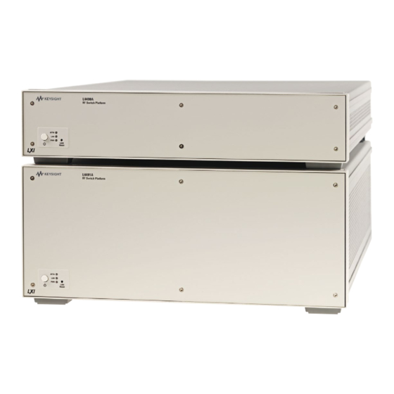
L4491A are optimized for use with the Keysight family of RF/microwave switches and attenuators. The L4490A is a 2U, and the L4491A is a 4U LXI Class C instrument. LXI, an acronym for LAN eXtensions for Instrumentation is an instrumentation standard for devices that use the Ethernet (LAN) as their primary communication interface. -
Page 12: L4490A/L4491A Use Model
About the Instrument L4490A/L4491A Use Model L4490A/L4491A Use Model The use model for the L4490A and L4491A RF switch platform and for this manual is: 1 Inventory and identification of standard L4490A/L4491A components and recommended switch/attenuator accessories (Chapter 1). 2 Connecting switches/attenuators to their brackets and installation of the switch/bracket assembly in the RF switch platform (Chapter 1). -
Page 13: Equipment Inventory
Input Power and Operating Environment The input power, operating environment, and storage environment specifications for the L4490A/L4491A are listed in Table 1-1. Refer to the instrument data sheet for a complete listing of specifications. The data sheets can be found on the Web www.Keysight.com/find/L449xA... -
Page 14: Recommended Accessories
40°C Storage Environment: -40°C to 70°C The L4490A/L4491A should be operated in an indoor environment where temperature and humidity are controlled. Condensation can pose a potential shock hazard. Condensation can occur when the modules are moved from a cold to a warm environment, or if the temperature and/or humidity of the environment changes quickly. - Page 15 5091-2679E (with 324) 8766K - 7K 5959-7831 Y1155A [2] Y1175A (12-pin Viking) 8768K - 9K Y1155A [1] 8767M - 9M 5988-2477EN 10-pin DIP Y1175A Y1153A [2] [Y1158A] U9397A,C 5989-6088EN standard solder Y1155A [8] Y1170A:L4491A terminals Y1171A:L4490A Keysight L4490A/L4491A User’s Guide...
- Page 16 N1811TL: Serial numbers MY07244660 and later N1812UL: Serial numbers MY07240668 and later (3) Bracket kits apply to the L4490A/L4491A. The kits include pre-assembled control cables and hardware for mounting switches/attenuators to the brackets and the bracket assemblies to the chassis. Each bracket kit includes hardware for mounting five switches.
-
Page 17: Installing Switches/Attenuators In The Rf Switch Platform
The Cable (only) kits are primarily used with the 34945A/L4445A, but can also be used with the L4490A/L4491A. These cables must be assembled. Refer to Appendix A for cable assembly instructions.4445A, but can also be used with the L4490A and L4491A. These cables must be assembled. Refer to Appendix A for cable assembly instructions. - Page 18 It is not necessary to remove the feet from the bottom cover. Use care when handling the L4490A and L4491A chassis with the top and bottom covers removed as components within the chassis are susceptible to damage from ESD.
-
Page 19: Bracket-Switch Assembly
The Y1170A bracket (kit) is required for the L4491A platform and the Y1171A bracket (kit) is required for the L4490A platform and the L4491A platform with Option 006. The Y1170A and Y1171A kits contain hardware for installing five switches. - Page 20 U937A,C 8762 switch mounting thread size = M3 x 0.5 screw alignment is through switch and into bracket screw alignment is through switch and into bracket Figure 1-2. Connecting Switches to the Y1170A and Y1171A Brackets. Keysight L4490A/L4491A User’s Guide...
-
Page 21: Y1172 Bracket
Figure 1-3 shows the bracket contained in the Y1172A mounting kit and the mounting position for the supported switches. The Y1172A bracket (kit) is used with both the L4490A and L4491A platforms. The Y1172A kit contains hardware for installing five switches. -
Page 22: Y1173 Bracket
Figure 1-4 shows the bracket contained in the Y1173A mounting kit and the mounting position for the supported switches. The Y1173A bracket (kit) is used with both the L4490A and L4491A platforms. The Y1173A kit contains hardware for installing six switches (two switches per bracket). -
Page 23: Y1174 Bracket
Figure 1-5 shows the bracket contained in the Y1174A mounting kit and the mounting positions for the supported attenuators. The Y1174A bracket (kit) is used with both the L4490A and L4491A platforms. The Y1174A kit contains hardware for installing five attenuators. -
Page 24: Y1175 Bracket
Figure 1-6 shows the bracket contained in the Y1175A mounting kit and the mounting positions for the supported switches and attenuators. The Y1175A bracket (kit) is used with both the L4490A and L4491A platforms. The Y1175A kit contains hardware for installing five switches or attenuators. -
Page 25: L4490A/L4491A Switch Trays And Options
The switch tray is a grid with spacings of 45.72 mm x 45.72 mm between any two holes in the ‘x’ and ‘y’ directions. Bracket mounting requires the L4490A top and bottom covers to be removed (Figure 1-1). Screw alignment is upward through the bottom of the tray and into the bracket’s captive nut. -
Page 26: L4491A Standard Mounting Bays (Option 005)
(kit screws require T-20 Torx driver) Figure 1-8. Example Switch and Attenuator Positioning within the L4490A. L4491A Standard Mounting Bays (Option 005) Figure 1-9 show the switch bays and bracket mounting locations for the L4491A with standard Option 005. - Page 27 ‘x’ and ‘y’ directions. Screw alignment in the rear mounting tray is downward through the bracket and into the captive nut on the tray. Figure 1-10 shows example placement of switches and attenuators within the L4491A. Keysight L4490A/L4491A User’s Guide...
-
Page 28: L4491A Bottom Switch Tray (Option 006)
= M4x0.7 Figure 1-10. Example Switch and Attenuator Positioning: L4491A with Option 005. L4491A Bottom Switch Tray (Option 006) Figure 1-11 shows the switch tray and bracket mounting location for L4491A Option 006. Keysight L4490A/L4491A User’s Guide... - Page 29 L4491A Option 006 platforms without Digital IO and Relay Drive Option 004 will have a small increase in the bracket mounting area. Example placement of switches and attenuators on the bottom tray is similar to those shown in Figure 1-7 for the L4490A. Keysight L4490A/L4491A User’s Guide...
-
Page 30: L4491A Multiport Front Panel (Option 001)
Figure 1-12 shows L4491A multiport front panel Option 001. In order to use Option 001 with standard switch bay Option 005, the rail assembly behind the front panel must be removed. Figure 1-12 shows the assembly location and how it is removed. Keysight L4490A/L4491A User’s Guide... - Page 31 87104A-C 87106A-C 87406B 87204A-C 87206A-C 87606B L7104A-C L7106A-C L74204A-C L74206A-C Figure 1-12. Multiport Front Panel Option 001 with Standard Bay Option 005. Keysight L4490A/L4491A User’s Guide...
-
Page 32: L4490A/L4491A Bracket Layout Guidelines
About the Instrument Installing Switches/Attenuators in the RF Switch Platform L4490A/L4491A Bracket Layout Guidelines Switches installed in the L4490A platform or in the L4491A platform with Option 006 can be mounted in any orientation that optimizes or simplifies switch or attenuator wiring. -
Page 33: Hardware Configuration
Hardware Configuration This chapter contains network, cabling, channel configuration, and switch wiring information for the L4490A/L4491A RF Switch Platform and supported switches/attenuators. Refer to this chapter for specific information on: - choosing between a private LAN and site LAN network... -
Page 34: Network Configuration
Network Configuration This section contains information for choosing a network configuration (a private or site LAN) in which to use the L4490A/L4491A. Selecting a LAN Network For the purposes of this manual, a private (isolated) LAN network is defined as a... -
Page 35: Site Lan Considerations
IT departments. When using a site LAN, consult your IT department regarding LAN configuration and security issues. Instrument Configuration Figure 2-1 shows the components and interconnections of the L4490A/L4491A RF switch platform configuration. Keysight L4490A/L4491A User’s Guide... - Page 36 Hardware Configuration Instrument Configuration Hub/Switch = standard LAN cables LAN cross-over cable for direct PC - L4490A/L4491A connection if PC is non Auto-MDIX (included) L4490A/L4491A DC Output Power Supplies (user applications) 12V: 3A fused +24V supplied from L4490A/L4491A 24V: 0.6A (42A Max.)
-
Page 37: The 34945Ext Module
34945EXT to External Power Supplies. All slave 34945EXT modules external to the L4490A or L4491A chassis must use an external power supply or supplies. Note that the supply voltage (+24V, +12V, +5V) applies to all distribution board banks on the 34945EXT. - Page 38 Bank 3 Bank 3 Ch 1141-1148 Ch 1241-1248 Ch 1151-1158 Ch 1251-1258 Bank 4 Bank 4 Y1152A Ch 1161-1168 Ch 1261-1268 Ch 1171-1178 Ch 1271-1278 Y1153A Y1154A Y1155A Figure 2-2. The 34945EXT Module and Y1150A-Y1155A Distribution Boards. Keysight L4490A/L4491A User’s Guide...
-
Page 39: Channel Numbering
Hardware Configuration Channel Numbering The 34945EXT in the L4490A/L4491A RF switch platform uses the following channel numbering scheme: 1<ext #><channel> where: ext # is the 34945EXT module and is a single digit in the range of 1 (master) to 2 (slave - a second 34945EXT in the L4491A). Note that up to seven slave EXT modules may be used per master 34945EXT in the L4490A/L4491A. -
Page 40: Relay/Channel Relationship
When channel pairing is not enabled (e.g. for single-coil drive), the channel numbers within the bank are not consecutive. The range of the 16 channels remains 1-8/11-18 (bank 1) ... 61-68/71-78 (bank 4). See the previous page. Keysight L4490A/L4491A User’s Guide... -
Page 41: Internal/External Power Supply Considerations
The master 34945EXT (Figure 2-1) and optional second 34945EXT (Option 002) can receive their power from either the internal +24V supply of the L4490A/L4491A or from an external supply. When using the internal +24V supply as the channel drive source, the switching current or the switching and quiescent currents drawn from the supply must not exceed the supply’s specification of 600... -
Page 42: External Supply
87104/87106 switch is: [34945EXT quiescent current from 24V] + [switch quiescent current] + [switching current] [24V: 1.2W / 24V = 50 mA] + [50 mA] + [200 mA] = 300 mA (15 ms pulse, 100 mA qui.) Keysight L4490A/L4491A User’s Guide... -
Page 43: Keysight Switch/Attenuator Configuration
Only general information is provided. Refer to the reference documents listed in Table 1-2 for more information on the individual switches. Refer also to Table 1-2 for the number of switches allowed per distribution board. Keysight L4490A/L4491A User’s Guide... -
Page 44: Keysight N1810 / N1811 / N1812 Series Coaxial Switches
Figure 2-3. Keysight N1810 / N1811 / N1812 Pin Definition and Orientation. The pin information for the Keysight switches shown in Figure 2-3 was taken from the reference documents listed in Table 1-2. Refer to Table 1-2 for information on accessing these documents from the Keysight web-site. Keysight L4490A/L4491A User’s Guide... -
Page 45: Keysight 87104/87106/87406 - L7104/L7106/L7204/L7206 Coaxial Switches
SW1 - Path 5 SW2 - Path 5 SW1 - Path 6 SW2 - Path6 Not Used Not Used Not Used Not Used Figure 2-4. Keysight 871x / 874x / L71x / L72x Pin Definition and Orientation. Keysight L4490A/L4491A User’s Guide... - Page 46 Keysight Switch/Attenuator Configuration The pin information for the Keysight switches shown in Figure 2-4 was taken from the reference documents listed in Table 1-2. Refer to Table 1-2 for information on accessing these documents from the Keysight web-site. Keysight L4490A/L4491A User’s Guide...
-
Page 47: Keysight 87204 / 87206/ 87606 Series Coaxial Switches
SW1 - Close 4 SW3 - Ind A switches. See Figure 2-3 for N181x SW1 - Open 4 SW3 - Ind B connector pin definitions. Figure 2-5 Keysight 87204 / 87206 / 87606 Pin Definition and Orientation. Keysight L4490A/L4491A User’s Guide... -
Page 48: Keysight 8767/8/9M Microwave Single-Pole Multi-Throw Switches
Table 1-2 for information on accessing these documents from the Keysight web-site. Keysight 8767/8/9M Microwave Single-Pole Multi-Throw Switches Figure 2-6 identifies the terminals of the 8767/8/9M switches and typical connections to the Y1153A distribution board (* 8767M shown). Keysight L4490A/L4491A User’s Guide... - Page 49 Select Bypass Select Bypass Select Bypass Select Bypass Select Bypass Switch actuating pin Pin dip wire color White Gray Black Violet Brn/Wht Blue Yellow Orange Org/Wht Yel/Wht Red/Wht Figure 2-6. Keysight 8767/8/9M Port Definitions and Connections. Keysight L4490A/L4491A User’s Guide...
- Page 50 1-2. Refer to Table 1-2 for information on accessing these documents from the Keysight web-site. Keysight 84904/6/7 K/L and 84904/5/8M Programmable Step Attenuators Figure 2-7 identifies the pins of the 84904/6/7 K/L and 84904/5/8M step attenuators and their connections to the Y1153A distribution board. Keysight L4490A/L4491A User’s Guide...
- Page 51 P102 Thru 2 P101 Atten 3 P102 Atten 3 P101 Thru 3 P102 Thru 3 P101Atten 4 P102 Atten 4 P101 Thru 4 P102 Thru 4 Figure 2-7. Keysight 84904/6/7 K/L Attenuator Pin Definitions and Connections. Keysight L4490A/L4491A User’s Guide...
-
Page 52: Keysight 8494/5/6/7 Programmable Step Attenuators
1-2. Refer to Table 1-2 for information on accessing these documents from the Keysight web-site. Keysight 8494/5/6/7 Programmable Step Attenuators Figure 2-8 identifies the pins of the 8494/5/6/7 step attenuators and typical connections to the Y1153A distribution board. Keysight L4490A/L4491A User’s Guide... - Page 53 The terminal information for the Keysight switches shown in Figure 2-8 was taken from the reference documents listed in Table 1-2. Refer to Table 1-2 for information on accessing these documents from the Keysight web site. Keysight L4490A/L4491A User’s Guide...
-
Page 54: Keysight 849Xg/H/K Programmable Step Attenuators Option 016
Hardware Configuration Keysight Switch/Attenuator Configuration Keysight 849xG/H/K Programmable Step Attenuators Option 016 Figure 2-9 identifies the pins of the 8494/5/6/7 Option 016 Step Attenuators and typical connections to the Y1153A distribution board. Keysight L4490A/L4491A User’s Guide... - Page 55 P101 Atten 3 P102 Atten 3 P101 Thru 3 P102 Thru 3 P101Atten 4 P102 Atten 4 P101 Thru 4 P102 Thru 4 Figure 2-9. Keysight 8494 /5 / 6 / 7 Attenuator Pin Definitions and Connections. Keysight L4490A/L4491A User’s Guide...
-
Page 56: Keysight 87222 And L7222 Coaxial Switches
Figure 2-9. Keysight 87222 / L7222 Pin Definition and Orientation. The pin information for the Keysight switches shown in Figure 2-9 was taken from the reference documents listed in Table 1-2. Refer to Table 1-2 for information on accessing these documents from the Keysight web-site. Keysight L4490A/L4491A User’s Guide... -
Page 57: Keysight 8762 / 8763 / 8764 Series Coaxial Switches
Y1155A distribution board (w/ position indication). Y1155A (SW# - B) (SW# - A) 8762A/B/C 8764A/B/C 8763A/B/C L4490A: use Y1171A bracket Y1155A Distribution Board LED Connector Pins L4491A: use Y1170A bracket (paired) LED1 Connector LED2 Connector Definition Definition... -
Page 58: Keysight 8765 Series Coaxial Switches
Table 1-2. Refer to Table 1-2 for information on accessing these documents from the Keysight web-site. Keysight 8765 Series Coaxial Switches Figure 2-11 identifies the terminals of the 8765 switches and typical connections to the Y1155A distribution board (with position indication). Keysight L4490A/L4491A User’s Guide... - Page 59 Hardware Configuration Y1155A (SW# - B) (SW# - A) L4490A: use Y1171A bracket L4491A: use Y1170A bracket 8765A/B/C/D The’ common negative’ and ‘polarity reversal’ configurations of the 8765 series switch are not supported. Y1155A Distribution Board LED Connector Pins 8765F...
-
Page 60: Keysight 8766/7/8/9K Microwave Single-Pole Multi-Throw Switches
Hardware Configuration Keysight Switch/Attenuator Configuration Keysight 8766/7/8/9K Microwave Single-Pole Multi-Throw Switches Figure 2-12 identifies the terminals of the 8766/7/8/9K switches and typical connections to the Y1155A distribution board (* 8767K shown). Keysight L4490A/L4491A User’s Guide... - Page 61 Section state Select Bypass Select Bypass Sele Bypass Select Bypass Select Bypass Std. Viking pin Std. Viking wire color White Brown Green Black Blue Orange Yellow Violet Gray Wht/Red Figure 2-12. Keysight 8766/7/8/9K Section Definitions and Connections. Keysight L4490A/L4491A User’s Guide...
-
Page 62: Keysight U9397A / U9397C Fet Solid State Switches
Y1155A Distribution Board LED Connector Pins (un-paired) LED1 Connector LED2 Connector Definition Definition Definition Definition SW11 Distribution Board LED Connector SW12 SW13 SW14 SW15 SW16 SW17 SW18 Figure 2-13. Keysight U9397A / U9397C Connector Definitions and Connections. Keysight L4490A/L4491A User’s Guide... - Page 63 Hardware Configuration The terminal information for the Keysight switches shown in Figure 2-13 was taken from the reference documents listed in Table 1-2. Refer to Table 1-2 for information on accessing these documents from the Keysight web-site. Keysight L4490A/L4491A User’s Guide...
- Page 64 Hardware Configuration Keysight Switch/Attenuator Configuration Keysight L4490A/L4491A User’s Guide...
-
Page 65: Software Installation And Configuration
Software Installation and Configuration This chapter contains information on IO libraries and drivers required to program the L4490A/L4491A from selected development environments. The chapter also provides information on configuring the instrument’s LAN and GPIB interfaces and on updating the instrument firmware. -
Page 66: Software Requirements
Software Installation and Configuration Software Requirements Software Requirements The manner and environments available to program the L4490A/L4491A are dependent upon the IO libraries and drivers installed. The IO software included with the L4490A/L4491A is contained on the following CDs: - Keysight Automation-Ready CD: Keysight IO Libraries Suite 15.0 - Keysight L4490A/L4491A Product Reference CD-ROM: ... -
Page 67: Installing The Keysight Io Libraries
The Keysight IO Libraries must be installed prior to installing drivers (e.g. IVI-C, IVI-COM) from the L4490A/L4491A Product Reference CD or from any other source. The IO Libraries are contained on the Keysight Automation-Ready CD or may be down- oaded from the Keysight website at: http://www.Keysight.com/find/iosuite... -
Page 68: Installing Instrument Drivers
L4490A/L4491A using Microsoft development environments, Keysight VEE, or National Instruments LabVIEW (see Table 3-1). Insert the Keysight L4490A/L4491A Product Reference CD-ROM into your computer. The installa- tion program will open the window shown in Figure 3-1. Keysight L4490A/L4491A User’s Guide... -
Page 69: Adding Instruments To The Interface
GPIB interfaces using the Keysight IO Libraries ‘Connection Expert’ utility. Configuring the LAN Interface With the L4490A/L4491A turned on and connected to the PC (Chapter 2: Figure 2-1), start the Connection Expert utility by clicking the ‘IO (control)’ icon and selecting “Keysight Connection Expert”... -
Page 70: Locating The Instruments
Software Installation and Configuration Adding Instruments to the Interface The procedure for using Keysight Connection Expert to locate and configure the L4490A/L4491A is independent of the type of network you are using (private or site) and the network devices present (switches or routers). - Page 71 Figure 3-3. Keysight Connection Expert (ACE) Opening Window. To search the network for instruments, click on “Add Instrument” located on the Connection Expert tool bar. From the “Add Instrument” window, select the LAN (TCPIP0) interface and click on ‘OK’. See Figure 3-4. Keysight L4490A/L4491A User’s Guide...
- Page 72 The instruments appear in the Keysight Connection Expert Explorer pane (Figure 3-3). Selecting the instrument in the Explorer pane dis- plays its properties in the Properties pane. Keysight L4490A/L4491A User’s Guide...
-
Page 73: About Ip Addresses And Host Names
If there is a DHCP server on the network, the server will assign the address to the instrument. If there is not a DHCP server on the network, the L4490A/L4491A will automati- cally determine the address to use. The address will be in the range 169.254.1.1 to 169.254.255.255. -
Page 74: Configuring The Gpib Interface
TCPIP0::169.254.44.88::inst0::INSTR or host name: TCPIP0::A-L449XA-00118.Keysight.com::inst0::INSTR A powerful tool for programming the L4490A/L4491A is the instrument’s Web interface. The Web interface provides full access to L4490A/L4491A functionality and its IO command log feature logs (SCPI) commands sent to the instrument via interface dialog boxes. The commands can then be copied and transferred to other development environments. -
Page 75: Adding Instruments To The Gpib Configuration
(note: factory-set address = 9) and click ‘OK’. Connection Expert will attempt to establish a communication path to the instru- ment. If the L4490A/L4491A is at the address specified, the instrument will be added to the list of GPIB-configured instruments. -
Page 76: The Gpib Address String
Software Installation and Configuration Adding Instruments to the Interface If the L4490A/L4491A GPIB address is unknown, the address can be queried from the LAN interface by sending the following command from the ‘Interactive IO’ or ‘SCPI Command Interface’ window: SYSTEM:COMMunicate:GPIB:ADDRess? See “Using Interactive IO”... -
Page 77: Using Interactive Io
Using Interactive IO The Connection Expert ‘Interactive IO’ utility provides another method (Table 3-1) of sending commands to the L4490A/L4491A. Similar to the ‘SCPI Command Interface’ window of the web-enabled interface, Interactive IO allows you to send any command in the L4490A/L4491A SCPI command set to the instrument. -
Page 78: Applying Power
Applying Power If the Interactive IO window is used to send the self-test (*TST?) command to the L4490A/L4491A, the “timeout” period may have to be increased to allow the results to be returned. This is done using the ‘Options’ link on the Interactive IO window. - Page 79 Software Installation and Configuration Color Instrument State ATTN Instrument identification. Activated from instrument Web interface: Green (flashing) ON: Turn on Front Panel Interface Indicator Green OFF: Turn off Front Panel Interface Indicator Keysight L4490A/L4491A User’s Guide...
-
Page 80: Lan Default Configuration
None (disabled) Firmware and Driver Updates irmware and driver updates (when available) for the L4490A/L4491A are avail- able via the Web. This section contains information for locating and downloading the updates to your computer, and then installing the updates in the instrument. -
Page 81: Downloading The Firmware Update
Depending on the interface to the L4490A/L4491A, the firmware update utility will require the instrument’s LAN or GPIB address. Note this address before starting the utility. - Page 82 When there is no longer instrument activity as indicated by the front panel LEDs (Table 3-3), cycle power on the instrument. To verify that the L4490A/L4491A controller box and the 34945EXT have the same firmware revision, the following commands can be sent from the Interactive...
-
Page 83: Updating The L4491A With Option 002
Figure 3-9. Specifying the Instrument Address. Following a firmware update, Keysight Connection Expert may report that the L4490A/L4491A configuration has changed. This is represented by a yellow triangle and an exclamation point (!) next to the updated instrument. Select the instrument name, select ‘Change Properties’, and then select either ‘Test Connection’... - Page 84 (step 4), turn off the L4491A and disconnect the power cord. Remove the ribbon cable from the second 34945EXT and reconnect it to the master (right side) 34945EXT. Re-insert the excess cable in the clamps and re-insert and tighten the cable connector screws. Keysight L4490A/L4491A User’s Guide...
-
Page 85: Downloading Ivi-Com Driver And Labview Driver Updates
34945EXT. Connect the external 34945EXT (one at a time) directly to the L4490A or L4491A controller box with the ribbon cable that is used to connect to the master 34945EXT (see Figure 2-1). - Page 86 Software Installation and Configuration Downloading IVI-COM Driver and LabVIEW Driver Updates Keysight L4490A/L4491A User’s Guide...
-
Page 87: Introduction To Programming
Introduction to Programming Introduction to Programming This chapter contains information on using the L4490A/L4491A built-in Web interface for switch and attenuator control. Refer to this chapter for specific information on: - opening the instrument’s Web interface - the instrument’s home Web page... -
Page 88: Getting Started With The L4490A/L4491A Web-Enabled Interface
Figure 4-1. The L4490A/L4491A Programming Home Page. Getting Started with the L4490A/L4491A Web-Enabled Interface By far, the easiest way to begin programming the L4490A/L4491A RF Switch Platform is through the instrument’s built-in Web server. As mentioned in Chapter 3 (Table 3-1), the Web server’s instrument interface requires a ... -
Page 89: Connecting To The Instrument And Viewing Its Home Page
PC, and only if the PC does not have Auto-MDIX (Gigabit Ethernet). Obtaining the Host Name or IP Address In order to connect a Web browser to the instrument, the L4490A/L4491A host name or IP address is required. The host name set at the factory has the format: a-l449xa-yyyyy where ‘yyyyy’... - Page 90 Introduction to Programming Getting Started with the L4490A/L4491A Web-Enabled Interface SCPI programming interface SCPI command logging selects the 34945EXT (1-2) switches per distribution board SYST:CPON 1 bank diagram 34945EXT configuration distribution board installed Distribution board configuration Switch/Attenuator channel configuration Figure 4-2. 34945EXT, Distribution Board, and Channel Configuration.
-
Page 91: Observe Only / Allow Full Control
The remote module is the 34945EXT module within the L4490A/L4491A (Figure 2-1). L4491A Option 002 adds a second 34945EXT to the L4491A platform. The L4490A/L4491A can support up to eight 34945EXT modules external to the switch platform. The remote module currently selected is the one configured by the interface. -
Page 92: Switch/Attenuator Channel Configuration Window
Introduction to Programming Getting Started with the L4490A/L4491A Web-Enabled Interface This feature is limited to external channel drive sources (power supplies) with the capability to drive multiple channels. - boot/reset channel drive - this parameter specifies the channel drive source setting following a re-boot (power-up) or reset of the instrument. -
Page 93: Bank (Distribution Board) Configuration Window
- Preset Bank - this command sets the bank configuration to conform to the switches supported by the distribution board installed. The programming of any switch or attenuator must begin by presetting the bank. Keysight L4490A/L4491A User’s Guide... -
Page 94: Legend
It may not indicate the actual switch state as the switch position is not electronically verified. SCPI Command Interface The SCPI programming interface window (Figures 4-2 and 4-6) enables you to send any command in the L4490A/L4491A (34945EXT) SCPI command set to the instrument. Keysight L4490A/L4491A User’s Guide... -
Page 95: Logging Scpi Commands
Commands sent from any IO environment (e.g. Web windows, Keysight Connection Expert Interactive IO, Microsoft development environments) to the instrument are logged. Query commands (those which return data) sent from any Web interface window are not logged. Keysight L4490A/L4491A User’s Guide... - Page 96 Introduction to Programming Getting Started with the L4490A/L4491A Web-Enabled Interface Figure 4-7. Logging SCPI Commands within the System Overview Window. To view commands, select “Read/Clear Remote I/O Traffic Log” and then select “Generate Report” after the desired configuration has been set. Logged commands are listed in the order received by the instrument.
-
Page 97: System Verification
34945EXT relative to position indicator signals received from the switch. To begin using the L4490A/L4491A RF switch platform as quickly as possible or to minimize troubleshooting, it is highly recommended that the path to each 34945EXT bank be verified prior to installing the distribution board and any switches or attenuators. -
Page 98: Running The Verification Sequence
Running the Verification Sequence The verification sequence is executed from the L4490A/L4491A Web interface. As mentioned in Chapter 3, the L4490A/L4491A must be connected to the PC through one of the LAN configurations shown in Figure 2-1. The Web interface is not available from the GPIB interface. - Page 99 The button does not appear with any other distribution board. Once the verification sequence successfully completes, the sequence can be deleted. The (verification) sequence is defined for the bank each time the “Create Verification Sequence” button is selected. Keysight L4490A/L4491A User’s Guide...
- Page 100 Introduction to Programming System Verification ROUT:SEQ:DEF AG_Y1156A_VERIFY_RM1_BANK1 ROUT:RMOD:DRIV:SOUR INT,(@1100) ROUT:RMOD:BANK:PRES 1,(@1100) Keysight L4490A/L4491A User’s Guide...
-
Page 101: Position Indicator Verification
Securely fasten the verification board within the bank using the terminal screws. 3 Turn on the L4490A/L4491A (if turned off) and open the web interface. Select the ‘Browser Web Control’ page and select ‘Allow Full Control’. 4 In the ‘Browser Web Control’ window, locate the bank and Y1156A programming diagram. - Page 102 Introduction to Programming System Verification ROUT:SEQ:DEF POS_IND_VERIFY ROUT:RMOD:BANK:PRES 1,(@1100) ROUT:RMOD:DRIV:SOUR INT,(@1100) Keysight L4490A/L4491A User’s Guide...
-
Page 103: Switch And Attenuator Programming
(If L4491A Option 002 is installed, the channel drive source must be set to EXTernal for the second 34945EXT - remote module 2.) Use the bank diagram to control (open/close) the switches (see “Y1150A Switch Control” in Chapter 5 for more information). Keysight L4490A/L4491A User’s Guide... - Page 104 Introduction to Programming Switch and Attenuator Programming Settings (commands) from any of these sources can be logged for transfer to other programming environments (see “Logging SCPI Commands”). Keysight L4490A/L4491A User’s Guide...
- Page 105 Chapter 5 for the Y1150A switch control table (right-click) (all channels in the bank are preset) ROUT:CHAN:LAB “SW 1”,(@1101) ROUT:CHAN:DRIV:PAIR:MODE ON,(@1101) ROUT:CHAN:DRIV:OPEN:DEF (@1101) ROUT:CHAN:DRIV:PULS:MODE ON,(@1101) ROUT:CHAN:DRIV:PULS:WIDTH 0.015,(@1101) ROUT:CHAN:DRIV:TIME:REC 0.0,(@1101) ROUT:CHAN:DRIV:TIME:SETT 0.0,(@1101) ROUT:CHAN:VER:ENAB OFF,(@1101) ROUT:CHAN:VER:POL NORM,(@1101) Keysight L4490A/L4491A User’s Guide...
-
Page 106: Keysight 87104/87106/87406 - L7104/L7106/L7204/L7206 Switches
EXTernal for the second 34945EXT - remote module 2.) Use the bank diagram to control (open/close) the switches (see “Y1151A Switch Control” in Chapter 5 for more information). Settings (commands) from any of these sources can be logged for transfer to other programming environments (see “Logging SCPI Commands”). Keysight L4490A/L4491A User’s Guide... - Page 107 (all channels in the bank are preset) ROUT:CHAN:LAB “SW 1 Path 1”,(@1101) ROUT:CHAN:DRIV:PAIR:MODE OFF,(@1101) ROUT:CHAN:DRIV:OPEN:DEF (@1101) ROUT:CHAN:DRIV:PULS:MODE ON,(@1101) ROUT:CHAN:DRIV:PULS:WIDTH 0.015,(@1101) ROUT:CHAN:DRIV:TIME:REC 0.0,(@1101) ROUT:CHAN:DRIV:TIME:SETT 0.0,(@1101) ROUT:CHAN:VER:ENAB OFF,(@1101) ROUT:CHAN:VER:POL NORM,(@1101) Figure 4-11. Y1151A Distribution Board Web User Interface Preset State. Keysight L4490A/L4491A User’s Guide...
-
Page 108: Keysight 87204 / 87206 Series And 87606 Switches
EXTernal for the second 34945EXT - remote module 2.) Use the bank diagram to control (open/close) the switches (see “Y1152A Switch Control” in Chapter 5 for more information). Settings (commands) from any of these sources can be logged for transfer to other programming environments (see “Logging SCPI Commands”). Keysight L4490A/L4491A User’s Guide... - Page 109 ROUT:CHAN:LAB “SW 1 Path 1”,(@1101) ROUT:CHAN:DRIV:PAIR:MODE ON,(@1101) ROUT:CHAN:DRIV:CLOS:DEF (@1101) ROUT:CHAN:DRIV:PULS:MODE ON,(@1101) ROUT:CHAN:DRIV:PULS:WIDTH 0.015,(@1101) ROUT:CHAN:DRIV:TIME:REC 0.0,(@1101) ROUT:CHAN:DRIV:TIME:SETT 0.0,(@1101) ROUT:CHAN:VER:ENAB OFF,(@1101) SW1 = ROUT:CHAN:VER:POL INV,(@1101) SW2 / SW3 = ROUT:CHAN:VER:POL NORM,(@1101) Figure 4-12. Y1152A Distribution Board Web User Interface Preset State. Keysight L4490A/L4491A User’s Guide...
-
Page 110: Keysight 8490X Series / 849X Series Attenuators And 876Xm Series Switches
EXTernal for the second 34945EXT - remote module 2.) Use the bank diagram to control the levels of attenuation (see “Y1153A Switch Control” in Chapter 5 for more information). Settings (commands) from any of these sources can be logged for transfer to other programming environments (see “Logging SCPI Commands”). Keysight L4490A/L4491A User’s Guide... - Page 111 Chapter 5 for the Y1153A switch control table (right-click) (all channels in the bank are preset) ROUT:CHAN:LAB “Attenuator 1 Sec 1”,(@1101) ROUT:CHAN:DRIV:PAIR:MODE ON,(@1101) ROUT:CHAN:DRIV:OPEN:DEF (@1101) ROUT:CHAN:DRIV:PULS:MODE ON,(@1101) ROUT:CHAN:DRIV:PULS:WIDTH 0.02,(@1101) ROUT:CHAN:DRIV:TIME:REC 0.0,(@1101) ROUT:CHAN:DRIV:TIME:SETT 0.0,(@1101) ROUT:CHAN:VER:ENAB OFF,(@1101) ROUT:CHAN:VER:POL INV,(@1101) Keysight L4490A/L4491A User’s Guide...
-
Page 112: Keysight 87222 Series And L7222C Switches
EXTernal for the second 34945EXT - remote module 2.) Use the bank diagram to control (open/close) the switches (see “Y1154A Switch Control” in Chapter 5 for more information). Settings (commands) from any of these sources can be logged for transfer to other programming environments (see “Logging SCPI Commands”). Keysight L4490A/L4491A User’s Guide... - Page 113 (right-click) SW1 / SW2 = 87222 and L7222 switch positions (all channels in the bank are preset) ROUT:CHAN:LAB “SW 1”,(@1101) ROUT:CHAN:DRIV:PAIR:MODE ON,(@1101) ROUT:CHAN:DRIV:OPEN:DEF (@1101) ROUT:CHAN:DRIV:PULS:MODE ON,(@1101) ROUT:CHAN:DRIV:PULS:WIDTH 0.015,(@1101) ROUT:CHAN:DRIV:TIME:REC 0.0,(@1101) ROUT:CHAN:DRIV:TIME:SETT 0.0,(@1101) ROUT:CHAN:VER:ENAB OFF,(@1101) ROUT:CHAN:VER:POL NORM,(@1101) Keysight L4490A/L4491A User’s Guide...
- Page 114 Introduction to Programming Switch and Attenuator Programming Figure 4-14. Y1154A Distribution Board Web User Interface Preset State. Keysight L4490A/L4491A User’s Guide...
-
Page 115: Keysight 876X Series And U9397A/C Switches
Any of the Keysight switches and attenuators listed in Table 1-2 can be used with the Y1155A distribution board. From the SCPI command Interface window, the preset settings for a given switch or attenuator can be set by sending the corresponding SCPI command for each preset value. Keysight L4490A/L4491A User’s Guide... - Page 116 ROUT:CHAN:DRIV:PULS:WIDTH 0.015,(@1101) ROUT:CHAN:DRIV:TIME:REC 0.0,(@1101) ROUT:CHAN:DRIV:TIME:SETT 0.0,(@1101) ROUT:CHAN:VER:ENAB OFF,(@1101) ROUT:CHAN:VER:POL NORM,(@1101) For 876x series, these must be set as: ROUT:CHAN:DRIV:PAIR:MODE ON,(@1101) ROUT:CHAN:VER:POL INV,(@1101) U9397A/C -> ROUT:CHAN:DRIV:PULS:MODE OFF,(@1101) Figure 4-15. Y1155A Distribution Board Web User Interface Preset State. Keysight L4490A/L4491A User’s Guide...
-
Page 117: Sequence Programming
4 Sequences are not deleted with SYSTem:RMODule:RESet 5 Renaming a sequence creates a new sequence by that name. 6 Defined sequences can be logged for transfer to other programming environments (see “An Overview of the ‘Browser Web Control’ Page”). Keysight L4490A/L4491A User’s Guide... -
Page 118: Using L4490A/L4491A Digital Io And Relay Driver Option 004
Using L4490A/L4491A Digital IO and Relay Driver Option 004 Option 004 to the L4490A and L4491A adds 16-bits of digital (general purpose) IO and 28 relay control lines to the RF switch platform. The location of the Option 004 module is shown in Figure 2-1. -
Page 119: Connector Pin Definitions
Table 4-1. The Web user interface is shown in Figure 4-17. Connnector P101 - Relay Control Connector P102 - Digital IO Table 4-1. L4490A/L4491A Option 004 Pin Definitions Connector P102 (Digital IO) Pin Definitions Relay Ground Channel 2001; Bit 5 Channel 2002;... - Page 120 Introduction to Programming Using L4490A/L4491A Digital IO and Relay Driver Option 004 Channel 2001; Bit 6 Relay Ground Connector P101 (Relay Control) Definitions Not used +12V power supply Not used Not used Not used Not used Not used Not used Channel 2128 (gen.
- Page 121 Introduction to Programming Not used Channel 2102 (gen. purpose relay drive) +12V power supply Channel 2101 (gen. purpose relay drive) Keysight L4490A/L4491A User’s Guide...
- Page 122 IO and relay driver (Option 004) interface SYST:CPON 2 ROUT:OPEN:ALL 2 ROUT:OPEN (@2107) ROUT:CLOS (@2107) SOUR:DIG:DATA:BYTE #HAA, (@2001) !write (right-click) SENS:DIG:DATA:BYTE? HEX, (@2001) !read ROUT:CHAN:LAB “actuate”, (@2101) Figure 4-17. L4490A / L4491A Option 004 Web User Interface. Keysight L4490A/L4491A User’s Guide...
-
Page 123: Configuring The Digital Io And Relay Drive Lines
004. Configuring the Digital IO and Relay Drive Lines Unlike the distribution boards used with the L4490A and L4491A, Option 004 is not configured from a “preset” state. However, resetting the module will set the operation mode of the digital (general purpose) IO to “input”, the width of the input pattern to one byte, and open all relay drive channels. -
Page 124: The Web Interface 'Reset All Remotes' Button
This button is equivalent to the SCPI command: SYSTem:CPON <remote module #> Restoring L4490A/L4491A Factory Settings Factory settings for the L4490A/L4491A configuration and all installed distribution boards are restored with the command: SYSTem:RMODule:RESet 1 This command and its subsequent settings override any previously stored preset, default, and power-on or reset settings. - Page 125 Introduction to Programming Parameter Command Setting Settle Time ROUTe:CHANnel:DRIVe:TIME:SETTle 0.0 seconds Channel State ROUTe:CHANnel:DRIVe:OPEN:DEFault OPEN (after boot or reset) Verification ROUTe:CHANnel:VERify:ENABle Verification Polarity ROUTe:CHANnel:VERify:POLarity NORMal Keysight L4490A/L4491A User’s Guide...
- Page 126 Introduction to Programming Power-On, *RST, and SYSTem:CPON States Keysight L4490A/L4491A User’s Guide...
-
Page 127: Additional Operating Information
Additional Operating Information This chapter contains additional information on selected topics covered in Chapters 1-4. Refer to this chapter for specific information on: - the L4490A/L4491A command summary - switch control tables - open collector (OC) and TTL drive modes - single- and dual-coil switches and attenuators - continuous vs. -
Page 128: L4490A/L4491A Scpi Command Summary
Additional Operating Information L4490A/L4491A SCPI Command Summary L4490A/L4491A SCPI Command Summary Table 5-1 lists the SCPI commands that apply to the L4490A/L4491A RF Switch Platform. As not all commands are covered in this manual, refer to the Programmer’s Reference contained on the L4490A/L4491A Product Reference CD-ROM (p/n L4490-13601) for detailed information on the complete SCPI command set. - Page 129 ROUTe:SEQuence:DELete:ALL ROUTe:SEQuence:DELete[:NAME] <name> ROUTe:SEQuence:RUNNing:NAME? ROUTe:SEQuence:TRIGger[:IMMediate] <name> ROUTe:SEQuence:TRIGger:SOURce <name>, MANual ROUTe:SEQuence:TRIGger:SOURce? <name> ROUTe:SEQuence:WAIT DIAGnostic DIAGnostic:RELay:CYCLes? (@<ch_list>) DIAGnostic:RELay:CYCLes:CLEar (@<ch_list>) *CLS *ESE <enable_value> *ESE? *ESR? *SRE <enable_value> *SRE? Status *STB? STATus:MODule:ENABle <enable_value> STATus:MODule:ENABle? STATus:MODule:EVENt? STATus:MODule:SLOT1:CONDition? STATus:MODule:SLOT1:ENABle <enable_value> STATus:MODule:SLOT1:ENABle? STATus:MODule:SLOT1:EVENt]? Keysight L4490A/L4491A User’s Guide...
- Page 130 Additional Operating Information L4490A/L4491A SCPI Command Summary STATus:OPERation:CONDition? STATus:OPERation:ENABle <enable_value> STATus:OPERation:ENABle? STATus:OPERation[:EVENt]? Status STATus:PRESet (cont’d) STATus:QUEStionable:CONDition? STATus:QUEStionable:ENABle <enable_value> STATus:QUEStionable:ENABle? STATus:QUEStionable[:EVENt]? SYSTem:MODule? *RCL {1|2|3|4|5} *SAV {1|2|3|4|5} MEMory:NSTates? MEMory:STATe:CATalog? MEMory:STATe:DELete {1|2|3|4|5} State Storage MEMory:STATe:DELete:ALL MEMory:STATe:NAME {1|2|3|4|5} [,<name>] MEMory:STATe:NAME? {1|2|3|4|5} MEMory:STATe:RECall:AUTO {OFF|0|ON|1} MEMory:STATe:RECall:AUTO?
- Page 131 CONFigure:DIGital <width>, [<voltage>,] [<polarity>,] (@<ch_list>) CONFigure:DIGital:DIRection <direction>, (@<ch_list>) CONFigure:DIGital:DIRection? (@<ch_list>) L4490A/L4491A CONFigure? [(@<ch_list>)] Option 004 MEASure:DIGital? <width>, [<voltage>,] [<polarity>,] (@<ch_list>) Commands [SENSe:]DIGital:DATA:BIT? <bit>, (@<ch_list>) [SENSe:]DIGital:DATA[:<width>]? [<format>,] (@<ch_list>) SOURce:DIGital:DATA:BIT {0|1}, <bit>, (@<ch_list>) SOURce:DIGital:DATA:BIT? <bit>, (@<ch_list>) SOURce:DIGital:STATe <mode>, (@<ch_list>) SOURce:DIGital:STATe? (@<ch_list>) Keysight L4490A/L4491A User’s Guide...
-
Page 132: Y1150A - Y1155A Switch Control Tables
Channel 1xx6 /SW1 Path 6 ROUT:CLOS (@1xx6) Close another path or open all Channel 1xx7 /SW1 Open All 1 ROUT:CLOS (@1xx7) note: use either channel to open all Channel 1xx8 /SW1 Open All 2 ROUT:CLOS (@1xx8) Keysight L4490A/L4491A User’s Guide... -
Page 133: Y1152A Switch Control
Channel 1xx5 /SW1 Path5 ROUT:OPEN (@1xx5) ROUT:CLOS (@1xx5) Channel 1xx6 /SW1 Path6 ROUT:OPEN (@1xx6) ROUT:CLOS (@1xx6) Channel / Switch Switch State State A State B Channel 1xx7 /SW2 ROUT:OPEN (@1xx7) ROUT:CLOS (@1xx7) Channel 1xx8 /SW3 ROUT:OPEN (@1xx8) ROUT:CLOS (@1xx8) Keysight L4490A/L4491A User’s Guide... -
Page 134: Y1153A Switch Control
ROUT:OPEN (@1xx3) ROUT:CLOS (@1xx3) Channel 1xx4 / SW4 ROUT:OPEN (@1xx4) ROUT:CLOS (@1xx4) Channel 1xx5 / SW5 ROUT:OPEN (@1xx5) ROUT:CLOS (@1xx5) Channel 1xx6 / SW6 ROUT:OPEN (@1xx6) ROUT:CLOS (@1xx6) Channel 1xx7 / SW7 ROUT:OPEN (@1xx7) ROUT:CLOS (@1xx7) Keysight L4490A/L4491A User’s Guide... -
Page 135: Y1155A Switch Control
Channel 1xx4 / Screw Term 14 ROUT:CLOS (@1xx4) Channel 1xx5 / Screw Term 15 ROUT:CLOS (@1xx5) Channel 1xx6 / Screw Term 16 ROUT:CLOS (@1xx6) Channel 1xx7 / Screw Term 17 ROUT:CLOS (@1xx7) Channel 1xx8 / Screw Term 18 ROUT:CLOS (@1xx8) Keysight L4490A/L4491A User’s Guide... -
Page 136: Paired Mode
Pin definitions for the Y1155A distribution board LED connectors are determined by the un-paired or paired mode of the Y1155A channels. The pin definitions for both modes are shown below. Un-paired Mode LED1 Connector LED2 Connector SW11 SW12 SW13 SW14 SW15 SW16 SW17 SW18 Keysight L4490A/L4491A User’s Guide... -
Page 137: Drive Modes
SW8 - B Drive Modes The 34945EXT module within the L4490A/L4491A RF Switch Platform can drive switches and attenuators using either TTL or open collector drive methods. The TTL drive mode uses active drive for both high and low levels and drives a TTL high level when asserted. -
Page 138: Using Single-Coil Switches And Attenuators
(see Chapter 2 “Channel Numbering). The L4490A/L4491A can provide single coil devices with either pulsed or continuous drive current. Settings and parameters for continuous drive mode are given in the next section. -
Page 139: Single Coil With Separate Position Indicators Connection Diagram
ROUTe:CHANnel:VERify:POLarity command. The schematic shown is similar to the Keysight 87104A/B/C, 87106A/B/C, and 87406B switches. Many other switches use this technique (both with and without the position indicator) but may not have the logic described. Keysight L4490A/L4491A User’s Guide... -
Page 140: Using Dual-Coil Switches And Attenuators
2 a dual drive switch should have its ‘State A’ coil connected to channel 21 and its ‘State B’ coil connected to channel 31. The L4490A/L4491A drives dual coil devices in pulsed mode only ). Pairing two channels ROUTe:CHANnel:DRIVe:PULSe:MODE ON... -
Page 141: Pairing Channels
The logic level of the position indicator can be inverted using the ROUTe:CHANnel:VERify:POLarity command. As shown, Channel 01 was pulsed to close Coil A. The corresponding position indicator also closed. Closing position indicator A opens position indicator B. Keysight L4490A/L4491A User’s Guide... -
Page 142: Paired Drive With Combined Position Indicators
With these types of devices, positive voltage is present on the paired coil opposite the position the switch is currently in. Typically you will need to invert the logic level of the position indicator using the ROUTe:CHANnel:VERify:POLarity command. Keysight L4490A/L4491A User’s Guide... -
Page 143: Pulsed Actuation Mode
The pulsed actuation mode is set during a bank preset. Pulsed mode can also be set with the command: ROUTe:CHANnel:DRIVe:PULSe:MODE ON It is also set when channels are paired either through a bank preset or with the command: ROUTe:CHANnel:DRIVe:PAIRed:MODE ON Keysight L4490A/L4491A User’s Guide... - Page 144 (Chapter 4). The settling time can be changed using the command ROUTe:CHANnel:DRIVe:TIMe:SETTle The L4490A/L4491A will always pulse a channel in response to a ROUTe:OPEN or ROUTe:CLOSe command. For example, sending ROUTe:CLOSe to a channel three times in a row will result in three actuation pulses.
-
Page 145: Overcurrent Conditions
Overcurrent conditions are often caused by the actuation (switching) current the switch requires, and the duty cycle of the actuation pulse. For the L4490A/L4491A, the duty cycle is set through presets of the distribution boards, or can be set programmatically by combination of the commands:... -
Page 146: Overcurrent Conditions With External Supplies
255 ms and a recovery time of 255 ms requires 510 ms for the command to complete. Setting these values for all channels on the 34945EXT could result in an execution time of over 30 seconds. Keysight L4490A/L4491A User’s Guide... -
Page 147: Verifying Switch States
Many switches and attenuators have built-in switch position indicators. The indicators can be used to drive LED position indicators on the distribution boards. The L4490A/L4491A checks the switch position indicator against the SCPI command last sent to provide verification of the state. -
Page 148: Verification Line Polarity
The LED drive indicators are enabled following a preset of the distribution boards (Chapter 4) and are also enabled with the command: ROUTe:RMODule:BANK:LED:DRIVe:ENABle The drive current for the LEDs can be set from the bank configuration window (Chapter 4) or with the command: ROUTe:RMODule:BANK:LED:DRIVe:LEVel Keysight L4490A/L4491A User’s Guide... -
Page 149: L4490A/L4491A Digital Io And Relay Driver Option 004
LEDs will not operate. Refer to Chapter 2 for additional information on LED connector pin definitions and cabling. L4490A/L4491A Digital IO and Relay Driver Option 004 The following sections contain additional information on the digital (general purpose) IO and relay drive option to the RF switch platform. -
Page 150: Data Write Sequence
Additional Operating Information L4490A/L4491A Digital IO and Relay Driver Option 004 Data Write Sequence When writing data to the output as with the command: SOURce:DIGital:DATA[:<width>] <data>, (@<ch_list>) control line 3 (read/write status line - pin 24) is set low. If the write target is byte 1 (channel 2001), control line 1 is set strobe low, the byte 1 data is written to the output, and then control line 1 is set strobe high. -
Page 151: L4490A/91A Service Information
Y1156A diagnostic board can also be used to test the functioning of this circuitry. Performance Verification Tests Use the Performance verification tests to verify the operation performance of the L4490A/91A switchbox mainframe power supply and control module. The installed switches and attenuators must be tested separately. See the separate documentation for those devices. -
Page 152: Self Test Procedures
User’s Guide and the SCPI Command error messages in the L4490A/91A Command Reference. Replacement Parts A current complete list of replacement parts for the L4490A/91A can be found on the Keysight Find-A-Part web site: www.keysight.com/find/parts. 34945/ 34945EXT Module Specifications and Characteristics... - Page 153 LED ind icators (current mode drivers) Channels Supply voltage 5 V nominal LED drive current 5 mA nominal (Programmable 1 to 20 mA) Compliance voltage 0.8 V 34945EXT Dimensions 11.2 x 4.5 x 1.5 inches high with distribution boards installed Keysight L4490A/L4491A User’s Guide...
- Page 154 L4490A/91A Service Information Keysight L4490A/L4491A User’s Guide...
- Page 155 L4452A, error code descriptions L4452A DAC L4445A, verification, external clock source recommended test verification equipment-L4452A, L4451A, calibration considerations external trigger pulse L4451A, verification calibration count L4451A, L4451A, L4452A, calibration interval 4452A, L4451A, calibration message L4451A, L4452A, Keysight L4490A/L4491A User’s Guide...
- Page 156 L4451A aborting instrument grounding, terminal block and d-sub calibration, instrument support strategy, connector wiring, interface control windows web interface window, multiple, interfaces GPIB, L4400 instrument support strategy, L4421A part numbers, relay verification, specifications, web interface window, Keysight L4490A/L4491A User’s Guide...
- Page 157 L4450A, over-current L4451A, preventing, L4452A, support strategy, part numbers L4421A, technical support, L4433A, time and date L4437A, reading, L4445A, setting, L4450A, totalizer channel verification L4451A, L4452A, L4452A, traffic log, power applying, pre-defined trace verification L4451A, 66, Keysight L4490A/L4491A User’s Guide...
- Page 158 Index Keysight L4490A/L4491A User’s Guide...
- Page 160 This information is subject to change without notice © Keysight Technologies 2015 Edition 6 October 2015 Published in USA L4490-90001 www.keysight.com...
Need help?
Do you have a question about the L4490A and is the answer not in the manual?
Questions and answers