Table of Contents
Advertisement
Quick Links
Advertisement
Chapters
Table of Contents

Related Manuals for Keysight Technologies 8710 Series


Summary of Contents for Keysight Technologies 8710 Series
- Page 1 Keysight 8710x Low PIM Coaxial Multiport Switches Operating and Service Manual...
- Page 3 Keysight 8710x Operating and Service Manual...
- Page 4 Certification these terms, the warranty terms in the hazard. It calls attention to an separate agreement shall control. Keysight Technologies certifies that this operating procedure, practice, or product met its published specifications at Technology Licenses the like that, if not correctly per- the time of shipment from the factory.
- Page 5 WEEE Compliance This product complies with the WEEE Directive (2002/96/EC) marking requirements. The affixed label indicates that you must not discard this electrical/electronic product in domestic household waste. Product Category: With reference to the equipment types in the WEEE Directive Annex I, this product is classed as a "Monitoring and Control Instrumentation"...
- Page 6 Contacting Keysight For more information, please contact your nearest Keysight office. Americas Canada (877) 894 4414 Brazil 55 11 3351 7010 Mexico 001 800 254 2440 United States (800) 829 4444 Asia Pacific Australia 1 800 629 485 China 800 810 0189 Hong Kong 800 938 693 India...
-
Page 7: Table Of Contents
Contents Introduction General Information Key Features Switch Configuration Driving the Switch Standard Drive TTL Drive (Option T24) Electronic Position Indicators Specifications General Specifications Supplemental specifications (cold switching) RF Specifications Indicator Specifications Switch Drive Specifications TTL drive (option T24) Environmental Specifications Physical Specifications Installation and Verification Installation... - Page 8 Contents Operator’s check Performance test Service instructions Keysight 8710x Operating and Service Manual...
-
Page 9: Introduction
Keysight 8710x Low PIM Coaxial Multiport Switches Operating and Service Manual Introduction General Information 8 Key Features 9 This chapter provides you the overview of Keysight 8710x low PIM coaxial multiport switches. -
Page 10: General Information
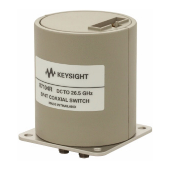
Introduction General Information Keysight 87104P/Q/R SP4T and 87106P/Q/R SP6T terminated switches provide the life and reliability required for automated test and measurement and signal monitoring and routing applications. These switches can be used in various applications as they are available in multiple frequency ranges, up to 26.5 GHz. Figure 1-1 Keysight 8710x Low PIM Coaxial Multiport Switches Innovative design and careful process control create switches that meet the requirements for highly repeatable switching elements in... -
Page 11: Key Features
Introduction Table 1-1 List of Keysight 8710x Low PIM Coaxial Multiport Switches Model number Frequency range Configuration 87104P DC to 4 GHz SP4T 87104Q DC to 20 GHz SP4T 87104R DC to 26.5 GHz SP4T 87106P DC to 4 GHz SP6T 87106Q DC to 20 GHz... - Page 12 Introduction This page is intentionally left blank. Keysight 8710x Operating and Service Manual...
-
Page 13: Switch Configuration
Keysight 8710x Low PIM Coaxial Multiport Switches Operating and Service Manual Switch Configuration Driving the Switch 12 Standard Drive 13 TTL Drive (Option T24) 14 Electronic Position Indicators 15 This chapter provides you information on how to drive the switches using standard drive and TTL drive. Also included is the configuration to utilize the function of the position indicator. -
Page 14: Driving The Switch
Switch Configuration Driving the Switch Each RF path can be closed by applying ground (TTL “High” for Option T24) to the corresponding “drive” pin. In general, all other RF paths are simultaneously opened by internal logic. See Figure 2-1 drive connection diagrams. Drive Sense Drive... -
Page 15: Standard Drive
Switch Configuration Standard Drive 1 Connect pin 1 to supply voltage (+20 Vdc to +32 Vdc) and pin 15 to ground. Pin 15 must always be connected to ground to enable the electronic N O T E position-indicating circuitry and drive logic circuitry. If pin 15 is not connected to power supply ground, catastrophic failure will C A U T I O N occur. -
Page 16: Ttl Drive (Option T24)
Switch Configuration TTL Drive (Option T24) 1 Connect pin 1 to supply voltage (+20 Vdc to +32 Vdc) and pin 15 to ground. Pin 15 must always be connected to ground to enable the electronic N O T E position-indicating circuitry and drive logic circuitry. In addition to the quiescent current supplying the electronic position-sensing circuitry, the drive current flows out of pin 15 (during switching) on TTL drive switches (option T24). -
Page 17: Electronic Position Indicators
Switch Configuration Electronic Position Indicators The electronic position indicators consist of optically isolated, solid state relays which are driven by photo-electric sensors coupled to the mechanical position of the RF path’s moving elements (see Figure 2-2). The circuitry consists of a common which can be connected to an output corresponding to each RF path. - Page 18 Switch Configuration This page is intentionally left blank. Keysight 8710x Operating and Service Manual...
-
Page 19: Specifications
Keysight 8710x Low PIM Coaxial Multiport Switches Operating and Service Manual Specifications General Specifications 18 Supplemental specifications (cold switching) 18 RF Specifications 20 Indicator Specifications 21 Switch Drive Specifications 22 TTL drive (option T24) 22 Environmental Specifications 23 Physical Specifications 24 This chapter provides the specifications of the switches. -
Page 20: General Specifications
Specifications General Specifications Keysight model number 87104P/Q/R and 87106P/Q/R 1 watt average into 50 Ω internal loads Maximum power rating Hot switching 1 watt CW 50 W peak, 10 μs max pulse width, not to exceed 1 W average. Cold switching “Supplemental specifications (cold switching)”... - Page 21 Specifications Figure 3-3 Maximum incident power (cold switching) vs. frequency VSWR (:1) Figure 3-4 Power derating factor vs. VSWR Keysight 8710x Operating and Service Manual...
-
Page 22: Rf Specifications
Specifications RF Specifications Keysight model number 87104P and 87106P 87104Q and 87106Q Frequency range DC to 4 GHz DC to 20 GHz Insertion loss (dB) 0.015f + 0.3 0.015f + 0.3 Isolation (dB) > 100 > 100 (DC to 12 GHz) >... -
Page 23: Indicator Specifications
Specifications Keysight model number 87104R and 87106R Frequency range DC to 26.5 GHz Insertion loss (dB) 0.015f + 0.3 Isolation (dB) > 100 (DC to 12 GHz) > 80 (12 to 15 GHz) > 70 (15 to 20 GHz) > 65 (20 to 26.5 GHz) <... -
Page 24: Switch Drive Specifications
Specifications Switch Drive Specifications Parameter Unit Supply voltage, Vcc † Supply current, Icc Supply current (quiescent) * Switching condition: pulse width ≥ 15 ms (Vcc = 24 VDC). † Closing one RF path requires 200 mA. Add 200 mA for each additional RF path closed or opened. -
Page 25: Environmental Specifications
Specifications Environmental Specifications The Keysight 8710x low PIM coaxial multiport switches are designed to fully comply with Keysight’s product operating environmental specifications. Parameter Specification Temperature –25 °C to 75 °C • Operating –55 °C to 85 °C • Storage –50 °C to 150 °C, 10 cycles •... -
Page 26: Physical Specifications
Specifications Physical Specifications Parameter Specification Dimensions Figure 3-6 Net weight, kg (lb) 0.370 (0.82) Figure 3-6 Dimensions of Keysight 8710x Low PIM Coaxial Multiport Switches Keysight 8710x Operating and Service Manual... -
Page 27: Installation And Verification
Keysight 8710x Low PIM Coaxial Multiport Switches Operating and Service Manual Installation and Verification Installation 26 Initial inspection 26 Operating and Service Instructions 27 Operator’s check 27 Performance test 28 Service instructions 28 This chapter provides you installation information and simple verification steps of the switches. -
Page 28: Installation
Installation and Verification Installation Initial inspection 1 Inspect the shipping container for damage. If the shipping container or cushioning material is damaged, it should be kept until the contents of the shipment have been checked for completeness and the instrument has been checked both mechanically and electrically. -
Page 29: Operating And Service Instructions
Installation and Verification Operating and Service Instructions Operator’s check The operator’s check is supplied to allow the operator to make a quick check on the coaxial multiport switches prior to use or if a failure is suspected. ESD exceeding the level specified in “Environmental Specifications”... -
Page 30: Performance Test
Installation and Verification Quick check procedure 1 Connect the common port of the switch to Port 1 of the network analyzer and one of the outer RF ports to Port 2 of the network analyzer as illustrated in Figure 4-7. 2 For standard drive, apply ground to the corresponding “drive”... - Page 31 Installation and Verification Maintenance The connectors, particularly the connector faces, must be kept clean. For instructions on connecting and care of your connectors, refer to the Microwave Connector Care Quick Reference Card (08510-90360). Replacement units Replacement unit Part number Low PIM switch, SP4T, DC - 4 GHz, terminated with Option 100, 024 87104-60066 Low PIM switch, SP4T, DC - 4 GHz, terminated with Option 100, T24 87104-60067...
- Page 32 Installation and Verification Replacement unit Part number Low PIM switch, SP6T, DC - 26.5 GHz, terminated with Option 100, 024 87106-60102 Low PIM switch, SP6T, DC - 26.5 GHz, terminated with Option 100, T24 87106-60103 Low PIM switch, SP6T, DC - 26.5 GHz, terminated with Option 161, 024 87106-60104 Low PIM switch, SP6T, DC - 26.5 GHz, terminated with Option 161, T24 87106-60105...
- Page 33 This information is subject to change without notice. © Keysight Technologies 2014 Edition 2, October 2014 *87104-80017* 87104-80017 www.keysight.com...
Need help?
Do you have a question about the 8710 Series and is the answer not in the manual?
Questions and answers