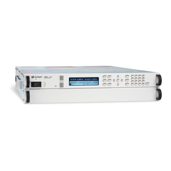
Keysight Technologies E4360 Series User Manual
Modular solar array simulator
Hide thumbs
Also See for E4360 Series:
- Service manual (75 pages) ,
- Service manual (75 pages) ,
- User manual (118 pages)
Table of Contents
Advertisement
Advertisement
Table of Contents

Related Manuals for Keysight Technologies E4360 Series


Summary of Contents for Keysight Technologies E4360 Series
- Page 1 Keysight Technologies Series E4360 Modular Solar Array Simulator User’s Guide...
- Page 3 Legal Notices U.S. Government Rights Warranty © Keysight Technologies 2008 – 2018 The Software is “commercial computer THE MATERIAL CONTAINED IN THIS software,” as defined by Federal Acquisition DOCUMENT IS PROVIDED “AS IS,” AND IS No part of this document may be Regulation (“FAR”) 2.101.
- Page 4 Do Not Operate in an Safety Symbols Safety Notices Explosive Atmosphere Direct current The following general safety Do not operate the instrument in the precautions must be observed during Alternating current presence of flammable gases or all phases of operation of this fumes.
- Page 5 Programmer’s Reference Guide available at http://www.keysight.com/find/E4360 under Technical Support NOTE You can contact Keysight Technologies at one of the following telephone numbers for warranty, service, or technical support information. In the United States: (800) 829-4444 In Europe: 31 20 547 2111...
-
Page 6: Table Of Contents
Contents 1 - Quick Reference Information .................. 9 The Keysight E4360 SAS – At a Glance........10 The Front Panel - At a Glance ............ 12 The Rear Panel – At a Glance ............. 12 Front Panel Display – At a Glance ..........13 Front Panel Keys –... - Page 7 Peak Power Tracker Application..........91 Exponential Model Equations*............ 92 Series Switching Regulation ............93 Shunt Switching Regulation ............93 B - Digital Port Functions.................... 95 Digital Control Port..............96 C - SCPI Commands....................103 SCPI Command Summary ............104 D - Grouping/Compatibility ..................109 Output Grouping...............
-
Page 9: Quick Reference Information
Quick Reference Information The Keysight E4360 SAS – At a Glance........10 The Front Panel - At a Glance ............ 12 The Rear Panel – At a Glance ............. 12 Front Panel Display – At a Glance ..........13 Front Panel Keys – At a Glance ..........15 Front Panel Menu Reference ............ -
Page 10: The Keysight E4360 Sas - At A Glance
General Information The Keysight E4360 SAS – At a Glance The Keysight E4360 Modular Solar Array Simulator (SAS) is a DC current source with very low output capacitance that simulates the output characteristics of a solar array. It is capable of simulating the I-V curve of a solar array under different conditions such as temperature and age. - Page 11 General Information Output Features Low output capacitance Low output capacitance allows faster output response time in constant current operation. Fast up/down voltage Less than 8 millisecond response time from 10% to 90% of the programming output rating. Fast I-V curve change Fast I-V curve change in both SAS mode and Table mode.
-
Page 12: The Front Panel - At A Glance
General Information The Front Panel - At a Glance Di splay N avigation keys Ou tput keys Turns off after 1 hour of inactivity. Move the cursor to a menu item. Turn the outputs on or off. Press any key to restore the display. Select the highlighted menu item. -
Page 13: The Rear Panel - At A Glance
General Information The Rear Panel – At a Glance 8-p in digital control LAN connector con nector 10/100 Base-T Connector function is Green LED = activity. user-configurable. GPIB connector USB connector Red LED = link integrity. 1 2 3 4 5 6 7 5-p in output 5-p in analog C h assis ground... -
Page 14: Front Panel Display - At A Glance
General Information Front Panel Display – At a Glance Single-channel view Voltage measurement Current measurement Press the Meter key to toggle between views Operating status Voltage and Interface status (CV = constant voltage) current settings (IO = activity on interface) Multiple-channel view Voltage and Current measurements Press the Meter key... -
Page 15: Front Panel Keys - At A Glance
General Information Front Panel Keys – At a Glance System keys Meter returns the display to metering mode. Meter Menu Menu accesses the command menu. Channel selects or highlights a channel to control. Back Channel Back backs out of a menu without activating any changes. Help accesses information about the displayed menu control. -
Page 16: Front Panel Menu Reference
General Information Front Panel Menu Reference NOTE Menu commands that are grayed-out are password protected. Menu Command Control Description Output Fixed Voltage Programs the output voltage in Fixed mode Current Programs the output current in Fixed mode Curve Programs the SAS curve parameters (Vmp, Voc, Imp, Isc). Source Selects the source of the curve parameters (Immediate, List) Table... - Page 17 General Information Menu Command Control Description System DigPort Pin3 Function Specifies pin function: DigIn, DigIO, TrigIn, TrigOut, InhibitIn. Polarity Specifies pin polarity: Positive, Negative Trig Out Specifies the output trigger source. Acq, Tran, Dwel, Dlog Pin4 Function Specifies pin function: DigIn, DigIO, TrigIn, TrigOut, OnC, OffC. Polarity Specifies pin polarity: Positive, Negative Trig Out...
-
Page 19: Installation
Installation General Information..............20 Inspecting the Unit ..............21 Installing the Unit ............... 21 AC Line Connection ..............26 Rear Panel Connectors ............... 26 Load Connections ............... 28 Remote Voltage Sensing ............31 Connecting Outputs in Parallel ..........33 Connecting Outputs in Series............. 37 Analog Current Control .............. -
Page 20: General Information
Installation General Information Models Model Description E4360A SAS mainframe – without output modules E4361A 65 V, 8.5 A, 510 W module E4362A 130 V, 5 A, 600 W module E4367A E4360A + 2 – E4361A E4368A E4360A + 2 – E4362A E4369A Filler module –... -
Page 21: Inspecting The Unit
Installation Inspecting the Unit When you receive your Keysight E4360 SAS, inspect it for any obvious damage that may have occurred during shipment. If there is damage, notify the shipping carrier and the nearest Keysight Sales and Support Office immediately. Refer to www.keysight.com/find/assist. - Page 22 Installation Channel Number The channel number of an output module is determined by the location of that module in the mainframe. When viewed from the rear, the module next to the GPIB connector is always channel one. The module next to channel one is always channel two. If there is only one module, it must be installed next to the GPIB connector with a filler module installed in the remaining open space to ensure proper airflow for cooling.
- Page 23 Installation Ste p 2. If a filler module is installed in the mainframe, first remove the filler module. Remove the two fastening screws at either end of the module. Ste p 3. To install an output module, align the module over the alignment pins, and push it down onto the mainframe connector.
- Page 24 Installation Ste p 5. Attach the front ears to the front of the instrument rack using the dress 10-32 screws (5) provided. Ste p 6. This is optional. Insert a plain 10-32 screw (6) through the slot of the rear ear and extender support. Attach it with a clip-nut. Note that this will prevent the unit from being slid out of the front of the rack.
- Page 25 Installation Bench Installation Do not block the air intake and exhaust at the sides, or the exhaust at CAUTION the rear of the unit. Refer to the outline diagram in Appendix A. Minimum clearances for bench operation are 2 inches (51 mm) along the sides and back.
-
Page 26: Ac Line Connection
Installation AC Line Connection FIRE HAZARD Use only the power cord that was supplied with your WARNING instrument. Using other types of power cords may cause overheating of the power cord, resulting in fire. SHOCK HAZARD The power cord provides a chassis ground through a third conductor. - Page 27 Installation It is good engineering practice to twist the sense wire pairs as well as the load wire pairs. Insert wires Tighten screws Diode terminal adds diode in series with + output + sense connection + output terminal − − output terminal −s −...
-
Page 28: Load Connections
Installation Digital Connector This connector, which is on the rear panel, is for connecting digital I/O, fault/inhibit, trigger, or output couple signals. The connector accepts wires sizes from AWG 16 to AWG 28. Refer to Appendix B for more information about digital connections. It is good engineering practice to twist or shield all signal wires to and from the digital connector. - Page 29 Installation Multiple Outputs If you are using local sensing and are connecting multiple outputs to one load, connect each output to the load using separate connecting wires. Keep each pair of wires as short as possible and twist or bundle them to reduce lead inductance and noise pickup.
- Page 30 Installation Output Isolation and Grounding The positive output terminal should NOT be connected to ground in CAUTION applications where the output voltage is repeatedly and rapidly changing as is the case in a series or shunt regulator application. This can result in overheating and damaging the resistors of internal RC networks that are connected to ground.
-
Page 31: Remote Voltage Sensing
Installation Remote Voltage Sensing Remote sensing improves the voltage regulation at the load by monitoring the voltage there instead of at the output terminals. This allows the unit to automatically compensate for the voltage drop in the load leads as well as accurately read back the voltage directly at the load. - Page 32 Installation Because the sense leads are also part of the unit's feedback path, keep the resistance of the sense leads low to obtain the best performance. The additional load regulation due to resistance in the sense leads is given by the formula: (total load lead drop) * (total sense lead resistance) Regulation in millivolts = where K = 3 for E4361A;...
-
Page 33: Connecting Outputs In Parallel
Installation Connecting Outputs in Parallel Only connect output modules in parallel that have identical model WARNING numbers and options Output channels can be paralleled to obtain increased output current. There are two ways to implement this: direct-parallel and auto-parallel. Parallel Method Description Connections Direct-Parallel... - Page 34 Installation Twist or E4360A E4360A output 2 output 1 output 2 output 1 bundle wire pair Jumpers installed on all outputs for local sensing R Load As a convenience, you can group the two channels that are paralleled in a single mainframe to make them look, from a programming point of view, like a single channel.
- Page 35 Installation Auto-Parallel Connections For the firmware to correctly control the paralleled output channels, NOTE you must specify that the output channels are connected in auto- parallel, and which channel is configured as the master and which channels are configured as followers. Refer to chapter 4 under “Configuring Paralleled Outputs”.
- Page 36 Installation As shown in the following table, the capacitor values required for the two compensation methods depend on the number of follower outputs that are paralleled. # of Follower outputs Output capacitor (5a) RC values (5b) 3.3 µF min. (< 6Ω ESR) 0.47 µF/68 Ω...
-
Page 37: Connecting Outputs In Series
Installation Parallel Programming Cautions To avoid possible tripping of the crowbar SCR, do not turn parallel CAUTION outputs off while they are operating in SAS or Table mode. Program all outputs to Fixed mode and set the voltage to zero before turning them off. -
Page 38: Analog Current Control
Installation If you have questions about connecting outputs in series, contact your local Keysight Sales and Support Office for details. output 2 output 1 Jumpers installed for E4360A local sensing R Load Analog Current Control Analog Current Control only applies in Fixed mode operation, and can CAUTION program a single output. -
Page 39: Getting Started
Getting Started Using the Front Panel Controls ..........40 Using the Front Panel Menu ............42 In Case of Trouble............... 43 Connecting to the Interfaces ............44 This chapter describes how to get started using your SAS. It discusses turning the unit on, using the front panel controls, and navigating the front panel command menu. -
Page 40: Using The Front Panel Controls
Getting Started Using the Front Panel Controls Turning the Unit On After you have connected the line cord, turn the unit on with the front panel LINE switch. The front panel display will light up after a few seconds. When the front panel display appears, you can use the front panel controls to enter voltage and current values. - Page 41 Getting Started 3 Entering a Current Setting Method 1 – Use the Navigation and Arrow Keys Navigation Use the left and right navigation keys to navigate to the setting that Keys you wish to change. In the display below, channel 1’s current setting is selected.
-
Page 42: Using The Front Panel Menu
Getting Started Using the Front Panel Menu The front panel command menu lets you access most of the SAS functions. The actual function controls are located at the lowest menu level. Briefly: Press the Me nu key to access the command menu. ... -
Page 43: In Case Of Trouble
Getting Started 3 The command menu is now at the function control level. This is the lowest level in this path. Use the navigation keys to highlight the OVP Level control as shown below. Enter the desired over-voltage level using the numeric keypad. Then press Enter. -
Page 44: Connecting To The Interfaces
GPIB Interface For detailed information about GPIB interface connections, refer to the NOTE Keysight Technologies USB/LAN/GPIB Interfaces Connectivity Guide, located on the Automation-Ready CD that is shipped with your product. The following steps will help you quickly get started connecting your instrument to the General Purpose Interface Bus (GPIB). - Page 45 USB Interface For detailed information about USB interface connections, refer to the NOTE Keysight Technologies USB/LAN/GPIB Interfaces Connectivity Guide, located on the Automation-Ready CD that is shipped with your product. The following steps will help you quickly get started connecting your USB-enabled instrument to the Universal Serial Bus (USB).
- Page 46 IP address. If this does not work, refer to the chapter on “Troubleshooting NOTE Guidelines” in the Keysight Technologies USB/LAN/GPIB Interfaces Connectivity Guide. You can now use Interactive IO within the Connection Expert to communicate with your instrument, or you can program your instrument using the various programming environments.
- Page 47 If the instrument cannot be found, add the instrument using the instrument’s hostname or IP address. If this does not work, refer to the chapter on “Troubleshooting Guidelines” NOTE in the Keysight Technologies USB/LAN/GPIB Interfaces Connectivity Guide. Series E4360 User’s Guide...
- Page 48 Getting Started You can now use Interactive IO within the Connection Expert to communicate with your instrument, or you can program your instrument using the various programming environments. You can also use the Web browser on your computer to communicate with the instrument as described under “Using the Web Server”...
- Page 49 Getting Started 3 IP Address This value is the Internet Protocol (IP) address of the instrument. An IP address is required for all IP and TCP/IP communications with the instrument. An IP Address consists of 4 decimal numbers separated by periods. Each decimal number ranges from 0 through 255. Subnet Mask This value is used to enable the instrument to determine if a client IP address is on the same local subnet.
- Page 50 Getting Started Select DNS to configure the Domain Name System (DNS) setup of the instrument. DNS is an internet service that translates domain names into IP addresses. It is also needed for the instrument to find and display its hostname assigned by the network. Obtain DNS Select this item to obtain the DNS server address from DHCP.
- Page 51 Getting Started 3 Using the Web Server Your SAS has a built-in Web server that lets you control it directly from an internet browser on your computer. With the Web server, you can access the front panel control functions including the LAN configuration parameters.
- Page 52 Getting Started Click on the Browser Web Control button in the navigation bar on the left to begin controlling your instrument. All of the Browser Web controls are located in the drop-down menus that appear on the top of the page. These controls are very similar to the front panel menus of the instrument.
- Page 53 Getting Started 3 Using Telnet In an MS-DOS Command Prompt box type: telnet hostname 5024 where hostname is the E4360 hostname or IP address, and 5024 is the instrument’s telnet port. You should get a Telnet session box with a title indicating that you are connected to the SAS.
-
Page 55: Using The Solar Array Simulator
Using the Solar Array Simulator Operating in Fixed Mode ............56 Making Measurements ............... 57 Using the Protection Functions ..........61 Configuring Paralleled Outputs ..........63 Operating in SAS Mode .............. 64 Programming Curve Lists ............67 Operating in Table Mode ............72 Data Logging Measurements ............. -
Page 56: Operating In Fixed Mode
Using the Solar Array Simulator Operating in Fixed Mode At power turn on, with *RST, or when executing a Device Clear, the operating state of the SAS is set to Fixed mode. As shown in the following figure, the Fixed mode output characteristic is similar to that of a standard power supply, except that the output capacitance is <100 nF on the Keysight E4361A, and <50 nF on the Keysight E4362A. -
Page 57: Making Measurements
Using the Solar Array Simulator Set the Output Voltage Front Panel: SCPI Command: Press the Voltage key. To set output 1 to 50 V: Enter a value and press Select. VOLT 50,(@1) To set all outputs to 60 V: VOLT 60,(@1,2) Set the Output Current Front Panel: SCPI Command:... - Page 58 Using the Solar Array Simulator To return both values of either a voltage or current measurement: Front Panel: SCPI Command: Select the Meter key. Measure the output voltage or current: MEAS:VOLT? (@1,2) Then Fetch the other parameter: FETC:CURR? (@1,2) You can use the measurement trigger system to synchronize the acquisition of measurements with a bus trigger, a transient trigger from another channel, or an external trigger signal.
- Page 59 Using the Solar Array Simulator Select the Measurement Trigger Source An immediate trigger command over the bus will generate an NOTE immediate trigger regardless of the trigger source. Unless you are using the TRIG:ACQ:IMM command to trigger the measurement, select a trigger source from the following: Selects GPIB device trigger, *TRG, or <GET>...
- Page 60 Using the Solar Array Simulator Trigger the Measurement You can immediately trigger the measurement as follows: Front Panel: SCPI Command: Not available To trigger a measurement on output 1: TRIG:ACQ (@1) If the trigger source is BUS, you can send *TRG or an IEEE-488 <get>. As previously discussed, a trigger can also be generated by another output channel or an input pin on the digital port connector.
-
Page 61: Using The Protection Functions
Using the Solar Array Simulator Using the Protection Functions Each output has independent protection functions. A front panel status indicator will turn on when a protection function has been set. Protection functions are latching, which means that they must be cleared once they have been set. - Page 62 Using the Solar Array Simulator Front Panel: SCPI Command: To enable protection Coupling: Select Protect\Coupling. Check the Enable Coupling box and OUTP:PROT:COUP ON press Select. Clear Output Protection Functions If an over-voltage, over-current, over-temperature, over-switching, power-fail condition, protection condition, or inhibit signal occurs, the SAS turns off the affected output channel.
-
Page 63: Configuring Paralleled Outputs
Using the Solar Array Simulator Configuring Paralleled Outputs Direct-Parallel or Auto-Parallel Specify whether an output channel is connected in direct-parallel or auto-parallel. Refer to chapter 2 for connection information. Front Panel: SCPI Command: Select To specify auto-parallel: System\Groups\Parallel. SYST:GRO:PAR AUTO,(@1) To specify direct-parallel: Select either Direct or Auto. -
Page 64: Operating In Sas Mode
Using the Solar Array Simulator Operating in SAS Mode SAS mode uses an exponential model to approximate the I-V curve as illustrated in the following figure. It is programmed in terms of its open circuit voltage (Voc), short circuit current (Isc), maximum voltage point (Vmp), and maximum current point (Imp) at the approximate peak power point (see Appendix A for model equations). - Page 65 Using the Solar Array Simulator The resolution setting applies to this channel whenever a curve is programmed in SAS mode or a Table is loaded in Table mode. The large table (4096 points) will give a smoother I-V curve but takes much longer to update.
- Page 66 Using the Solar Array Simulator Program the Curve Program the SAS curve parameters as follows: Front Panel: SCPI Command: Select Output\SAS\Curve. To program Vmp, Voc, Imp, and Isc on the same program line: Enter the curve parameters in the Vmp, Voc, Imp, and Isc CURR:SAS:ISC 5,(@1);...
-
Page 67: Programming Curve Lists
Using the Solar Array Simulator Parameter E4361A Output E4362A Output Module Module Pmp (maximum power) ≤ 510 W ≤ 600 W Voc (voltage, open-circuit) ≤ 65 V ≤ 130 V Isc (current, short circuit) 8.5 A Vmp (voltage, maximum power) <... - Page 68 Using the Solar Array Simulator ABOR:TRAN INIT:CONT OFF IDLE state *RST *RCL INIT:TRAN TRIG:TRAN:SOUR INIT:CONT ON INITiated state (Pin<3-7>) Transient Trigger TRAN<1-2> DWEL<1-2> Output changes TRIG:TRAN:IMM Dwell-paced Trigger-paced List count complete? If you need the curve lists to closely follow external events, the lists can be paced by external trigger signals.
- Page 69 Using the Solar Array Simulator Program the List The following procedure shows how to program a list of I-V curves. Ste p 1. Set the SAS mode to List. Front Panel: SCPI Command: To program output 1, use Select Output\SAS\Source. Set the SAS mode to List.
- Page 70 Using the Solar Array Simulator Ste p 5. Specify how you want the list to terminate. You can either return to the settings in effect before the list started, or remain at the settings of the last list curve (step). Front Panel: SCPI Command: To return to the pre-list settings:...
- Page 71 Using the Solar Array Simulator Initiate the Trigger System and Provide a Trigger First, make sure that the selected output is enabled. Front Panel: SCPI Command: To enable output 1: Select the correct channel. Press the On/Off key. OUTP ON,(@1) At turn-on, the trigger system is in the Idle state, in which all triggers are ignored.
-
Page 72: Operating In Table Mode
Using the Solar Array Simulator Operating in Table Mode Output synchronization is NOT provided in Table mode; this means that NOTE the output will activate a table as soon as the command is received. You cannot synchronize table changes between outputs or mainframes. There is also no list support for table changes. - Page 73 Using the Solar Array Simulator Select the Table Select a table as follows: Front Panel: SCPI Command: To select a table on output 1: Select Output\Table\Select Table. CURR:TABL:NAME name,(@1) Select a table from the list on the left and press Select. Enable Table Mode To enable Table mode: Front Panel:...
- Page 74 Using the Solar Array Simulator Program the Table If a table does not exist, you must program a new table. Programming a table consists of entering voltage data and current data to create the desired number of I-V coordinate-pairs. The number of voltage values must match the number of current values.
- Page 75 Using the Solar Array Simulator Table Offsets A new table can be generated by applying a limited voltage or current offset to an existing table. This can be helpful in simulating temperature, angular, rotational, or aging changes. Offset values are non-cumulative, they can be either positive or negative, and can be applied to any table.
-
Page 76: Data Logging Measurements
Using the Solar Array Simulator Table Resolution When operating in Table mode, the voltage/current values are converted into a DAC table used by the instrument to control the output. You have a choice in the size of this DAC table to optimize your application for either better table resolution or faster update speed. - Page 77 Using the Solar Array Simulator Select the Pacing and Time Interval Data capture can be trigger-paced or a time-paced. Specify TRIGger to select trigger-paced data capture, or TIMer to select time-paced data capture. With time-paced data capture, you must also specify the time interval.
- Page 78 Using the Solar Array Simulator Initiate the Data Logger When the SAS is turned on, the data logger is in the Idle state. In this state, the data logger is disabled, ignoring all triggers. The INITiate command enables the data logger to receive triggers. This resets the datalog buffer and enables data logging on subsequent triggers.
- Page 79 Using the Solar Array Simulator Format and Fetch the Measurements Data transferring can be accomplished in the following formats: ASCII - Numeric data is transferred as ASCII bytes in <NR1>, <NR2>, or <NR3> format as appropriate. The numbers are separated by commas. REAL - Data is transferred in a definite-length block as floating point numbers of 32 bits.
-
Page 80: System-Related Operations
Using the Solar Array Simulator System-Related Operations Grouped Channels Output channels can be configured or “grouped” to create a single output with higher current and power capability. Refer to Appendix D for more information. Instrument State Storage The SAS has two storage locations in non-volatile memory to store instrument states. - Page 81 Using the Solar Array Simulator Front Panel Keys Lockout You can lock the front panel keys to prevent unwanted control of the instrument from the front panel. This is the most secure way of locking the front panel keys because you need a password to unlock the front panel.
- Page 82 Using the Solar Array Simulator Front Panel Display Screen Saver The SAS has a front panel screen saver that significantly increases the life of the LCD display by turning it off during periods of inactivity. As shipped from the factory, the screen saver comes on one hour after activity on the front panel or interface has ceased.
- Page 83 Using the Solar Array Simulator Administration Functions Accessing the Administration Functions The Administration menu is password-protected. To log into the Administration menu: Front Panel: SCPI Command: Select System\Admin\Login Not Available. If a password is required, enter it in the Password field and press Enter. If the Password field shows 0, simply press Enter.
- Page 84 Using the Solar Array Simulator Front Panel: SCPI Command: Log into the Admin menu as previously Not Available. described. Then select USB. Check Enable USB to enable the USB interface. Un-check this box to disable the USB. Restoring the Non-volatile Factory Settings Remote interface and certain front panel control settings are stored in non-volatile memory (refer to the following table).
- Page 85 Using the Solar Array Simulator Sanitizing Table Memory The sanitize operation only affects the instrument’s table memory. Sanitizing first writes a 0, then a 1, and then random values to all memory locations. It then performs a full chip erase on the instrument’s flash memory device.
-
Page 87: A - Specifications And Application Information
Appendix A Specifications and Application Information Keysight E4360A SAS Mainframe..........88 Outline Diagram ................. 90 Peak Power Tracker Application..........91 Exponential Model Equations*............ 92 Series Switching Regulation ............93 Shunt Switching Regulation ............93 Supplemental Characteristics are not warranted but are descriptions of performance determined either by design or type testing. -
Page 88: Keysight E4360A Sas Mainframe
Appendix A Specifications and Application Information Keysight E4360A SAS Mainframe Supplemental Characteristics Parameter E4360A Command Processing Time ≤ 1 ms from receipt of command to start of output change Savable States Memory locations: 2 ( 0 and 1) Pre-stored state: Protection Response Characteristics 5 µs from receipt of inhibit to start of shutdown INH input:... - Page 89 Specifications and Application Information Appendix A Supplemental Characteristics (continued) Parameter E4360A Regulatory Compliance EMC: Complies with European EMC Directive for test and measurement products. ● IEC/EN 61326-1 ● CISPR 11, Group 1, class A ● AS/NZS CISPR 11 ● ICES/NMB-001 Complies with Australian standard and carries C-Tick mark.
-
Page 90: Outline Diagram
Appendix A Specifications and Application Information Outline Diagram 598.0 mm 23.54" 608.5 mm 23.96" TOP OF UNIT 25.4 mm 1.00" 88.1 mm 432.5 mm 3.5" 17.03" 44.45 mm 482.6 mm 1.75 in. 19.00" FRONT FRONT J01 = AIRFLOW 425.5 mm 16.75"... -
Page 91: Peak Power Tracker Application
Specifications and Application Information Appendix A Peak Power Tracker Application The peak power tracker is a customer-provided application. In this application, the load is constantly searching for the maximum power point of the I-V curve. To achieve this, the peak power tracker sweeps around the peak power point. -
Page 92: Exponential Model Equations
Appendix A Specifications and Application Information Exponential Model Equations* The following equations describe the solar array simulator exponential model using the parameters Rs, N, and a, which are defined as functions of the four input parameters. Note that these equations tend to be most accurate for curves that are somewhat rectangular.** Figure A-2 indicates the potential range of Pmp error percent due to the modeling equation. -
Page 93: Series Switching Regulation
Specifications and Application Information Appendix A Series Switching Regulation Outputs must be connected in direct or in auto-parallel as explained in chapter 2. In this application, regulation is achieved by controlling the duty cycle of a series FET, which can be operated at frequencies up to 50kHz. -
Page 95: B - Digital Port Functions
Appendix B Digital Port Functions Digital Control Port..............96 A Digital Control Port consisting of seven I/O pins is provided to access various control functions. Each pin is user-configurable. The following control functions are available for the I/O pins: Bi-directional Digital I/O ... -
Page 96: Digital Control Port
Appendix B Digital Port Functions Digital Control Port An 8-pin connector and a quick-disconnect connector plug are provided on each instrument for accessing the digital control port functions. TIGHTEN SCREWS INSERT WIRES Input/Output Signal Common signals The digital control connector accepts wires sizes from AWG 14 to AWG 30. - Page 97 Digital Port Functions Appendix B Bi-directional Digital I/O Each of the seven pins can be configured as general-purpose bi- directional digital inputs and outputs. The polarity of the pins can also be configured. Pin 8 is the signal common for the digital I/O pins. Data is programmed according to the following bit assignments: (msb) (lsb)
- Page 98 Appendix B Digital Port Functions Digital Input Each of the seven pins can be configured as digital input only. The polarity of the pins can also be configured. Pin 8 is the signal common for the digital input pins. The pin status reflects the true condition of the external signal that is applied to the pin.
- Page 99 Digital Port Functions Appendix B Front Panel: SCPI Command: Select To select the trigger output System\IO\DigPort\Pin<n>, function for pin 1: where <n> is the pin number. DIG:PIN1:FUNC TOUT To select the trigger input Select Function, then either function for pin 2: Trigger In or Trigger Out.
- Page 100 Appendix B Digital Port Functions Front Panel: SCPI Command: Select To configure the Fault function: System\IO\DigPort\Pin1. DIG:PIN1:FUNC FAUL To select the fault output polarity: Select Function, then Fault Out. DIG:PIN1:POL <pol> Go back one level, select Polarity, then either Positive or Negative.
- Page 101 Digital Port Functions Appendix B As shown in the previous figure, when the Fault outputs and Inhibit inputs of several mainframes are daisy-chained, an internal fault condition in one of the mainframes will disable all of them without intervention by either the controller or external circuitry. You must select the sa me polarity (either positive or negative) for all FLT and INH pins in the daisy chain.
- Page 102 Appendix B Digital Port Functions Output coupling must be enabled on all mainframes that will have one or more of their outputs coupled. Front Panel: SCPI Command: In the front panel menu, select To enable, send: Output\Couple. OUTP:COUP ON Check the box labeled “Enable”. To disable, send: To disable, un-check the box.
-
Page 103: C - Scpi Commands
Appendix C SCPI Commands SCPI Command Summary ............104 This appendix gives the list of SCPI commands that are used to program the Keysight E4360A Solar Array Simulator. For complete details on programming the instrument using SCPI NOTE commands, refer to the Keysight 14360A Programmer’s Reference Guide available at http://www.keysight.com/find/E4360 under Technical... -
Page 104: Scpi Command Summary
Appendix C SCPI Commands SCPI Command Summary Some [optional] commands have been included for clarity. All settings NOTE commands have a corresponding query. Not all commands apply to all models. SCPI Command Description ABORt [:TRANsient] [(@chanlist)] Resets the transient trigger system to the Idle state :ACQuire [(@chanlist)] Resets the measurement trigger system to the Idle state :DLOG [(@chanlist)]... - Page 105 SCPI Commands Appendix C SCPI Command Description MEMory :COPY:TABLe <CPD> Copies the selected table to non-volatile memory :DELete [:NAME] <CPD> Deletes the specified table in volatile/non-volatile memory :ALL Deletes all tables in volatile and non-volatile memory :TABLe :CATalog? Returns all table names in volatile/non-volatile memory :CURRent [:MAGnitude] <NRf>{,<NRf>} Programs a list of current points for a new table...
- Page 106 Appendix C SCPI Commands SCPI Command Description :PROTection [:LEVel] <NRf+> [,(@chanlist)] Sets the over-current protection level :SAS :IMP <NRf> [,(@chanlist)] Sets the current at the peak power point of the curve :ISC <NRf> [,(@chanlist)] Sets the short-circuit current :MODE IMMediate | LIST [,(@chanlist)] Selects the source of the curve parameters :SLIMit :HIGH <NRf+>...
- Page 107 SCPI Commands Appendix C SCPI Command Description :PROTection [:LEVel] <NRf>, (@chanlist) Sets the over-voltage protection level :SAS :VMP <NRf>, (@chanlist) Sets the voltage at the peak power point of the curve :VOC <NRf>, (@chanlist) Sets the open-circuit voltage :SLIMit :HIGH <NRf+> | MAXimum [,(@chanlist)] Sets the high soft limit for programming the output voltage :TABle :OFFSet <NRf>...
- Page 108 Appendix C SCPI Commands SCPI Command Description :ACQuire [:IMMediate] [(@chanlist) Triggers the measurement immediately :DELay <NRf> [,(@chanlist) Specifies a time delay for the measurement trigger :SOURce BUS | PIN<n> | TRAN<n> [,(@chanlist)] Sets the measurement trigger source :DLOG [:IMMediate] [(@chanlist)] Triggers the datalog immediately :SOURce Sets the datalog trigger source...
-
Page 109: D - Grouping/Compatibility
Appendix D Grouping/Compatibility Output Grouping............... 110 Compatibility ................112 This appendix described output grouping and compares the Keysight E4360 Modular SAS and the earlier version Keysight E4350B/E4351B SAS instruments. -
Page 110: Output Grouping
Appendix D Grouping/Compatibility Output Grouping Almost all instrument functionality is supported by grouped channels, including voltage and current programming, measurements, status, SAS and Table modes. The following conditions apply for grouped channels: When output channels have been grouped, a single programming ... - Page 111 Grouping/Compatibility Appendix D Front Panel: SCPI Command: To specify auto-parallel: Select System\Groups\Parallel. SYST:GRO:PAR AUTO,(@1) To specify direct-parallel: Select either Direct or Auto. SYST:GRO:PAR DIR,(@1) When grouped channels are wired by direct-parallel, each channel is programmed to control its own output current with its internal circuitry. There is no requirement to designate any master or follower channel.
-
Page 112: Compatibility
Appendix D Grouping/Compatibility Other parameters for each paralleled group will require the same settings to be programmed. In Fixed mode, the same voltage level must be programmed to all groups. In SAS mode, the same model parameters or list step must be in effect for each group. If lists are used, each group must get the same list steps and triggering to cause the channels to change steps at the same time. - Page 113 Grouping/Compatibility Appendix D Item E4350B/E4351B E4360A Modular SAS Rack unit dimensions Height, Width, Depth 132.6mm, 425.5mm, 497.8 mm 88.9mm, 432.5mm, 608.5 mm Rack mounting Standard support rails and ears Custom rack mount kit Weight 25 kg 18.6 kg with two modules installed AC input 100, 120, 220, 240 VAC nominal...
- Page 115 Index control port, connector..........96 control socke t ............... 53 +D terminal ..............29 couple protection ............61 current setting ..............41, 57 current offset ..............75 AC line curve list ................. 67 connection..............26 initiate trigger ............71 current restriction ........... 26 programming ............
- Page 116 Index description..............10 private ................. 47 follower site ................46 configure ............63, 111 sockets................ 53 frequency Telnet ................53 400 Hz................. 25 list programming ............67 front panel loads contrast ..............82 capacitive..............30 display................. 14 connections............... 28 keys................15 grounding ..............
- Page 117 Index over-voltage protection screen saver ..............82 setting ................. 42 sense connections............... 31 series switching regulation ........93 shunt switching parallel frequency ..............30 programming cautions .......... 37 shunt switching regulation ........93 password sockets ................53 calibration..............85 soft limits................ 62 changing ..............
- Page 118 This information is subject to change without notice. © Keysight Technologies 2008 - 2018 Edition 8, December 2018 E4360-90001 www.keysight.com...
Need help?
Do you have a question about the E4360 Series and is the answer not in the manual?
Questions and answers