Table of Contents
Advertisement
Quick Links
Advertisement
Table of Contents

Subscribe to Our Youtube Channel
Related Manuals for Keysight Technologies B2200


Summary of Contents for Keysight Technologies B2200
- Page 1 Keysight Technologies B2200 14ch Low Leakage Switch Mainframe User’s Guide...
- Page 2 Notices Copyright Notice U.S. Government Rights Warranty © Keysight Technologies 2004-2015 The Software is “commercial computer soft- THE MATERIAL CONTAINED IN THIS DOCU- ware,” as defined by Federal Acquisition Reg- MENT IS PROVIDED “AS IS,” AND IS SUBJECT No part of this manual may be reproduced in ulation (“FAR”) 2.101.
- Page 3 User’s Guide B2900-9001x xxxx 201x Edition x...
- Page 4 COMPLIANCE WITH GERMAN NOISE REQUIREMENTS This is to declare that this product is in conformance with the German Regulation on Noise Declaration for Machines (Lärmangabe nach der Maschinenlärminformation-Verordnung -3.GSGV Deutschland). • Herstellerbescheinigung GERÄUSCHEMISSION Lpa < 70 dB am Arbeitsplatz normaler Betrieb nach DIN 45635 T.
- Page 5 In addition, it violates safety standards of design, manufacture, and intended use of the instrument. Keysight Technologies assumes no liability for customer’s failure to comply with these requirements.
- Page 6 Instruments that appear damaged or defective should be made inoperative and secured against unintended operation until they can be repaired by qualified service personnel. Return the instrument to a Keysight Technologies sales or service office for services and repair to ensure that safety features are maintained.
- Page 7 Safety Symbols The general definitions of safety symbols used on equipment or in manuals are listed below. Direct current. Alternating current. Earth ground terminal. Protective conductor terminal. For protection against electrical shock in case of a fault. Used with field wiring terminals to indicate the terminal which must be connected to ground before operating equipment.
- Page 8 The CE mark shows that the product complies with all applicable European Directives. The CSA mark is a registered trademark of the Canadian Standards Association. The RCM mark is a registered trademark of the Australian Communications Authority. This signifies compliance with the Australian EMC Framework Regulations under the terms of the Radio communications Act.
- Page 9 Product Stewardship Waste Electrical and Electronic Equipment (WEEE) The crossed out wheeled bin symbol indicates that separate collection for waste electric and electronic equipment (WEEE) is required, as obligated by the EU DIRECTIVE and other National legislation. Please refer to http://keysight.com/go/takeback to understand your Trade in options with Keysight in addition to product takeback instructions.
- Page 10 "Introduction" Describes an overview of the Keysight B2200 series. "Installation" Describes how to install the Keysight B2200 and how to setup the input/output. "Front Panel Operation" Explains the front panel operation and the switch control functions of the Keysight B2200, also provides the reference information of the front panel keys and display.
-
Page 11: Table Of Contents
Installing the B2200 ........ - Page 12 To Initialize B2200........
- Page 13 To Create Compensation Data File ......4-23 Keysight B2200 User’s Guide, Edition 5...
- Page 14 [:ROUTe]:AGND:UNUSED ........5-28 [:ROUTe]:BIAS:CHANnel:DISable:CARD ......5-29 Keysight B2200 User’s Guide, Edition 5...
- Page 15 :SYSTem:PEN ..........5-49 Keysight B2200 User’s Guide, Edition 5...
- Page 16 ......... 6-14 Keysight B2200 User’s Guide, Edition 5...
- Page 17 ........6-28 Keysight B2200 User’s Guide, Edition 5...
- Page 18 Query Errors ..........7-9 B2200 Specific Error Messages ....... . . 7-10 B2200 Channel Related Errors .
-
Page 19: Introduction
Introduction... - Page 20 Introduction This chapter describes the basic functions and features of the B2200A/B2201A ( B2200 series), and consists of the following sections: • B2200 Series • Front Panel • Rear Panel • Switch Modules • Accessories and Options 1- 2 Keysight B2200 User’s Guide, Edition 5...
-
Page 21: B2200 Series
B2200 series is a switching matrix designed for semiconductor dc characteristics measurement applications. The B2200 series has 14 input ports and four card slots for the switch modules (plug-in cards), and can configure a 12, 24, 36, or 48 outputs switching matrix. -
Page 22: Front Panel
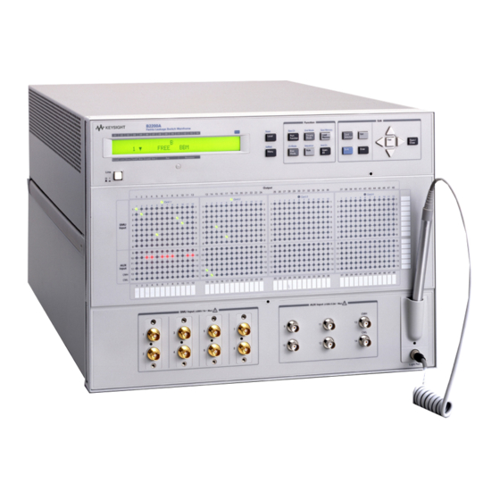
±100 V/0.5 A/100 V. Do not apply an input signal over these limits to the input terminals. If you do, the B2200 will be damaged. If you use a bias source that has current limit capability, set the bias source current limit. - Page 23 Introduction Front Panel Figure 1-1 Front Panel View Keysight B2200 User’s Guide, Edition 5 1- 5...
-
Page 24: Rear Panel
Introduction Rear Panel Rear Panel The B2200 series has four card slots for the switch modules, the GPIB interface and so on. • Card slots For the B2200A mainframe, the B2210A cards are installed. For the B2201A mainframe, the B2211A cards are installed. - Page 25 Introduction Rear Panel Figure 1-2 Rear Panel View Keysight B2200 User’s Guide, Edition 5 1- 7...
-
Page 26: Switch Modules
WARNING Do not touch the force and guard terminals of the output connectors while the B2200 is turned on. Dangerous voltages up to the maximum input voltage may be present at the output connectors. Ne touchez pas les bornes de force et de protection des connecteurs de sortie pendant que le B2200 est en marche. - Page 27 Introduction Switch Modules Figure 1-4 Switch Module Block Diagram Output Input 13 CMH 14 CML Keysight B2200 User’s Guide, Edition 5 1- 9...
-
Page 28: Accessories And Options
Introduction Accessories and Options Accessories and Options B2200 is furnished with the following accessories. • Power cable, 1 ea. • Operation summary sheet, 1 ea. • Software CD, 1 ea. Stores the B2200 VXIplug&play driver. • Moisture-proof and dehumidifying packing kit, 1 set NOTE For the latest system requirements of the VXIplug&play driver, go to... - Page 29 3 m length 16493L GNDU cable (between E5260/E5270 and 16495F/G) 16493L-001 1.5 m length 16493L-002 3 m length 16493L-003 5 m length 16493N GNDU cable for Kelvin connection (between B2200 inputs and E5260/E5270/41501/4142) Keysight B2200 User’s Guide, Edition 5 1- 11...
- Page 30 1.5 m length 16494A-002 3 m length 16494A-003 80 cm length 16494A-005 4 m length 16494B Kelvin triaxial cable (between B2200 inputs and 4142B, between B2210/B2211 outputs and 16495F/G) 16494B-001 1.5 m length 16494B-002 3 m length 16494B-003 80 cm length 16494C...
-
Page 31: Installation
Installation... - Page 32 • Warn workers around the B2200 about dangerous conditions. La tension d'entrée maximale de la B2200 est de ± 200 V. Une tension dangereuse émanant du dispositif Keysight B2200 peut être sortie aux bornes. Les précautions suivantes doivent être obserées contre commotion électrique accidentelle.
-
Page 33: Requirements
Operating Environment • Storage and Shipping Environment Power Requirements The B2200 can operate from any single-phase ac power source supplying 100-240 V (±10 %) at 50/60 Hz. The maximum power consumption is 2 A/200 VA. Power Cable WARNING FIRE HAZARD: Use only the power cable supplied with your instrument. - Page 34 • PN: 8120-8376 • PN: 8121-0564 Option 931 Option 932 • Plug: CNS 10917-2, • Plug: CS 0017, 125 V, 10 A 250 V, 10 A • PN: 8121-1635 • PN: 8121-1638 2- 4 Keysight B2200 User’s Guide, Edition 5...
-
Page 35: Operating Environment
The Keysight B2200 must be packed in the certain packing materials for protection from damage when it is shipped. So it is recommended to retain all packing materials after you unpack the B2200. And use them for repacking the B2200 in the future shipment. -
Page 36: Inspection
The B2200 contains the condensation sensitive electronic parts. The condensation will have a negative impact on the B2200 to operate normally. Do not open the packing materials, and leave the B2200 to acclimate it to the installation environment (temperature and humidity). If it is opened without enough acclimation, the B2200 may damage. -
Page 37: Installing The B2200
2-8. 7. If you have to add or replace the switch module: Turn the B2200 off, remove the power cable, and install the switch module. See To Install the Switch Module on page 2-9 To Install the Blank Panel on page 2-9. -
Page 38: To Set The Gpib Address
Every device on the GPIB bus must have a unique address. If you need to change the GPIB address, turn the B2200 on and perform the following procedure. The new GPIB address is recognized only at power on. The B2200 leaves the factory with the GPIB address set to 22. -
Page 39: To Install The Switch Module
The following procedure explains the module installation and removal. 1. Turn off the B2200, then wait at least 10 seconds before you remove or install a module. 2. Loosen the screws on both the left and right edges of a blank panel or a module attached to the slot you want to install a new module. -
Page 40: Self-Test
It is recommended to perform calibration once a year at least. The following procedure performs the self-test and diagnostics. 1. Turn on the B2200. The controller test will be performed. If the B2200 fails the test, contact your nearest Keysight Technologies Service Center. 2. Press the key and the key in this order. -
Page 41: Output Connections
To Mount Connectors on page 2-18. WARNING Turn off the B2200 and all instruments connected. And do not turn them on until the connection described in this section is completed. If you ignore this warning, you may be exposed to dangerous voltage. -
Page 42: Connector Plates
Ground Ground Connector Plates Connector plates (Table 2-1) are used for the connection between the B2200 outputs and the DUT interface (prober and so on). To connect to the connector plate, use the cable shown in Table 2-2. Table 2-1 Connector Plate Model No. -
Page 43: To Make Connections To Dut Interface
9 (Force) and 10 (Sense) 11 (Force) and 12 (Sense) To Make Connections to DUT Interface This section describes for the connections between the DUT interface and the connectors connected to the B2200 output cables. See Table 2-3. NOTE Low-Noise Coaxial Cable For the extended measurement paths over the connector plate, use low-noise coaxial cable ( part number 8121-1191). - Page 44 Common Common Guard Guard Force Force Triaxial Triaxial Coa xial cable Coa xial cable Common Common connector connector Guard Guard Sense Sense Wire Insulator Insulator Plate Plate 2- 14 Keysight B2200 User’s Guide, Edition 5...
-
Page 45: To Make Interlock Circuit
Guard, and Sense terminals if the Interlock terminal is closed. Une tension dangereuse, une tension de sortie maximale de l'appareil peut apparaître aux bornes Force, Guard et Sense si la borne Interlock est fermée. Keysight B2200 User’s Guide, Edition 5 2- 15... - Page 46 1. Mount LED on your shielding box. For the recommended parts and the dimensions of the LED, see Figure 2-5. 2. Use wire to connect the LED between pin 4 and pin 5 (or 6) of the interlock connector. See Figure 2-3. 2- 16 Keysight B2200 User’s Guide, Edition 5...
- Page 47 3. Connect the BNC cable (furnished with the adapter) between the adapter and the instrument’s interlock connector. • For 4155/4156/E5260/E5270: Connect the 16493J interlock cable between the interlock circuit and the instrument’s interlock connector. You can connect it directly without using any adapter. Keysight B2200 User’s Guide, Edition 5 2- 17...
-
Page 48: To Mount Connectors
To stop the interlock test, select STOP secondary softkey. To Mount Connectors This section provides the information needed to mount connectors for the B2200 output cable connections on the shielding panel. See this section if you do not use the connector plate. - Page 49 Low Noise Coaxial Cable 8121-1191 Table 2-5 Dimensions of Connector Holes Triaxial Connector (in mm) Interlock Connector (in mm) ∅11.3 Kelvin Triaxial Connector (in mm) 10.3 2 − ∅11.3 ∅3.2 2 − M3 x 0.5 Keysight B2200 User’s Guide, Edition 5 2- 19...
-
Page 50: Input Connections
B2200 inputs. Then use the 16493N GNDU cable. This cable requires the Kelvin connection. CAUTION Make sure current to the GNDU is less than 1 A if you connect GNDU to the B2200 inputs. The maximum input current of the B2200 is 1A. 2- 20... - Page 51 SMU1 to 8 16493HN GNDU Kelvin cable − 16493H GNDU cable (for direct connection to connector plate) − Intlk 16435A interlock cable adapter and 16493J interlock cable (for direct connection to Connector Plate) Keysight B2200 User’s Guide, Edition 5 2- 21...
- Page 52 The B2200 does not have the interlock connector. Connect directly from instrument to the connector plate which has an interlock connector. • The 41422A/41423A (HCU/HVU) of the 4142B cannot be used with the B2200. • To connect instrument output that uses banana plug to the AUX connector, use the dual banana plug to BNC adapter ( part number 1251-2277).
-
Page 53: Measurement Cable Length
The guard capacitance means the capacitance between the signal line (Force or Sense) and the Guard line. Table 2-7 lists the guard capacitance for each element of the B2200’s measurement environment. When using the 4155/4156/4142B/E5260/E5270, the maximum limit of the guard capacitance is approximately 900 pF. - Page 54 Installation Measurement Cable Length Table 2-7 Guard Capacitances of B2200 Measurement Environment (Typical) Cable Guard Connection Model/Part No. Length Capacitance from SMU to B2200 16494A-003 (for non-Kelvin) 80 cm 75 pF inputs 16494A-001 (for non-Kelvin) 1.5 m 130 pF 16494B-003 (for Kelvin, 4142B)
-
Page 55: Maintenance
Installation Maintenance Maintenance Maintenance should be performed periodically to keep the B2200 in good condition. Calibration Calibration must be performed periodically so that the instruments satisfy the specifications, and keep a good condition. It is recommended to perform a calibration once a year at least. For calibration, contact your nearest Keysight Technologies Service Center. - Page 56 Installation Maintenance 2- 26 Keysight B2200 User’s Guide, Edition 5...
-
Page 57: Front Panel Operation
Front Panel Operation... - Page 58 Front Panel Operation This chapter explains the front panel operation and the switch control functions of the B2200, also provides the reference information of the front panel keys and display. • Operation • Switch Control Functions • Display Functions •...
-
Page 59: Operation
Front Panel Operation Operation Operation This section describes operations of the B2200. • To Initialize B2200 • To Enable Light Pen • To Change Channel Configuration Mode • To Change Connection Rule • To Change Connection Sequence • To Control Switch Condition •... -
Page 60: To Initialize B2200
Exit To Enable Light Pen Turn the B2200 off, and connect the light pen to the Light Pen connector at the right down corner of the front panel. After that, perform the following procedure to enable the light pen. -
Page 61: To Change Connection Rule
Control the switches to connect the input port to two ports of the Kelvin output. If you do not comply with this note, leakage current between the Kelvin paths will cause measurement error. Keysight B2200 User’s Guide, Edition 5 3- 5... -
Page 62: To Open All Switches
When the ground mode is ON, the ground-enabled input/output ports will be connected to the input ground port. To Save/Load Setup Data The B2200 provides the internal memory used to save the setup condition. Eight setup conditions can be saved into the memory. To save the setup 1. -
Page 63: To Use Bias Mode
Press the right/left arrow key to move the cursor on the input port number (01 to 14) that will be set to the input bias port. c. Press the up/down key to display B, then press the key. Enter Keysight B2200 User’s Guide, Edition 5 3- 7... -
Page 64: To Use Ground Mode
Press the right/left arrow key to move the cursor on the input port number (01 to 08) that will be set to the ground-enabled input port. b. Press the up/down key to display -. Open the ground-enabled input ports to prevent the instrument from damage. 3- 8 Keysight B2200 User’s Guide, Edition 5... -
Page 65: To Use Couple Mode
2. Move the cursor to CONFIG, then press the key. Enter 3. Move the cursor to UNIT, then press the key. The module information is Enter displayed. 4. Press the arrow keys to display another module information item. Keysight B2200 User’s Guide, Edition 5 3- 9... -
Page 66: To Read Error Message
4. Press the arrow keys to set the GPIB address. 5. Press the key to make the setup effective, or press the key to cancel Enter Exit changing the setup. To be effective the new address, reboot the B2200. 3- 10 Keysight B2200 User’s Guide, Edition 5... -
Page 67: To Set Remote Display Mode
OFF. With the mode ON, the switching speed will slow. To Return to Local Mode Press the key. If the front panel keys are locked, send the :SYST:KLC Local command from an external computer, then press the key. Local Keysight B2200 User’s Guide, Edition 5 3- 11... -
Page 68: Switch Control Functions
Front Panel Operation Switch Control Functions Switch Control Functions This section introduces the switch control functions of the B2200. • Channel Configuration Mode • Connection Rule • Connection Sequence • Bias Mode • Ground Mode • Couple Mode 3- 12... -
Page 69: Channel Configuration Mode
1 to 3; or slots 1 to 4). The installed modules are treated as one switching matrix. For example, if the modules are installed in slots 1 to 3, the B2200 works as a 36 output switching matrix. The switch control functions are available for the switching matrix. -
Page 70: Connection Rule
If normal configuration mode is set to the B2200 with multiple modules, an input/output path is effective for each module. For example, if normal configuration mode is set to the B2200 with two modules, and single rule is set to both modules, the following connection is possible. -
Page 71: Connection Sequence
2. Wait for relays to open. 3. Connect new route. Make Before Break 1. Connect new route. 2. Wait for relays to close. 3. Disconnect previous route. No Sequence 1. Disconnect previous route. 2. Connect new route. Keysight B2200 User’s Guide, Edition 5 3- 15... -
Page 72: Bias Mode
So, the output ports that are connected to input port 1 and 3 are not connected to the input bias port. Figure 3-1 Example of Bias Mode 3- 16 Keysight B2200 User’s Guide, Edition 5... - Page 73 Bias mode cannot be set to ON when the ground mode is ON. If the bias input port and a couple port have been assigned to the same input port, the bias mode and the couple mode cannot be used in parallel. Keysight B2200 User’s Guide, Edition 5 3- 17...
-
Page 74: Ground Mode
If you assign the ground port to the input port other than 12 and 13, a short connector must be connected to this connector. The center conductor of this connector must be connected to the outer conductor physically. 3- 18 Keysight B2200 User’s Guide, Edition 5... - Page 75 If a ground enabled input port and a couple port have been assigned to the same input port, the ground mode and the couple mode cannot be used in parallel. Keysight B2200 User’s Guide, Edition 5 3- 19...
-
Page 76: Couple Mode
If a ground enabled input port and a couple port have been assigned to the same input port, the ground mode and the couple mode cannot be used in parallel. 3- 20 Keysight B2200 User’s Guide, Edition 5... - Page 77 Front Panel Operation Switch Control Functions NOTE Couple Port Detection Function The B2200 provides the function to detect the input ports that connect the Kelvin triaxial cable and set the ports as the couple port automatically. See SCAN on page 3-32 Keysight B2200 User’s Guide, Edition 5...
-
Page 78: Display Functions
• LED Matrix • LED Matrix B2200 has four blocks of 14 × 12 LED matrix. They display the switch condition of the switch modules installed in the slot 1 to slot 4. See Table 3-3. Also LEDs labeled Card 1 to Card 4 are located above the LED matrices. They indicate the status of the module installed in the slot 1 to 4, respectively. -
Page 79: Lcd
Input 4 and 7 are the ground enabled input port. • Channel configuration mode is auto. • Couple mode is ON. • Ground mode is ON. • Connection rule is free. • Connection sequence is break before make. Keysight B2200 User’s Guide, Edition 5 3- 23... - Page 80 Shift Shift key status indicator. The triangle mark appears when the sub key is active. Remote Remote status indicator. The triangle mark appears when the B2200 is in the GPIB remote condition. Lock Key status indicator. The triangle mark appears when the front panel keys are locked by an external computer.
-
Page 81: Front Panel Keys
Front Panel Operation Front Panel Keys Front Panel Keys The B2200 provides LED matrix, LCD, and 18 front panel keys for front panel operation. The front panel keys are used to change the instrument settings, the switch conditions, and so on. -
Page 82: Function Key Group
If there is no enabled or disabled channel, the following message will appear. Channel: No Channel • VIEW displays the following message for example, and is used to see the bias status of the channel. Channel 01: ENABLED 3- 26 Keysight B2200 User’s Guide, Edition 5... - Page 83 Settings: 01 [ Save Memory Displays the following message. Used to select the internal memory to store the (Shift+ B2200 setup data, and stores the data. Up to eight setup data can be saved. Load Memory) Settings: 01 [ Open All Displays the following message.
- Page 84 If there is no enabled or disabled channel, the following message will appear. Channel: No Channel • VIEW displays the following message for example, and is used to see the ground status of the channel. Channel 01: ENABLED 3- 28 Keysight B2200 User’s Guide, Edition 5...
-
Page 85: Edit Key Group
Fast are available. Other keys will work to exit this mode. When the blink-LED is on the LED matrix, changes the condition, open or close, of the switch specified by the blink-LED. Keysight B2200 User’s Guide, Edition 5 3- 29... -
Page 86: Setup Menus
Press the arrow key to move the cursor to the desired function name. Then, press the key. The setup message or the sub menu will be displayed. To return to the Enter previous menu, press the key. Exit 3- 30 Keysight B2200 User’s Guide, Edition 5... - Page 87 Selects on or off for the LCD display in the remote mode. • Selects on or off for the LED matrix in the remote mode. • Selects on or off for the beeper. BEEP • Enables or disables the light pen. Keysight B2200 User’s Guide, Edition 5 3- 31...
- Page 88 Enter couple ports automatically, or press the key to cancel this operation. The input Exit couple ports will be the input ports the Kelvin cable is connected. 3- 32 Keysight B2200 User’s Guide, Edition 5...
- Page 89 Displays the following message. Press the arrow key to enable or disable the light pen. Then, press the key to make the setup effective, or press the key to Enter Exit cancel changing the setup. DISABLE or ENABLE Keysight B2200 User’s Guide, Edition 5 3- 33...
-
Page 90: Selftest Menu
Executes the beeper test or displays test result. BEEPER • Executes the LED matrix test or displays test result. • Executes the light pen test or displays test result. • Executes the GPIB test or displays test result. GPIB 3- 34 Keysight B2200 User’s Guide, Edition 5... - Page 91 Displays the following message (example). Press the up or down arrow key to display the test result for each module. Press the key to return to the Exit previous menu. Slot1: Not performed yet Keysight B2200 User’s Guide, Edition 5 3- 35...
- Page 92 The test result will be recorded as Exit FAIL. Finally, press the key to return to the previous menu. Exit • RESULT Displays the test result. Press the key to return to the previous menu. Exit 3- 36 Keysight B2200 User’s Guide, Edition 5...
- Page 93 Point any cross point Point the light pen to the point you desire and confirm the LCD display. For example, if you point the input 5-to-output 10 cross point of the B2200 in the auto configuration mode, the following message must be displayed.
- Page 94 GPIB test, and wait until PASS or FAIL is Enter displayed. Then press the key to return to the previous menu. Exit • RESULT Displays the test result. Press the key to return to the previous menu. Exit 3- 38 Keysight B2200 User’s Guide, Edition 5...
-
Page 95: Programming
Programming... - Page 96 Programming This chapter describes the automatic control programming of the B2200. • Programming Basics Explains the commands for the fundamental switch control of the B2200. • Programming Examples Provides some examples of the programming. • Capacitance Compensation Explains how to use the capacitance compensation routine. The routine is a function of the B2200 VXIplug&play driver.
-
Page 97: Programming Basics
For example, :ROUT:CONN:RULE ALL,FREE;SEQ ALL,BBM is the same as the following two commands: :ROUT:CONN:RULE ALL,FREE :ROUT:CONN:SEQ ALL,BBM So, using a semicolon reduces typing and simplifies the program. A command terminator (such as carriage return) resets the path to root. Keysight B2200 User’s Guide, Edition 5 4- 3... -
Page 98: Fundamental Commands
Programming Programming Basics Fundamental Commands The following commands are used to set the fundamental switch control functions of the B2200. The commands should be entered before performing the open/close operation. For the functions, see Switch Control Functions on page 3-12. -
Page 99: Switch Control
Syntax of channel_list Parameter Card No. Card No. Channel No. Channel No. Card No. Card No. Channel No. Channel No. (1digit) (1digit) (4 digits) (4 digits) (1digit) (1digit) (4 digits) (4 digits) Keysight B2200 User’s Guide, Edition 5 4- 5... - Page 100 Control the switches to connect the input port to two ports of the Kelvin output. If you do not comply with this note, leakage current between the Kelvin paths will cause measurement error. 4- 6 Keysight B2200 User’s Guide, Edition 5...
-
Page 101: Programming Examples
In the Visual Basic .NET programming environment, the VISA COM library (VisaComLib) must be added to the reference. The examples do not support the instruments other than the B2200. So you need to prepare your desired instruments and control routines to perform measurements. -
Page 102: Connecting Input-Output Paths
SMU1 to Output 1 (channel list 10101) from SMU2 to Output 2 (channel list 10202) from SMU3 to Output 3 (channel list 10303) from SMU4 to Output 4 (channel list 10404) 4- 8 Keysight B2200 User’s Guide, Edition 5... - Page 103 Description 1 to 7 The above example is for the B2200 of the GPIB address 22 on the interface GPIB0. “GPIB0” is the VISA name. Confirm your GPIB settings, and set them properly. Defines the channel list in the channels variable (string).
-
Page 104: Using Bias Mode
SMU1 to Output 1 (channel list 00101) from SMU2 to Output 2 (channel list 00202) from SMU3 to Output 3 (channel list 00303) from SMU4 to Output 4 (channel list 00404) 4- 10 Keysight B2200 User’s Guide, Edition 5... - Page 105 Description Defines the channel list in the channels variable (string). 9 to 12 Resets the B2200. And sets the Auto configuration mode, the Single connection rule, and the Break_Before_Make connection sequence. 13 to 15 Sets the bias port and the bias enabled output ports. And turns the bias mode ON.
-
Page 106: Using Ground Mode
SMU1 to Output 1 (channel list 00101) from SMU2 to Output 2 (channel list 00202) from SMU3 to Output 3 (channel list 00303) from SMU4 to Output 4 (channel list 00404) 4- 12 Keysight B2200 User’s Guide, Edition 5... - Page 107 Description Defines the channel list in the channels variable (string). 9 to 12 Resets the B2200. And sets the Auto configuration mode, the Single connection rule, and the Break_Before_Make connection sequence. 13 to 16 Sets the ground port and the ground enabled input/output ports. And turns the ground mode ON.
-
Page 108: Using Couple Mode
SMU3 to Output 3 (channel list 00303) from SMU4 to Output 4 (coupled with the channel list 00303) from SMU5 to Output 5 (channel list 00505) from SMU6 to Output 6 (coupled with the channel list 00505) 4- 14 Keysight B2200 User’s Guide, Edition 5... - Page 109 Description Defines the channel list in the channels variable (string). 9 to 12 Resets the B2200. And sets the Auto configuration mode, the Single connection rule, and the Break_Before_Make connection sequence. 13 to 14 Sets the couple ports, and turns the couple mode ON.
-
Page 110: Saving Input/Output Labels
• Label for output 2: SOURCE • Label for output 3: GATE • Label for output 4: DRAIN • Label for output 5: GROUND • Comment for memory 1: Port label info 4- 16 Keysight B2200 User’s Guide, Edition 5... - Page 111 ’") B2200.WriteString(":ROUT:SYMB:CHAN ALL,2,’SOURCE’") B2200.WriteString(":ROUT:SYMB:CHAN ALL,3,’GATE ’") B2200.WriteString(":ROUT:SYMB:CHAN ALL,4,’DRAIN ’") B2200.WriteString(":ROUT:SYMB:CHAN ALL,5,’GROUND’") B2200.WriteString(":SYST:MEMO:SAVE 1") B2200.WriteString(":SYST:MEMO:COMM 1,’Port label info ’") B2200.WriteString(":SYST:DISP:STR ’Memory 1 data was updated.’") B2200.Close() Console.WriteLine("Labeling completed." & Chr(10)) End Sub End Module Line Description Displays message on the LCD.
-
Page 112: Defining Comment For Internal Memory
Comment for memory 3: 1-1,2-2,3-5,5-19 • Comment for memory 4: 1-1,2-2,3-7,5-21 • Comment for memory 5: 1-1,2-2,3-9,5-23 • Comment for memory 6: 10-BIAS • Comment for memory 7: 12-GROUND • Comment for memory 8: CMH-10,CML-11 4- 18 Keysight B2200 User’s Guide, Edition 5... - Page 113 Console.WriteLine("Labeling completed." & Chr(10)) End Sub End Module Line Description Displays message on the LCD. 12 to 19 Defines the comments for the internal memory 1 to 8. Displays message on the LCD. Keysight B2200 User’s Guide, Edition 5 4- 19...
-
Page 114: Capacitance Compensation
(DUT), matrix switches, extension cables and so on. So, the data measured by the LCR meter is far from the DUT’s capacitance/conductance. The B2200 VXIplug&play driver provides the functions used to compensate the capacitance/conductance measured by the 4284A LCR meter in the measurement... -
Page 115: Required Conditions
B2200 input ports AUX Input 13 (CMH, for 4284A Hc-Hp) and 14 (CML, for 4284A Lc-Lp) • Connection from the B2200 outputs to the connector plate or the B2220A probe card interface Use the 16494A triaxial cable or 16494B/C Kelvin triaxial cable. - Page 116 C2x path. And coaxial cable with positioner will be used for the C3x path. For obtaining the compensation coefficients and creating the compensation data file, To Create Compensation Data File on page 4-23. Figure 4-6 Extension Cables and Compensation Coefficients 4- 22 Keysight B2200 User’s Guide, Edition 5...
-
Page 117: To Create Compensation Data File
B2220A probe card interface is used. CABLE indicates that the connector plate is used. The lines C2H to C3L should be modified for each measurement environment. Table 4-9 Table 4-10. Do not modify the other lines. Keysight B2200 User’s Guide, Edition 5 4- 23... - Page 118 16494B-002 <path>\B2211A\cable\kelvin\4m.data 16494C-005 a. <path>: driver_install_folder\AGB220XA\ccdata (e.g. C:\temp\AGB220XA\ccdata) b. Model number of the cable connected between the switch module and the DUT interface. c. B2220A probe card interface or 16495F/G connector plate. 4- 24 Keysight B2200 User’s Guide, Edition 5...
- Page 119 L, C values of C2x/C3x with the values recorded at step 2. And save the file as your compensation data file (e.g. C:\temp\my_env_1.txt). Do not change any other lines. Also do not change the value for the coefficients that should not be modified. Keysight B2200 User’s Guide, Edition 5 4- 25...
- Page 120 A and C. Ignore E and F. Figure 4-7 Measurement Terminals of C2H/C2L/C3H/C3L Path GUARD (C) GROUND (E) GROUND (F) GUARD (D) Insulator Triaxial Cable FORCE or SENSE (A) FORCE or SENSE (B) 4- 26 Keysight B2200 User’s Guide, Edition 5...
-
Page 121: To Perform Measurement And Compensation
Measurement/Compensation Data step C (F) G (S) 2 (measured) C1 = G1 = 3 (compensated) C1r = G1r = 4 (measured) C2 = G2 = 5 (compensated) C2r = G2r = 6 (calculated) Keysight B2200 User’s Guide, Edition 5 4- 27... - Page 122 Line Description 1 to 20 The above example is for the B2200 of the GPIB address 22 on the interface GPIB0. “GPIB0” is the VISA name. Confirm your GPIB settings, and set them properly. 23 to 24 The lines specify the compensation data file. The file name must specify your compensation data file.
-
Page 123: Scpi Command Reference
SCPI Command Reference... - Page 124 This chapter describes the following for Keysight B2200: • SCPI commands available to control the B2200 via GPIB interface. SCPI is a universal programming language for electronic test and measurement instruments, and is based on IEEE 488.1 and IEEE 488.2.
- Page 125 Braces (curly brackets) are used to enclose one or more parameters that may be included zero or more times. < > Angular brackets indicate that the word or words enclosed represent something other than themselves. For example, <newline>. Keysight B2200 User’s Guide, Edition 5 5- 3...
-
Page 126: Common Commands
Standard Event Status Register Query *IDN? Identification Query *OPC(?) Operation Complete Command (Query) *RST Reset Command *SRE(?) Service Request Enable Command (Query) *STB? Read Status Byte Query *TST? Self-Test Query *WAI Wait-to-Continue Command 5- 4 Keysight B2200 User’s Guide, Edition 5... -
Page 127: Cls
The Standard Event Status “Enable” Register consists of 16 bits, but only the lower 8 bits are used, which correspond to the bits of the Standard Event Status Register. For details, see Standard Event Status Enable Register on page 5-56. Keysight B2200 User’s Guide, Edition 5 5- 5... -
Page 128: Esr
This query command returns the present contents of the Standard Event Status Register. Syntax *ESR? Query response register <newline><^END> Parameter Explanation register decimal integer value that is the sum of the binary-weighted values for the set bits 5- 6 Keysight B2200 User’s Guide, Edition 5... -
Page 129: Idn
DDE (Device-Dependent ERROR) EXE (Execution ERROR) CME (Command ERROR) not used. always 0. PON (Power on) Example OUTPUT @Agb2200;"*ESR?" ENTER @Agb2200;A *IDN? This query command returns the ID of your B2200. Syntax *IDN? Query response AGILENT TECHNOLOGIES,model,0,revision <newline><^END> Response Type Explanation model character model number. -
Page 130: Opc
*OPC? places ASCII character 1 into the Output Queue when all pending operations are completed. For details, see Output Queue on page 5-57. Example OUTPUT @Agb2200;"*OPC" The following example is for query: OUTPUT @Agb2200;"*OPC?" ENTER @Agb2200;A 5- 8 Keysight B2200 User’s Guide, Edition 5... -
Page 131: Rst
Beeper: LCD in remote mode: LED in remote mode: Light Pen: Enabled. Syntax *RST Example OUTPUT @Agb2200;"*RST" NOTE This command does not change the self-test result. For the power-on settings, see :SYSTem:CPON. Keysight B2200 User’s Guide, Edition 5 5- 9... -
Page 132: Sre
The following four lines enable the same bits (bit 4 and 5): OUTPUT @Agb2200;"*SRE 48" using decimal numeric OUTPUT @Agb2200;"*SRE #B110000" using binary numeric OUTPUT @Agb2200;"*SRE #Q60" using octal numeric OUTPUT @Agb2200;"*SRE #H30" using hexadecimal numeric 5- 10 Keysight B2200 User’s Guide, Edition 5... -
Page 133: Stb
0. not used. always 0. not used. always 0. MAV (Message Available summary-message) ESB (Event Status Bit) MSS (Master Summary Status) not used. always 0. Example OUTPUT @Agb2200;"*STB?" ENTER @Agb2200;A Keysight B2200 User’s Guide, Edition 5 5- 11... -
Page 134: Tst
SCPI Command Reference Common Commands *TST? This query command executes an internal self-test, then returns the result. After this command execution, the B2200 becomes same status as after *RST command execution. Syntax *TST? Query response test_result <newline><^END> test_result Explanation pass... -
Page 135: Subsystem Commands
MBBR: Make-Before-Break mode Query returns the connections sequence mode of the specified card: NSEQ, BBM, or MBBR. card_number: Card to check. 0 for Auto Config, 1, 2, 3, or 4 for Normal Config. Keysight B2200 User’s Guide, Edition 5 5- 13... - Page 136 Connects the input ports to the output ports as [:ROUT]:CLOS[:LIST]? (@channel_list) specified in channel_list. channel_list: Channels to close. Query returns the status of the specified channels: 1 (closed) or 0 (opened). channel_list: Channels to check. 5- 14 Keysight B2200 User’s Guide, Edition 5...
- Page 137 ON / 1 (mode ON) or OFF / 0 (mode OFF) Query returns the mode status of the specified card: 0 (OFF) or 1 (ON). card_number: Card to check. 0 for Auto Config, 1, 2, 3, or 4 for Normal Config. Keysight B2200 User’s Guide, Edition 5 5- 15...
- Page 138 ON / 1 (mode ON) or OFF / 0 (mode OFF) Query returns the mode status of the specified card: 0 (OFF) or 1 (ON). card_number: Card to check. 0 for Auto Config, 1, 2, 3, or 4 for Normal Config. 5- 16 Keysight B2200 User’s Guide, Edition 5...
- Page 139 ON / 1 (mode ON) or OFF / 0 (mode OFF) Query returns the mode status of the specified card: 0 (OFF) or 1 (ON). card_number: Card to check. 0 for Auto Config, 1, 2, 3, or 4 for Normal Config. Keysight B2200 User’s Guide, Edition 5 5- 17...
- Page 140 :DIAGnostic subsystem has commands for executing the self-test function. For more info, see Selftest Menu on page 3-34. The :DIAGnostic subsystem commands ignore the B2200 channel configuration mode. For :DIAG commands that require a card number, you specify 1, 2, 3, 4, or ALL. Command...
- Page 141 Card to check. 0 for Auto Config, 1, 2, 3, or 4 for Normal Config. :SYST:DISP:LCD state Enables/disables the front panel LCD when the B2200 is in the GPIB remote mode. state: ON / 1 (enable) or OFF / 0 (disable) :SYST:DISP:LED state Enables/disables the front panel LED.
- Page 142 SCPI Command Reference Subsystem Commands Command Description :SYST:MEMO:COMM memory_number,'comment' Memorizes the comment for the B2200 setup information :SYST:MEMO:COMM? memory_number specified by memory_number. memory_number: 1 to 8 :SYST:MEMO:DEL memory_number Deletes the B2200 setup information and the comment specified by memory_number. memory_number: 1 to 8 :SYST:PEN state Enables/disables the light pen.
-
Page 143: Diagnostic:test:card:clear
1, 2, 3, 4, or ALL Query response test_result <newline><^END> 1: failure card exists 0: pass Example OUTPUT @Agb2200;":DIAG:TEST:CARD? ALL" :DIAGnostic:TEST:CARD:STATe? This command returns the most recent relay test result for the specified card. Keysight B2200 User’s Guide, Edition 5 5- 21... -
Page 144: Diagnostic:test:frame:clear
Example OUTPUT @Agb2200;":DIAG:TEST:FRAM:CLE CONT" :DIAGnostic:TEST:FRAMe[:EXECute]? This command executes the specified B2200 test, then returns the test result. See Selftest Menu on page 3-34 to perform the test. After the controller test, the B2200 status becomes same as after *RST command execution. -
Page 145: Diagnostic:test:frame:state
| PEN | BEEPer Parameter Explanation CONTroller Controller test FPANel Front panel interface test LED matrix test Light pen test BEEPer Beeper test Query response test_result <newline><^END> 1: fail 0: pass -1: not tested Keysight B2200 User’s Guide, Edition 5 5- 23... -
Page 146: [:Route]:Agnd:channel:disable:card
Input port is always the input Ground Port. So, the input ports in channel_list are ignored. However, you cannot abbreviate the input port. Query response disable_status{, disable_status} <newline><^END> 1: ground disabled 0: ground enabled 5- 24 Keysight B2200 User’s Guide, Edition 5... -
Page 147: [:Route]:Agnd:channel:enable:card
The query returns whether the specified channels are ground-enabled or not. Syntax [:ROUTe]:AGND:CHANnel:ENABle[:LIST] (@channel_list) [:ROUTe]:AGND:CHANnel:ENABle[:LIST]? (@channel_list) Parameter Explanation channel_list Channels to ground-enable or to check. For channel_list, see Switch Control on page 4-5. Keysight B2200 User’s Guide, Edition 5 5- 25... -
Page 148: [:Route]:Agnd:port
ALL is not available for query. ground_port Input port number: 1 to 14. Or -1 to disable ground port. Query response port_number <newline><^END> port_number = 1 to 14 or -1. Number set to ground_port. 5- 26 Keysight B2200 User’s Guide, Edition 5... -
Page 149: [:Route]:Agnd[:State]
ALL is not available for query. state ON or 1: sets the Ground Mode ON OFF or 0: sets the Ground Mode OFF Query response state <newline><^END> 0: OFF or 1: ON Keysight B2200 User’s Guide, Edition 5 5- 27... -
Page 150: [:Route]:Agnd:unused
For example: '1,5' Query response port_number{, port_number} <newline><^END> port_number = 1 to 8 Example OUTPUT @Agb2200;":ROUT:AGND:UNUSED 0,'5,6,7,8'" OUTPUT @Agb2200;":ROUT:AGND:UNUSED? 0" ENTER @Agb2200;A$ In this example, A$ will be 5,6,7,8. 5- 28 Keysight B2200 User’s Guide, Edition 5... -
Page 151: [:Route]:Bias:channel:disable:card
Input port is always the input Bias Port. So, the input ports in channel_list are ignored. However, you cannot abbreviate the input port. Query response disable_status{, disable_status} <newline><^END> 1: bias disabled 0: bias enabled Keysight B2200 User’s Guide, Edition 5 5- 29... - Page 152 The query returns whether the specified channels are bias-enabled or not. Syntax [:ROUTe]:BIAS:CHANnel:ENABle[:LIST] (@channel_list) [:ROUTe]:BIAS:CHANnel:ENABle[:LIST]? (@channel_list) Parameter Explanation channel_list Channels to bias-enable or to check. For channel_list, see Switch Control on page 4-5. 5- 30 Keysight B2200 User’s Guide, Edition 5...
- Page 153 Input port number: 1 to 14. Or -1 to disable bias port. Query response port_number <newline><^END> port_number = 1 to 14 or -1. Number set to bias_port. Example OUTPUT @Agb2200;":ROUT:BIAS:PORT ALL,4" OUTPUT @Agb2200;":ROUT:BIAS:PORT? 1" ENTER @Agb2200;A Keysight B2200 User’s Guide, Edition 5 5- 31...
-
Page 154: [:Route]:Bias:channel:enable:card
OFF or 0: sets the Bias Mode OFF Query response 0 or 1 <newline><^END> 0: OFF 1: ON Example OUTPUT @Agb2200;":ROUT:BIAS:STAT ALL,ON" OUTPUT @Agb2200;":ROUT:BIAS:STAT? 4" ENTER @Agb2200;A In this example, A will be 1. 5- 32 Keysight B2200 User’s Guide, Edition 5... -
Page 155: [:Route]:Close:card
Bias Mode), more complex connections may occur. Syntax [:ROUTe]:CLOSe[:LIST] (@channel_list) [:ROUTe]:CLOSe[:LIST]? (@channel_list) Parameter Explanation channel_list Channels to close or to check. For channel_list, see Switch Control on page 4-5. Query response close_status{, close_status} <newline><^END> 1: closed 0: opened Keysight B2200 User’s Guide, Edition 5 5- 33... -
Page 156: [:Route]:Connection:rule
The query returns the connection sequence mode of the specified card. At *RST, BBMake is selected. See Connection Sequence on page 3-15. 5- 34 Keysight B2200 User’s Guide, Edition 5... -
Page 157: [:Route]:Couple:port
For each card, you can set up the same or different input couple ports. This command overwrites the previous couple port setting. The couple port setting will be cleared and updated by [:ROUTe]:COUPle:PORT:DETect. The query returns the odd input port number of each coupled pair. Keysight B2200 User’s Guide, Edition 5 5- 35... -
Page 158: [:Route]:Couple:port:detect
The input port numbers of the couple ports can be got by [:ROUTe]:COUPle:PORT?. After this command is executed, the all relay settings will be the same as after the :ROUT:OPEN:CARD ALL command execution. Syntax [:ROUTe]:COUPle:PORT:DETect Example OUTPUT @Agb2200;":ROUT:COUP:PORT:DET" 5- 36 Keysight B2200 User’s Guide, Edition 5... -
Page 159: [:Route]:Couple[:State]
If you specify a connection from a couple input port to an output port when the couple mode is ON, the B2200 automatically controls relays to connect the input ports n-1 and n to the output ports m-1 and m respectively (n: an even number from 2 to 14, m: an even number from 2 to 12, 2 to 24, 2 to 36, or 2 to 48 depends on the B2200 configuration). -
Page 160: [:Route]:Function
Bias Mode), more complex disconnections may occur. Syntax [:ROUTe]:OPEN:CARD card_number Parameter Explanation card_number For Auto Config mode: 0 or ALL For Normal Config mode: 1, 2, 3, 4, or ALL Example OUTPUT @Agb2200;":ROUT:OPEN:CARD ALL" 5- 38 Keysight B2200 User’s Guide, Edition 5... -
Page 161: [:Route]:Open[:List]
In this example, A$ will be 0,1,1,0. [:ROUTe]:SYMBol:CHANnel In the GPIB local mode, the B2200 uses 01 to 48 (two digits numbers) to specify the output ports (channels) 1 to 48 respectively. This command specifies a symbol string and lets the B2200 use the specified string instead of the two digits number. The query returns the symbol string. -
Page 162: [:Route]:Symbol:port
10. In this example, A$ will be GATE. [:ROUTe]:SYMBol:PORT In the GPIB local mode, the B2200 uses 01 to 14 (two digits numbers) to specify the input ports 1 to 14 respectively. This command specifies a symbol string and lets the B2200 use the specified string instead of the two digits number. -
Page 163: System:beep
OFF or 0: disables the beeper Example OUTPUT @Agb2200;":SYST:BEEP ON" :SYSTem:CCONfig? This query command is just to keep compatibility with the Keysight E5250A Low Leakage Switch Mainframe. This query command returns the card configuration information. Keysight B2200 User’s Guide, Edition 5 5- 41... -
Page 164: System:cdescription
• "B2210A 14x24 Femto Leakage Switch Module" • "B2210A 14x36 Femto Leakage Switch Module" • "B2210A 14x48 Femto Leakage Switch Module" • In the Normal Config mode: "B2210A 14x12 Femto Leakage Switch Module" 5- 42 Keysight B2200 User’s Guide, Edition 5... -
Page 165: System:cpon
Ground Mode: Ground Input Port: Ground-enabled Channels: Cleared. Ground-enabled Ports: Cleared. Card Channel Status: All relays are opened. Self-Test Result: Not changed. Input Port Symbol String: Not changed. Output Port Symbol String: Cleared. Keysight B2200 User’s Guide, Edition 5 5- 43... -
Page 166: System:ctype
:SYSTem:DISPlay:LCD This command enables/disables the front panel Liquid Crystal Display when the B2200 is in the GPIB remote mode. The front panel LCD will be automatically set to ON by the mode transition from GPIB remote to GPIB local. NOTE For the high speed switching operation in the GPIB remote mode, disable the LCD. -
Page 167: System:display:led
This command enables/disables the front panel Light Emitting Diodes matrix when the B2200 is in the GPIB remote mode. The front panel LED matrix will be automatically set to ON by the mode transition from GPIB remote to GPIB local. -
Page 168: System:error
If there has been no error (error queue is empty), the response to this query is as follows: 0,"No error" Example OUTPUT @Agb2200;":SYST:ERR?" ENTER @Agb2200;A,B$ :SYSTem:KLC This command locks/unlocks the front panel keys. Syntax :SYSTem:KLC state Parameter Explanation state ON or 1: lock OFF or 0: unlock 5- 46 Keysight B2200 User’s Guide, Edition 5... -
Page 169: System:memory:comment
! " # $ % & ’ ( ) * + , - . / > ? : ~ ; < = > ? @ [ \ ] ‘ { | } ^ _ Example OUTPUT @Agb2200;":SYST:MEMO:COMM 1,'1-1,2-13,3-25'" OUTPUT @Agb2200;":SYST:MEMO:COMM? 1" ENTER @Agb2200;A$ In this example, A$ will be 1-1,2-13,3-25. :SYSTem:MEMOry:DELete This command deletes the B2200 setup information and the comment specified by memory_number. Syntax :SYSTem:MEMOry:DELete memory_number Parameter Explanation memory_number memory number: 1 to 8. -
Page 170: System:memory:load
OUTPUT @Agb2200;":SYST:MEMO:SAVE 1" OUTPUT @Agb2200;":SYST:MEMO:LOAD 1" :SYSTem:MEMOry:SAVE This command saves the present setup information of the B2200 into the internal memory specified by memory_number. The previous setup will be deleted. To memorize the comment for the setup information, use :SYSTem:MEMOry:COMMent. -
Page 171: System:pen
ON or 1: enables the light pen OFF or 0: disables the light pen Example OUTPUT @Agb2200;":SYST:PEN ON" :SYSTem:VERSion? This query command returns the SCPI version number for which the B2200 complies. Syntax :SYSTem:VERSion? Query response YYYY.V <newline><^END> YYYY is the year (for example, 2004). -
Page 172: Status Reporting Structure
SCPI Command Reference Status Reporting Structure Status Reporting Structure This section describes the status reporting structure used in the B2200. These are IEEE 488.2 status structures that can be set and read by the SCPI Common Commands as described in Common Commands on page 5-4. - Page 173 (must be in the program) that uses a Serial Poll to read Status Byte of each instrument to determine which instrument requested service. See Status Byte Register on page 5-52. Keysight B2200 User’s Guide, Edition 5 5- 51...
-
Page 174: Status Byte Register
Status Reporting Structure Status Byte Register The B2200 Status Byte Register contains bits (ESB and MAV) for status summary messages from other registers. The status of these bits depends on the condition of the Standard Event Status Register and the Output Queue. If service request occurs, Bit6 (RQS) of Status Byte Register is set. - Page 175 Message has occurred. Read by Serial Poll. Master Summary Status Indicates that the instrument has at least one (MSS) Summary reason for requesting service. Read by Message *STB?. Not Used. Always zero. Keysight B2200 User’s Guide, Edition 5 5- 53...
-
Page 176: Service Request Enable Register
The Service Request Enable Register is an 8-bit register that can be used by the programmer to select which summary messages in the Status Byte Register may cause service requests. See Figure 5-3. Figure 5-3 Service Request Enable Register of B2200 5- 54 Keysight B2200 User’s Guide, Edition 5... -
Page 177: Standard Event Status Register
Status Reporting Structure Standard Event Status Register The Standard Event Status Register has specific events assigned to specific bits. See Figure 5-4 Table 5-2. Figure 5-4 Standard Event Status Register of B2200 Keysight B2200 User’s Guide, Edition 5 5- 55... -
Page 178: Standard Event Status Enable Register
SCPI Command Reference Status Reporting Structure Table 5-2 Standard Event Status Register of B2200 Definition Explanation Operation Complete This event bit has meaning only if a request (OPC) to monitor is set by the *OPC command. *OPC on page 5-8. This bit is set to 1 if there are no pending operations. -
Page 179: Output Queue
Output Queue in response to query commands. These messages are removed from the Output Queue as they are read by the controller. As long as the Output Queue contains an unread message, MAV is 1. Keysight B2200 User’s Guide, Edition 5 5- 57... - Page 180 SCPI Command Reference Status Reporting Structure 5- 58 Keysight B2200 User’s Guide, Edition 5...
-
Page 181: Vxiplug&Play Driver
VXIplug&play Driver... - Page 182 VXIplug&play Driver This chapter introduces the VXIplug&play driver available for B2200, and consists of the following sections: • System Requirements • Installing VXIplug&play Driver • Driver Functions 6- 2 Keysight B2200 User’s Guide, Edition 5...
-
Page 183: System Requirements
Computer and peripherals Required specifications depend on the application development environment. See manual of the application development environment. • Minimum disk space 1 MB for the B2200 VXIplug&play driver NOTE For the latest system requirements, go to http://www.keysight.com/find/swm and get the information. -
Page 184: Installing Vxiplug&Play Driver
Follow the setup program instructions. 5. Install the VXIplug&play driver as shown below. a. Insert the B2200 Software CD into the drive connected to your PC. b. Execute the SETUP.EXE program stored on the disk. The program automatically installs the following files in <install folder>\Winnt\Agb220xa folder. -
Page 185: Driver Functions
Driver Functions Driver Functions Table 6-1 lists all the functions for the B2200. You will see a brief description of the functions in the table. For the description, syntax and parameters of the function, refer to the reference section following this table. The driver functions in the reference section will appear in the alphabetical order. - Page 186 Sends a command to read 32 bit integer array response. agb220xa_cmdReal64_Q Sends a command to read 64 bit real response. agb220xa_cmdReal64Arr_Q Sends a command to read 64 bit real array response. 6- 6 Keysight B2200 User’s Guide, Edition 5...
-
Page 187: Agb220Xa_Biaschancard
Channel numbers. 5 digits integer. ABCDE. where A: card number, BC: input port number, DE: output port number. Top zero(s) can be ignored. For example, if A=0, BC=01, and DE=01, channel number should be 101 instead of 00101. Keysight B2200 User’s Guide, Edition 5 6- 7... -
Page 188: Agb220Xa_Biaschanlist_Q
This function will select which input port is the bias port on the specified card. For each card, you can specify the same or different bias port. Syntax ViStatus _VI_FUNC agb220xa_biasPort(ViSession vi, ViInt16 bport_cardno, ViInt16 bias_port); Parameters Instrument handle returned from agb220xa_init( ). 6- 8 Keysight B2200 User’s Guide, Edition 5... -
Page 189: Agb220Xa_Biasstate
It is generally a good programming habit to close the instrument handle when the program is done using the instrument. Syntax ViStatus _VI_FUNC agb220xa_close(ViSession vi); Parameters Instrument handle returned from agb220xa_init( ). Keysight B2200 User’s Guide, Edition 5 6- 9... -
Page 190: Agb220Xa_Closecard_Q
Top zero(s) can be ignored. For example, if A=0, BC=01, and DE=01, channel number should be 101 instead of 00101. agb220xa_closeList_Q This function will query the instrument for the channels closed given in the “closechan_list”. 6- 10 Keysight B2200 User’s Guide, Edition 5... -
Page 191: Agb220Xa_Cmd
You specify the cmd_str and size parameters, and get result[ ]. Syntax ViStatus _VI_FUNC agb220xa_cmdData_Q(ViSession vi, ViString cmd_str, ViInt32 size, ViChar_VI_FAR result[ ] ); Parameters Instrument handle returned from agb220xa_init( ). Keysight B2200 User’s Guide, Edition 5 6- 11... -
Page 192: Agb220Xa_Cmdint
Count of valid items in result[ ]. agb220xa_cmdInt16_Q This function passes the cmd_str string to the instrument. This command expects a response that can be returned as a 16 bit integer. 6- 12 Keysight B2200 User’s Guide, Edition 5... -
Page 193: Agb220Xa_Cmdint32Arr_Q
32 bit integer. Syntax ViStatus _VI_FUNC agb220xa_cmdInt32_Q(ViSession vi, ViString cmd_str, ViPInt32 result); Parameters Instrument handle returned from agb220xa_init( ). cmd_str Instrument command (cannot exceed 256 bytes in length). result Response from instrument. Keysight B2200 User’s Guide, Edition 5 6- 13... -
Page 194: Agb220Xa_Cmdreal
This function passes the cmd_str string to the instrument. This command expects a response that can be returned as a 64 bit real. Syntax ViStatus _VI_FUNC agb220xa_cmdReal64_Q(ViSession vi, ViString cmd_str, ViPReal64 result); Parameters Instrument handle returned from agb220xa_init( ). 6- 14 Keysight B2200 User’s Guide, Edition 5... -
Page 195: Agb220Xa_Cmdstring_Q
Capacitance (in F) measured by the 4284A. raw_g Conductance (in S) measured by the 4284A. compen_c Capacitance compensation result (in F). Returned value. compen_g Conductance compensation result (in S). Returned value. Keysight B2200 User’s Guide, Edition 5 6- 15... -
Page 196: Agb220Xa_Connruleseq
Syntax ViStatus _VI_FUNC agb220xa_couplePort(ViSession vi, ViInt16 cport_cardno, ViInt16 port1, ViInt16 port3, ViInt16 port5, ViInt16 port7, ViInt16 port9, ViInt16 port11, ViInt16 port13); Parameters Instrument handle returned from agb220xa_init( ). 6- 16 Keysight B2200 User’s Guide, Edition 5... -
Page 197: Agb220Xa_Couplestate
(all card) in the normal configuration mode, or 0 (all card in the auto configuration mode). For the configuration mode, see agb220xa_func. couple_state Couple mode. 0 (OFF) or 1 (ON). agb220xa_dcl This function sends a device clear (DCL) to the instrument. Keysight B2200 User’s Guide, Edition 5 6- 17... -
Page 198: Agb220Xa_Detectcoupleport
Error message string. This is limited to 256 characters. agb220xa_error_query This function returns the error numbers and corresponding error messages in the error queue of a instrument. See Chapter 9 for a listing of the instrument error numbers and messages. 6- 18 Keysight B2200 User’s Guide, Edition 5... -
Page 199: Agb220Xa_Errorquerydetect
Instrument handle returned from agb220xa_init( ). pErrDetect Error checking enable (VI_TRUE) or disable (VI_FALSE). agb220xa_esr_Q This function returns the contents of the ESR register. The driver returns the equivalent messages (see Parameters). Keysight B2200 User’s Guide, Edition 5 6- 19... -
Page 200: Agb220Xa_Func
Syntax ViStatus _VI_FUNC agb220xa_groundChanCard(ViSession vi, ViInt16 disable_enable, ViInt16 gnd_cardno); Parameters Instrument handle returned from agb220xa_init( ). disable_enable Status of the card, ground enabled or ground disabled. 0 : sets ground enabled card. 6- 20 Keysight B2200 User’s Guide, Edition 5... -
Page 201: Agb220Xa_Groundchanlist
100. The “gnd_status” parameter is an array of integers containing the return values of the query. The “gnd_status” array returned will correspond one to one with “gndchan_list” parameter. Keysight B2200 User’s Guide, Edition 5 6- 21... -
Page 202: Agb220Xa_Groundport
Card number. 1 (card 1), 2 (card 2), 3 (card 3), 4 (card 4), or 5 (all card) in the normal configuration mode, or 0 (all card in the auto configuration mode). For the configuration mode, see agb220xa_func. 6- 22 Keysight B2200 User’s Guide, Edition 5... -
Page 203: Agb220Xa_Groundstate
Parameters InstrDesc Instrument description. Examples; GPIB0::1::INSTR. id_query VI_TRUE (to perform In-System Verification), or VI_FALSE (do not perform In-System Verification). do_reset VI_TRUE (to perform reset operation), or VI_FALSE (do not perform reset operation). Keysight B2200 User’s Guide, Edition 5 6- 23... -
Page 204: Agb220Xa_Opc_Q
The last number of the “openchan_list” should be “0” (numeric zero) to identify the end of the list. The maximum number of channels that can be specified by the list is 100. 6- 24 Keysight B2200 User’s Guide, Edition 5... -
Page 205: Agb220Xa_Openlist_Q
A=0, BC=01, and DE=01, channel number should be 101 instead of 00101. open_status[ ] Status of the channels given in the openchan_list. 1 (opened) or 0 (closed). agb220xa_readStatusByte_Q This function returns the contents of the status byte register. Keysight B2200 User’s Guide, Edition 5 6- 25... -
Page 206: Agb220Xa_Reset
For obtaining the compensation coefficients for your environment and creating the compensation data file, see Capacitance Compensation on page 4-20. Syntax ViStatus _VI_FUNC agb220xa_selectCompenFile(ViSession vi, ViString file_name); Parameters Instrument handle returned from agb220xa_init( ). 6- 26 Keysight B2200 User’s Guide, Edition 5... -
Page 207: Agb220Xa_Self_Test
4: Card 4 relay test result 5: Relay test result of all cards 6: Front panel key test result 7: Controller test result 8: Light pen test result 9: LED matrix test result 10: Beeper test result Keysight B2200 User’s Guide, Edition 5 6- 27... -
Page 208: Agb220Xa_Testexec_Q
The default timeout period is 2 seconds. Syntax ViStatus_VI_FUNC agb220xa_timeOut(ViSession vi, ViInt32 timeOut); Parameters Instrument handle returned from agb220xa_init( ). timeOut I/O timeout value for all functions in the driver. in milliseconds. 0 to 2147483647. 6- 28 Keysight B2200 User’s Guide, Edition 5... -
Page 209: Agb220Xa_Timeout_Q
If the ground enabled input port and a couple port have been assigned to the same input port, the ground mode and the couple mode cannot be used in parallel. Keysight B2200 User’s Guide, Edition 5 6- 29... - Page 210 VXIplug&play Driver Driver Functions 6- 30 Keysight B2200 User’s Guide, Edition 5...
-
Page 211: Error Messages
Error Messages... - Page 212 Error Messages This chapter lists and describes the error messages for B2200. An error message consists of an error number and message. There are two types of error messages: • Standard SCPI Error Messages Negative error numbers (Command Error, Execution Error, Device-Dependent Error, and Query Error) are standard SCPI errors.
-
Page 213: Standard Scpi Error Messages
Syntax error -102 An unrecognized command or data type was received; for example, a string was received when the B2200 does not accept strings. Keysight B2200 User’s Guide, Edition 5 7- 3... - Page 214 Fewer parameters were received than required for the command. Command header error -110 An error was detected in the header. This error message is reported if the B2200 cannot determine the more specific header errors -111 through -114. Header separator error -111 An illegal character for a header separator was received;...
- Page 215 -128 Numeric data is not allowed in this position for this command. Suffix not allowed -138 A suffix was received after a numeric parameter. For the B2200, no parameters have suffix. Character data error -140 An error was detected in a character parameter. This error message is reported if the B2200 cannot determine the more specific errors -141 through -148.
- Page 216 String data error -150 An error was detected in a string parameter. This error is reported if the B2200 cannot determine a more specific error -151 and -158. Invalid string data -151 An invalid string parameter data was received; for example, an END message was received before the terminal quote character.
-
Page 217: Execution Error
If syntax of a SCPI command header and parameter is valid, but the command cannot be executed due to some condition of the B2200, a -2XX error occurs. The error number and message are placed in the error queue, and bit4 of the Standard Event Status Register is set. -
Page 218: Device-Dependent Errors
Error Messages Standard SCPI Error Messages Device-Dependent Errors -3XX errors indicate that an B2200 operation did not properly complete, possibly due to an abnormal hardware or firmware condition. These negative codes are SCPI defined. For the device-dependent positive error codes, see... -
Page 219: Query Errors
Error Messages Standard SCPI Error Messages Query Errors If the output queue control of the B2200 detects one of following problems, a -4XX error occurs:. • An attempt was made to read data from the output queue when no output data is present or pending. -
Page 220: B2200 Specific Error Messages
Error Messages B2200 Specific Error Messages B2200 Specific Error Messages These are the B2200-specific errors that are not defined by SCPI. These errors indicate that an B2200 operation did not properly complete due to card, channel, port, or mode errors. -
Page 221: B2200 Channel Related Errors
Empty channel list No channel list is specified. 2012 Invalid channel range Wrong channel list is defined. Confirm the syntax of the channel list, the card configuration, and the configuration mode of the B2200. Keysight B2200 User’s Guide, Edition 5 7- 11... -
Page 222: B2200 Card/Mode/Port Related Errors
The B2200 may be defective. Contact your nearest Keysight Technologies service center. 3001 Card1 initialization fail The B2200 or card installed in slot 1 of the B2200 may be defective. 3002 Card2 initialization fail The B2200 or card installed in slot 2 of the B2200 may be defective. - Page 223 Maximum 52 relays can be closed for each module. 3018 Can't change to ACONfig mode. Check card config. The present card configuration of the B2200 does not allow the auto configuration mode. Change the module configuration. 3019 Cannot use same port for Couple and Bias...
- Page 224 The internal memory number for the setup data must be 1 to 8. 3033 EEPROM programming failure Cannot change the GPIB address or update internal memory data. Contact your nearest Keysight Technologies service center. 3034 EEPROM reading failure Cannot read the GPIB address or internal memory data. Contact your nearest Keysight Technologies service center.
- Page 226 This information is subject to change without notice. © Keysight Technologies 2004-2015 Edition 5, September 2015 *B2200-90000* B2200-90000 www.keysight.com...
Need help?
Do you have a question about the B2200 and is the answer not in the manual?
Questions and answers