Advertisement
Quick Links
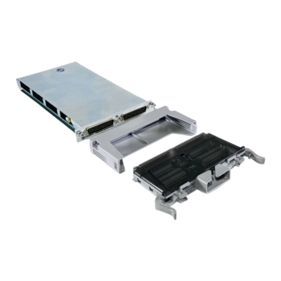
Agilent 34937T
32 Ch GP Switch Terminal Block
A l l t r a d e m a r k s , b r a n d n a m e s , a n d b r a n d s a p p e a r i n g h e r e i n a r e t h e p r o p e r t y o f t h e i r r e s p e c t i v e o w n e r s .
• C r i t i c a l a n d e x p e d i t e d s e r v i c e s
• I n s t o c k / R e a d y - t o - s h i p
Artisan Scientific Corporation dba Artisan Technology Group is not an affiliate, representative, or authorized distributor for any manufacturer listed herein.
In Stock
Used and in Excellent Condition
Buy Today!
https://www.artisantg.com/63083-10
• We b u y y o u r e x c e s s , u n d e r u t i l i z e d , a n d i d l e e q u i p me n t
• F u l l - s e r v i c e , i n d e p e n d e n t r e p a i r c e n t e r
Advertisement

Related Manuals for Keysight Technologies 34937T


Summary of Contents for Keysight Technologies 34937T
- Page 1 Agilent 34937T 32 Ch GP Switch Terminal Block In Stock Used and in Excellent Condition Buy Today! https://www.artisantg.com/63083-10 A l l t r a d e m a r k s , b r a n d n a m e s , a n d b r a n d s a p p e a r i n g h e r e i n a r e t h e p r o p e r t y o f t h e i r r e s p e c t i v e o w n e r s .
- Page 2 Keysight 34937A-34939A General Purpose Switch Modules User’s Guide...
- Page 3 EXPRESS OR IMPLIED, WITH REGARD agreement and written consent from customarily provided to the public. TO THIS MANUAL AND ANY Keysight Technologies as governed by Accordingly, Keysight provides the INFORMATION CONTAINED HEREIN, United States and international Software to U.S. government INCLUDING BUT NOT LIMITED TO THE copyright laws.
- Page 4 Safety Symbols The following symbols on the instrument and in the documentation indicate precautions which must be taken to maintain safe operation of the instrument. Alternating current (AC) Frame or chassis (ground) terminal Standby supply. Unit is not completely disconnected from ac mains when Caution, risk of electric shock switch is off Caution, risk of danger (refer to this...
- Page 5 Additional Safety Notices The following general safety precautions must be observed during all phases of operation of this instrument. Failure to comply with these precautions or with specific warnings or instructions elsewhere in this manual violates safety standards of design, manufacture, and intended use of the instrument. Keysight Technologies assumes no liability of the customer’s failure to comply with the requirements.
- Page 6 Do Not Remove the Instrument Cover Only qualified, service-trained personal who are aware of the hazards involved should remove instrument covers. Always disconnect the power cable and any external circuits before removing the instrument cover. Do Not Modify the Instrument Do not install substitute parts or perform any unauthorized modification to the product.
- Page 7 Waste Electrical and Electronic Equipment (WEEE) Directive 2002/96/EC This instrument complies with the WEEE Directive (2002/96/EC) marking requirement. This affixed product label indicates that you must not discard this electrical or electronic product in domestic household waste. Product category: With reference to the equipment types in the WEEE directive Annex 1, this instrument is classified as a “Monitoring and Control Instrument”...
- Page 8 ....... .16 34937T Terminal Block ........17 34938A 20-Channel High-Current GP Switch Module .
- Page 9 34939A 64-Channel High-Density Form-A GP Switch Module ..23 34939A Simplified Schematic ......23 34939A D-Sub Connectors .
- Page 10 General Purpose Switch Modules This User’s Guide covers the following two plug-in modules for the Keysight 34980A Multifunction Switch/Measure Unit: 34937A 28-channel Form C and 4-channel Form A 34938A 28-channel 5-amp Form A 34939A 64-Channel High-Density Form A – The 34937A provides independent control of 32 relays, including: –...
- Page 11 Reactive loads (those that include significant inductance or capacitance) can cause voltage spikes or current spikes during switching operations. The general purpose modules are designed for switching reactive loads. The optional 34937T and 34938T terminal blocks have solder pads for adding snubber circuits for the 5 A relays to reduce the reactive transients.
- Page 12 Hardware Power-Fail Jumper A hardware jumper on the 34937A and 34938A modules allows you to define the power-failure states for the modules’ 5 A latching relays. Depending on the position of the jumper, the 5 A relays will either open or maintain state when system power failure occurs.
- Page 13 After a five- to ten-second delay, remove the sheet metal cover from the module and move the position of the jumper mounted on the module. See the figure below for the jumper’s location on the module. Keysight 34937A-34939A User’s Guide...
- Page 14 34937A, 34938A and 34939A SCPI Programming Examples The programming examples below provide you with SCPI command examples to use for actions specific to the general purpose switch modules. The slot and channel addressing scheme used in these examples follow the form sccc where s is the mainframe slot number (1 through 8) and ccc is the channel number.
- Page 15 SYSTem:MODule:PFAil:JUMPer:AMP5? 4 Example: Querying the system for module identify (all modules) following command returns the identify of the module installed in slot 7. SYSTem:CTYPe? 7 Reading Cycle Count and Resetting Modules to Power-On State Example: Reading the cycle count for a relay (all switch modules) following command returns the relay cycle count on channel 7 and channel 16 for a module in slot 1.
- Page 16 34937A 32-Channel GP Switch Module The 34937A general-purpose switch module provides independent control of: – Twenty-eight Form C (SPDT) latching relays rated at 1 A – Four Form A (SPST) latching relays rated at 5 A. You can set the power-failure state for these 5 A relays (see “Hardware Power-Fail Jumper”...
- Page 17 34937A D-Sub Connectors Bank 1 Bank 1 Bank 1 Bank 2 Bank 2 For orientation, the D-sub connector end of the module is facing you. 12NO 8NO 4NO 1NO 13NO 9NO 5NO 29NO 29C 7NO 2NO 14NO 10NO 30NO 30C Reserved 11C 9NC 5NC 2NC 14NC 10NC 6NC 6NO GND 11NO 11NC 7NC...
- Page 18 20 NO 23 NO 26 NO 34937T Terminal Block This terminal block with screw-type connections is labeled with the model number and the abbreviated module name. In addition, space is available on the label for you to write the slot number.
- Page 19 34938A 20-Channel High-Current GP Switch Module The 34938A high-current GP switch module provides twenty 5 A Form A (SPST) relays for general purpose switching needs. You can set the power-failure state for these 5 A relays (see “Hardware Power-Fail Jumper” on page 11).
- Page 20 34938A D-Sub Connectors Bank 1 Bank 1 Bank 2 For orientation, the D-sub connector end of the module is facing you. 50-Pin D-Sub Male Connector Reserved 1NO GND 6NO 4C 10NO 10C 10NO 10C Channel Channel Channel Channel Pins Channel Pins 1Common 3Common...
- Page 21 Bank 2 16NO 16C 11NO 11C 17NO 17C 12NO 12C 13NO 13C 19NO 19C 14NO 14C 15NO 15C 50-Pin D-Sub Male Connector Reserved 11NO 11C 17NO 17C 12NO 13NO 13C 19NO 19C 14NO 14C 15NO 15C GND GND 16NO 16C 17NO 17C 18NO 18C 18NO 18C 19NO 19C 14NO 14C 20NO 20C 20NO 20C Channel...
- Page 22 Pads for user-supplied snubber circuity to alleviate reactive transients. The circuits may consist of resistors, capacitors, varistors, or other elements as needed to reduce the switching voltage and current transients inherent in reactive circuits. Keysight 34937A-34939A User’s Guide...
- Page 23 34939A 64-Channel High-Density Form-A GP Switch Module The 34939A high-density GP switch module provides sixty-four 1 A Form A (SPST) relays for general purpose switching needs. You can set the power-failure state for these relays (see “Hardware Power-Fail Jumper” on page 11). A temperature sensor on these modules triggers system interrupts when NOTE high-carry current-induced heat on the modules reaches a threshold of 70 °C.
- Page 24 34939A D-Sub Connectors Bank 1 Bank 1 Bank 2 For orientation, the D-sub connector end of the module is facing you. 4NO 7C 7NO 10C 10NO 13C 13NO 16NO 18C 18NO 21C 21NO 24C 24NO 27NO 30NO 3NO 6C 6NO 9C 12C 12NO 15NO 19C 19NO 22C 22NO 25C 25NO 28NO NC...
- Page 25 Channel Channel Channel Channel Channel Channel 7 NO 14 NO 21 NO 28 NO No Connect 65 7 Common 14 Common 47 21 Common 13 28 Common 37 No Connect 66 Bank 2 Bank 1 Bank 2 For orientation, the D-sub connector end of the module is facing you.
- Page 26 Channel Channel Channel Channel Channel Channel 38 NO 45 NO 52 NO 59 NO No Connect 59 38 Common 75 45 Common 29 52 Common 5 59 Common 41 No Connect 60 39 NO 46 NO 53 NO 60 NO No Connect 65 39 Common 13 46 Common 9...
- Page 27 C NO C NO C NO C NO C NO C NO C NO C NO C NO C NO C NO C NO C NO C NO C NO C NO C NO C NO C NO C NO C NO C NO C NO C NO C NO C NO C NO C NO C NO C NO C NO C NO C NO C NO C NO C NO C NO C NO C NO C NO C NO C NO...
- Page 28 Index Numerics 34929A pinouts pinouts 34937A 34937A 34938A connector pinouts 34939A description power-fail jumper simplified schematic programming examples snubber circuitry terminal block wiring log safety notices 34938A connector pinouts description simplified schematic temperature sensor snubber circuitry terminal block wiring log 34939A connector pinouts description...
- Page 29 THIS PAGE HAS BEEN INTENTIONALLY LEFT BLANK. Keysight 34937A-34939A User’s Guide...
- Page 30 This information is subject to change without notice. Always refer to the Keysight website for the latest revision. © Keysight Technologies 2016-2019 Edition 3, July 2019 Printed in Malaysia *34980-90037* 34980-90037 www.keysight.com...
Need help?
Do you have a question about the 34937T and is the answer not in the manual?
Questions and answers