Keysight Technologies 34937A User Manual
General purpose switch modules
Hide thumbs
Also See for 34937A:
- User manual (19 pages) ,
- User manual (49 pages) ,
- User manual (31 pages)
Table of Contents
Advertisement
Advertisement
Table of Contents

Related Manuals for Keysight Technologies 34937A


Summary of Contents for Keysight Technologies 34937A
- Page 1 Keysight 34937A-34939A General Purpose Switch Modules User’s Guide...
- Page 2 EXPRESS OR IMPLIED, WITH REGARD agreement and written consent from customarily provided to the public. TO THIS MANUAL AND ANY Keysight Technologies as governed by Accordingly, Keysight provides the INFORMATION CONTAINED HEREIN, United States and international Software to U.S. government INCLUDING BUT NOT LIMITED TO THE copyright laws.
-
Page 3: Safety Symbols
Frame or chassis (ground) terminal Standby supply. Unit is not completely disconnected from ac mains when Caution, risk of electric shock switch is off Caution, risk of danger (refer to this manual for specific Warning or Caution information) Keysight 34937A-34939A User’s Guide... -
Page 4: Additional Safety Notices
(grounding) conductor or disconnection of the protective earth terminal will cause a potential shock hazard that could result in personal injury. Do Not Operate in an Explosive Atmosphere Do not operate the instrument in the presence of flammable gases or fumes. Keysight 34937A-34939A User’s Guide... -
Page 5: Do Not Remove The Instrument Cover
In Case of Damage Instruments that appear damaged or defective should be made inoperative and secured against unintended operation until they can be repaired by qualified service personnel. Keysight 34937A-34939A User’s Guide... -
Page 6: Waste Electrical And Electronic Equipment (Weee) Directive 2002/96/Ec
To contact Keysight for sales and technical support, refer to the support links on the following Keysight websites: – www.keysight.com/find/xxxxx (product-specific information and support, software and documentation updates) – www.keysight.com/find/assist (worldwide contact information for repair and service) Keysight 34937A-34939A User’s Guide... -
Page 7: Table Of Contents
......11 34937A, 34938A and 34939A SCPI Programming Examples ..13 Opening and Closing Channels . - Page 8 ........26 Keysight 34937A-34939A User’s Guide...
-
Page 9: General Purpose Switch Modules
34939A 64-Channel High-Density Form A – The 34937A provides independent control of 32 relays, including: – Twenty-eight Form C relays, each rated for 1 A at 60 W per channel – Four Form A (SPST) relays, each rated for 5 A at 150 W per channel. -
Page 10: Operating Considerations
Operating Considerations. Do not connect either the 34937A, 34938A or 34939A module directly to a WARNING mains power outlet. If it is necessary to switch a mains voltage or any circuit where a large inductive load may be switched, you must add signal conditioning elements to reduce the potential transients before they reach the module or the Analog Buses. -
Page 11: Hardware Power-Fail Jumper
Hardware Power-Fail Jumper A hardware jumper on the 34937A and 34938A modules allows you to define the power-failure states for the modules’ 5 A latching relays. Depending on the position of the jumper, the 5 A relays will either open or maintain state when system power failure occurs. - Page 12 After a five- to ten-second delay, remove the sheet metal cover from the module and move the position of the jumper mounted on the module. See the figure below for the jumper’s location on the module. Keysight 34937A-34939A User’s Guide...
-
Page 13: 34937A, 34938A And 34939A Scpi Programming Examples
4. If this command is sent to a module other than the 34937A or 34938A, “NONE” is returned (no error is generated). In particular, the position of the power-fail jumper on the 34939A module cannot be queried using this commmand. -
Page 14: Reading Cycle Count And Resetting Modules To Power-On State
7 and 16 for a module in slot 1. DIAGnostic:RELay:CYCLes:CLEar (@1007,1016) Example: Resetting Module(s) to power-on state (all modules) following command resets a module in slot 4 to its power-on state. SYSTem:CPON 4 Keysight 34937A-34939A User’s Guide... -
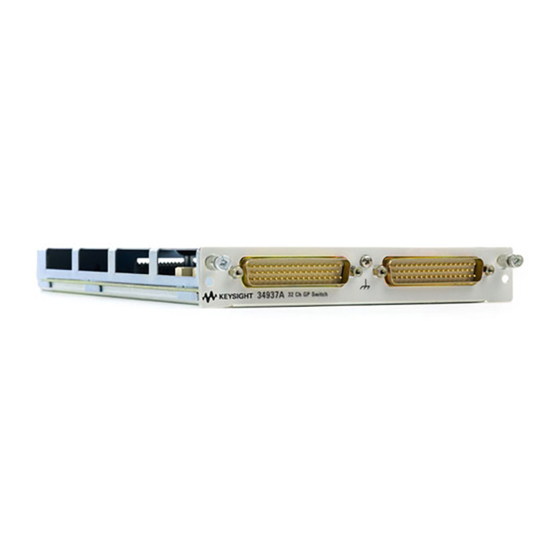
Page 15: 34937A 32-Channel Gp Switch Module
34937A 32-Channel GP Switch Module The 34937A general-purpose switch module provides independent control of: – Twenty-eight Form C (SPDT) latching relays rated at 1 A – Four Form A (SPST) latching relays rated at 5 A. You can set the power-failure state for these 5 A relays (see “Hardware Power-Fail Jumper”... -
Page 16: 34937A D-Sub Connectors
11 NO 14 NO No Connect 17 3 NC 6 NC 9 NC 12 NC 29 NO 3 Common 6 Common 9 Common 12 Common 22 29 Common 2 3 NO 6 NO 9 NO 12 NO Keysight 34937A-34939A User’s Guide... -
Page 17: 34937T Terminal Block
26 NO 34937T Terminal Block This terminal block with screw-type connections is labeled with the model number and the abbreviated module name. In addition, space is available on the label for you to write the slot number. Keysight 34937A-34939A User’s Guide... -
Page 18: 34938A 20-Channel High-Current Gp Switch Module
A temperature sensor on these modules triggers system interrupts when NOTE high-carry current-induced heat on the modules reaches a threshold of 70 °C. See description of the “HOT” annunciator on page 34938A Simplified Schematic Channel 001 (5A Form A) Channel 020 (5A Form A) Keysight 34937A-34939A User’s Guide... -
Page 19: 34938A D-Sub Connectors
4C 10NO 10C 10NO 10C Channel Channel Channel Channel Pins Channel Pins 1Common 3Common 5Common 7Common 9Common 10NO 1Common 4Common 6Common 8Common 10Common 10NO 2Common 4Common 6Common 8Common 10Common Reserved 2Common 4Common 7Common 9Common 3Common 5Common 7Common 9Common No Connect Keysight 34937A-34939A User’s Guide... -
Page 20: 34938T Terminal Block
No Connect 34938T Terminal Block This terminal block with screw-type connections is labeled with the model number and the abbreviated module name. In addition, space is available on the label for you to write the slot number. Keysight 34937A-34939A User’s Guide... - Page 21 Pads for user-supplied snubber circuity to alleviate reactive transients. The circuits may consist of resistors, capacitors, varistors, or other elements as needed to reduce the switching voltage and current transients inherent in reactive circuits. Keysight 34937A-34939A User’s Guide...
-
Page 22: 34939A 64-Channel High-Density Form-A Gp Switch Module
A temperature sensor on these modules triggers system interrupts when NOTE high-carry current-induced heat on the modules reaches a threshold of 70 °C. See description of the “HOT” annunciator on page 34939A Simplified Schematic Channel 001 (1A Form A) Channel 064 (1A Form A) Keysight 34937A-34939A User’s Guide... -
Page 23: 34939A D-Sub Connectors
12 Common 27 19 Common 31 26 Common 55 No Connect 40 6 NO 13 NO 20 NO 27 NO No Connect 59 6 Common 13 Common 7 20 Common 51 27 Common 17 No Connect 60 Keysight 34937A-34939A User’s Guide... - Page 24 50 Common 51 57 Common 21 64 Common 63 Reserved 37 NO 44 NO 51 NO 58 NO No Connect 39 37 Common 77 44 Common 55 51 Common 25 58 Common 1 No Connect 40 Keysight 34937A-34939A User’s Guide...
-
Page 25: 34939T Terminal Block
No Connect 66 34939T Terminal Block This terminal block with screw-type connections is labeled with the model number and the abbreviated module name. In addition, space is available on the label for you to write the slot number. Keysight 34937A-34939A User’s Guide... - Page 26 C NO C NO C NO C NO C NO C NO C NO C NO C NO C NO C NO C NO C NO C NO C NO C NO C NO C NO C NO C NO C NO C NO Keysight 34937A-34939A User’s Guide...
- Page 27 34938A connector pinouts description simplified schematic temperature sensor snubber circuitry terminal block wiring log 34939A connector pinouts description simplified schematic terminal block wiring log connector pinouts 34937A 34938A 34939A D-sub pinouts 34937A 34938A 34939A jumper Keysight 34937A-34939A User’s Guide...
- Page 28 THIS PAGE HAS BEEN INTENTIONALLY LEFT BLANK. Keysight 34937A-34939A User’s Guide...
- Page 29 This information is subject to change without notice. Always refer to the Keysight website for the latest revision. © Keysight Technologies 2016-2019 Edition 3, July 2019 Printed in Malaysia *34980-90037* 34980-90037 www.keysight.com...
Need help?
Do you have a question about the 34937A and is the answer not in the manual?
Questions and answers