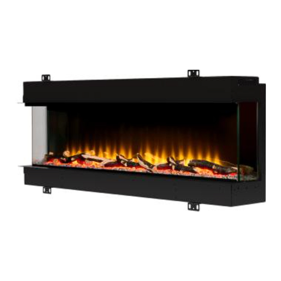
bemodern 1000-3SL Instructions For Installation & Operation
3 sided electric fire
Hide thumbs
Also See for 1000-3SL:
- Manual (50 pages) ,
- Instructions for installation manual (17 pages) ,
- Instructions for installation manual (9 pages)
Table of Contents
Advertisement
Quick Links
Advertisement
Table of Contents

Related Manuals for bemodern 1000-3SL


Summary of Contents for bemodern 1000-3SL
- Page 1 3 Sided Electric Fire 1000 - 3SL (3083) – 1250-3SL (4165) Prior to installing this product locate the data label and note the model and serial number. Model:____________________ Serial Number:___________________________ Instructions For Installation & Operation 200826_1 R1- May 2022...
-
Page 2: Table Of Contents
Contents Page Technical Specification Manual Handling Contents of the Box(es) Unpacking the Fire 6 - 7 Preparing the Fire 8 - 9 Installation – Stud wall 10 - 11 Installing the Fire Fuel Bed Layout Log Positioning Replacing the Glass Troubleshooting 200826_1... -
Page 3: Technical Specification
Technical Specification Detailed: 3 Sided Fire Set Up Dimensions (mm) Fire Logs 5 SML + 2 1000-3SL (3083) 1016 1054 10 SML + 2 1250-3SL (4165) 1266 1304 Tolerance +/- 2mm Boxed Visible Glass Area (mm) Weight Fire D 2/3 Sided... -
Page 4: Manual Handling
Manual Handling BEFORE STARTING THE INSTALLATION OF THIS FIRE, PLEASE READ THE FOLLOWING: CAUTION: This appliance is heavy. Always seek assistance whilst unpacking and / or during installation. The installation should be carried out by two adults to avoid injury or damage. If for any reason it is considered too heavy, please obtain assistance. -
Page 5: Contents Of The Box(Es)
(For 1, 2 & 3 Sided Installation, boxed separately at the rear of the fire). Please ensure all fixings are present before commencing installation. If anything is missing please call Customer Services on 01914300901 or email us at customerservices@bemodern.co.uk 200826_1... -
Page 6: Unpacking The Fire
There is 1 X Screw and 1 X Bracket either side of the fire. See Diagram 3. PACKAGING Diagram 3 Please ensure all fixings are present before commencing installation. If anything is missing please call Customer Services on 01914300901 or email us at customerservices@bemodern.co.uk 200826_1... - Page 7 Unpacking The Fire Continued….. Once the screws are removed - the Glass can be angled forward from the top of the fire and lifted out of the channel at the base of the glass. Note: Place the Glass, 2 x Glass Brackets and 2 x Screws in a safe place- these will be required later.
-
Page 8: Preparing The Fire
Preparing the Fire 1 Sided (Fully Recessed) Installation The fire comes out the box, set up for a 3 sided installation. See Diagram 11 For a 1 Sided Installation. Remove the 6 x Screws and 2 x Small Side Brackets and 1 x Large Side Bracket from either side of the fire. - Page 9 Preparing The Fire Continued….. Next locate and fit the 2 x Fixing Brackets to the top of the fire. Remove the 4 x Screws in the top of the fire and fit the brackets in the required positions. Note: Leave the brackets folded down and the screws backed off slightly until the fire is lifted into the stud wall.
-
Page 10: Installation- Stud Wall
Installation- Stud wall Once the fire has been prepared, use the following opening dimensions to construct the stud wall which the fire will be housed in. It is essential to include a header at the required height to ensure the appliance does not support the weight of the finished wall- See Diagrams 12, 13 and 14. - Page 11 Installation- Stud wall continued….. 2 Sided Installation (Righthand Shown) REQUIRED OPENING DIMENSIONS (mm) FIRE 1000 3SL 1025** 235* 1250 3SL 1275** 235* * + TT- Timber Thickness Note: ** Where possible we recommend the stud wall is built around the fire to allow for any manufacturing tolerances.
-
Page 12: Installing The Fire
Installing The Fire Note: The fire is a two adult person lift Lift the fire into the stud wall opening- leaving approx. 50mm of the fire protruding to the front. Unfolded the fixing brackets at the top and bottom of the fire. -
Page 13: Fuel Bed Layout
Fuel Bed Layout & Log Positioning Tip: Before dressing the fuel bed. Position the foam strip (supplied) in the channel in the base of the fire, this will help to stop the smaller fuel bed material falling into the channel during installation. See Diagram 21. -
Page 14: Replacing The Glass
Replacing the Glass Finally the Glass and 2 x Glass Brackets can be refitted, using the previously removed 2 x Screws. Note: Before proceeding further remove the foam strip and check the channel in the base of the fire is free of any fuel bed material. -
Page 15: Troubleshooting
Switch power to the fire off for 30 minutes to allow safety cut- out to reset. Power up the fire and monitor for overheating, if problem persists contact customer services. Should you be experiencing any problems with your fire please call Customer Services on 01914300901 or email us at customerservices@bemodern.co.uk 200826_1...
Need help?
Do you have a question about the 1000-3SL and is the answer not in the manual?
Questions and answers