Advertisement
Table of Contents
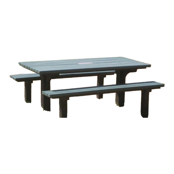
PREMIER
SLIMLINE SETTING
1.8m
In Ground
1.
Place Table & Bench tops face down on a flat surface.
2.
Place supports inside metal frame.
3.
Using a 3.5mm drill bit, drill into the support through the pilot hole in the metal frame.
4.
Using the 40mm Hex screws supplied , screw support onto frame.
Installation
Once the setting has been is assembled, drill or dig holes as per installation diagram.
Place the supports of the assembled setting into the holes. Position the setting and ensure that it is well
braced to prevent movement and sagging. At this stage it is important to use a spirit level to check that the
top is horizontal and the supports are vertical.
Once satisfied that the setting is positioned correctly, fill the holes with concrete, making sure it is packed
firmly around the supports.
Once the concrete has set, remove the bracing.
TABLE:
1 X Table Top ‐ pre‐assembled
2 X Table Supports
16 X 12g x 40mm Hex Screws
ASSEMBLY INSTRUCTIONS
IMPORTANT: Please read carefully before assembling.
COMPONENTS LIST
If you require further installation
assistance, please contact your supplier.
BENCHES:
2 X Bench Tops ‐ pre‐assembled
4 X Bench Supports
24 X 12g x 40mm Hex Screws
Advertisement
Table of Contents

Related Manuals for Replas Premier Slimline PRSS-1800IG


Summary of Contents for Replas Premier Slimline PRSS-1800IG
- Page 1 ASSEMBLY INSTRUCTIONS IMPORTANT: Please read carefully before assembling. PREMIER SLIMLINE SETTING 1.8m In Ground 1. Place Table & Bench tops face down on a flat surface. 2. Place supports inside metal frame. 3. Using a 3.5mm drill bit, drill into the support through the pilot hole in the metal frame. 4. Using the 40mm Hex screws supplied , screw support onto frame. Installation Once the setting has been is assembled, drill or dig holes as per installation diagram. Place the supports of the assembled setting into the holes. Position the setting and ensure that it is well braced to prevent movement and sagging. At this stage it is important to use a spirit level to check that the top is horizontal and the supports are vertical. Once satisfied that the setting is positioned correctly, fill the holes with concrete, making sure it is packed firmly around the supports. Once the concrete has set, remove the bracing. COMPONENTS LIST BENCHES: TABLE: 2 X Bench Tops ‐ pre‐assembled 1 X Table Top ‐ pre‐assembled 4 X Bench Supports 2 X Table Supports 24 X 12g x 40mm Hex Screws 16 X 12g x 40mm Hex Screws If you require further installation assistance, please contact your supplier. ...
- Page 2 SIDE VIEW 1800 mm 25 x 40 x 3mm Frame Ground L evel 1320 mm 755 mm END VIEW WITH BENCHES 280mm 640 mm 640 mm Ground L evel PRSS-1800IG PREMIER SLIMLINE I N GROUND SETTING...
Need help?
Do you have a question about the Premier Slimline PRSS-1800IG and is the answer not in the manual?
Questions and answers