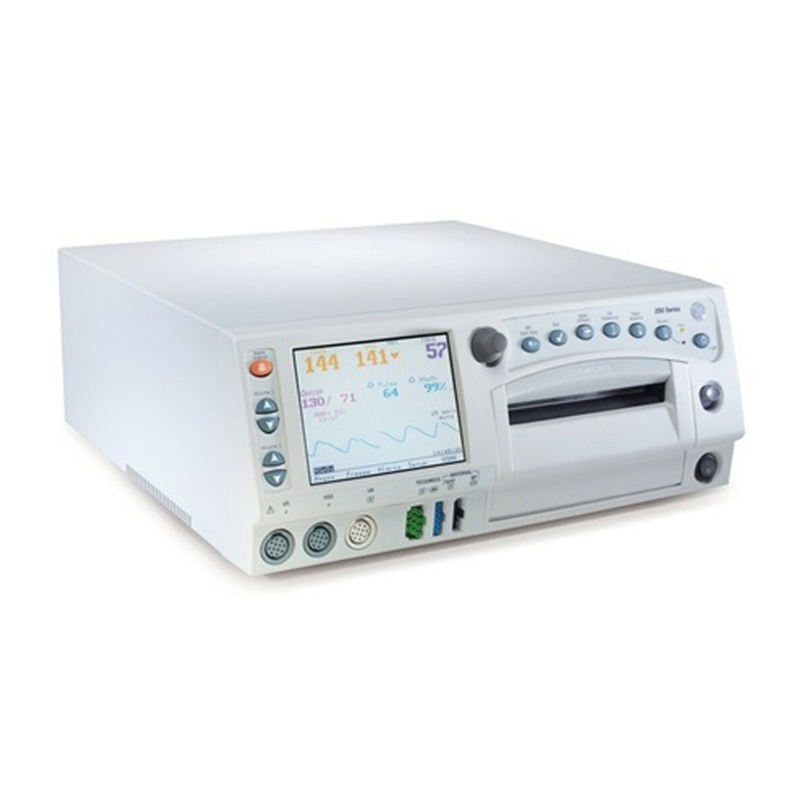
GE Corometrics 250cx Series Operator's Manual
Hide thumbs
Also See for Corometrics 250cx Series:
- Service manual (202 pages) ,
- Service manual (252 pages)


Need help?
Do you have a question about the Corometrics 250cx Series and is the answer not in the manual?
Questions and answers