
Related Manuals for GE CARESCAPE V100


Summary of Contents for GE CARESCAPE V100
- Page 1 GE Healthcare CARESCAPE V100 Vital Signs Monitor ™ Service Manual CARESCAPE V100 Vital Signs Monitor English 2037106-001 B (paper) © 2007, 2008 General Electric Company. All Rights Reserved.
- Page 3 GE Healthcare CARESCAPE V100 Vital Signs Monitor ™ Service Manual CARESCAPE V100 Vital Signs Monitor English 2037106-001 B (paper) © 2007, 2008 General Electric Company. All Rights Reserved.
- Page 4 NOTE: The information in this manual also applies to CARESCAPE V100 Vital Signs Monitor software version RAA. There are no user-apparent differences among these software versions. Due to continuing product innovation, specifications in this manual are subject to change without notice.
-
Page 5: Table Of Contents
Monitor ............1-13 2037106-001B CARESCAPE V100 Vital Signs Monitor... - Page 6 Reference Used to Determine NIBP Accuracy ..... . 2-13 CARESCAPE V100 Monitors With Intra-Arterial Reference (DINAMAP SuperSTAT and Classic Technology) ....2-14 CARESCAPE V100 Monitors With Auscultatory Reference (DINAMAP Auscultatory Reference Technology) .
- Page 7 Replacing the Battery ......... .4-8 2037106-001B CARESCAPE V100 Vital Signs Monitor...
- Page 8 Ordering Parts ........... 6-3 CARESCAPE V100 Vital Signs Monitor...
- Page 9 Temperature ........... . . A-13 2037106-001B CARESCAPE V100 Vital Signs Monitor...
- Page 10 (EMC) ......C-1 Electromagnetic Compatibility (EMC): CARESCAPE V100 Monitor ..C-3 Guidance and Manufacturer’s Declaration –...
-
Page 11: Introduction
Introduction... - Page 12 For your notes CARESCAPE V100 Vital Signs Monitor 2037106-001 B...
-
Page 13: Revision History
Ordering Manuals A paper copy of this manual will be provided upon request. Contact your local GE representative and request the part number on the first page of the manual. Safety Information The information presented in this section is important for the safety of both the patient and operator. -
Page 14: Responsibility Of The Manufacturer
Introduction: Safety Information Responsibility of the Manufacturer GE is responsible for the effects on safety, reliability, and performance only if: assembly operations, extensions, readjustments, modifications, or repairs are carried out by persons authorized by GE; the electrical installation of the relevant room complies with the requirements of appropriate regulations;... -
Page 15: Warnings, Cautions, And Notes
Product Specific Hazards WARNINGS Do not use the CARESCAPE V100 Vital Signs Monitor in the presence of magnetic resonance imaging (MRI) devices. There have been reports of sensors causing patient burns when operating in an MRI environment. - Page 16 CAUTIONS Do not use replacement batteries other than the type supplied with the Monitor. Replacement batteries are available from GE Medical Systems - Accessories and Supplies. The V100 Monitor is designed to conform to Electromagnetic...
-
Page 17: Equipment Symbols
+ / - Increase / decrease adjustable settings Menu Inflate/Stop Cycle History Print On/Off External communications port connector Battery Power Charging External DC power input Class II equipment according to IEC 60536 Defibrillator-proof type BF equipment 2037106-001 B CARESCAPE V100 Vital Signs Monitor... - Page 18 Please contact an authorized representative of the manufacturer for information concerning the decommissioning of your equipment. The CARESCAPE V100 Vital Signs Monitor is protected IPX1 against vertically falling drops of water and conforms with the IEC 529 standard at level of IPX1. Vertically falling drops shall have no harmful effects to the Monitor.
-
Page 19: Service Requirements
Any unauthorized attempt to repair equipment under warranty voids that warranty. It is the user’s responsibility to report the need for service to GE Medical Systems Information Technologies or to one of GE’s authorized agents. Failure on the part of the responsible individual, hospital or institution using this equipment to implement a satisfactory maintenance schedule may cause undue equipment failure and possible health hazards. -
Page 20: Intended Use
If you are unable to resolve the problem after checking these items, contact GE Medical Systems Information Technologies. Prior to calling, please be prepared to provide:... -
Page 21: Service
The Customer Support representative will record all necessary information and will provide you with a Return Merchandise Authorization Number (RMA). Prior to returning any product for repair, you must have a RMA number. Contact GE Medical Systems Information Technologies. Packing Instructions Follow these recommended packing instructions. -
Page 22: Service No Charge Rental
All loaners provided to customers must be returned within the specified time stated on the loaner agreement or a rental fee will be incurred. Repair Parts Repair parts can be ordered from GE Medical Systems Information Technologies: Via phone: 1-800-558-7044, or Via FAX: 1-800-421-6841 Exchange replacement assemblies such as Circuit Board Assemblies also are available;... -
Page 23: Patient Applied Parts
At the end of its service life, the product described in this manual, as well as its accessories, must be disposed of in compliance with the guidelines regulating the disposal of such products. If you have questions concerning disposal of the product, please contact GE Medical Systems Information Technologies or its representatives. 2037106-001 B... - Page 24 Introduction: Disposal of Product Waste 1-14 CARESCAPE V100 Vital Signs Monitor 2037106-001 B...
-
Page 25: Equipment Overview
Equipment Overview... - Page 26 For your notes CARESCAPE V100 Vital Signs Monitor 2037106-001 B...
-
Page 27: Equipment Description
Unpack the items carefully, and check them against the checklists enclosed within the accessory boxes. If an accessory is missing or if an item is in a nonworking condition, contact GE Medical Systems Information Technologies Customer Service immediately. -
Page 28: Basic Components
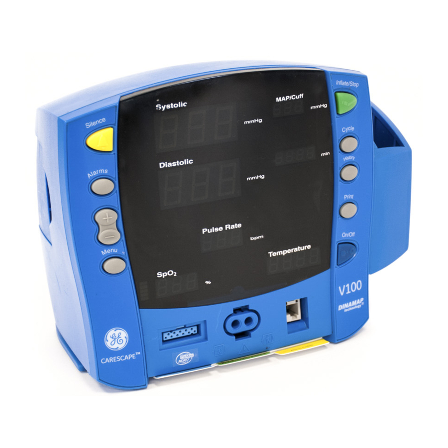
Inflate/Stop button: starts a manual NIBP determination or stop any NIBP determination. Temperature probe holster: stores temperature probe. Cycle button: used to select NIBP mode of manual, auto cycle, or Stat mode. 10. Temperature probe cover storage: stores probe covers. CARESCAPE V100 Vital Signs Monitor 2037106-001 B... -
Page 29: Front Panel
LED bar indicates that pulses are being derived from SpO signals. 23. SpO window: indicates oxygen saturation in %. 24. MAP/Cuff window: indicates measured mean arterial pressure (MAP) in mmHg and shows cuff pressure during NIBP determination. 2037106-001 B CARESCAPE V100 Vital Signs Monitor... - Page 30 (45 min or less when solid; 5 min or less when flashing). 32. CHARGING indicator: lights green to indicate presence of external power source and battery charging. 33. Temperature window: lights 4-digit red LED to indicate measured temperature. CARESCAPE V100 Vital Signs Monitor 2037106-001 B...
-
Page 31: Product Compliance
Equipment Overview: Product Compliance Product Compliance The CARESCAPE V100 Monitor is classified in the following categories for compliance with IEC 60601-1: Internally powered or Class II when powered from external supply Transportable For continuous operation Not suitable for use in the presence of flammable anesthetics... -
Page 32: Theory Of Operation
V100 Monitor. NOTES Prior to each use, inspect the power supply cord to ensure proper connection and condition. Be sure to unplug the Monitor before transport. CARESCAPE V100 Vital Signs Monitor 2037106-001 B... -
Page 33: Spo2
OVERPRESSURE signal is routed to the Pneumatics to release the air pressure. The Main Board also generates an alarm condition with the speaker sounding and error code message on the UI Board. 2037106-001 B CARESCAPE V100 Vital Signs Monitor... -
Page 34: Dinamap Superstat Algorithm
8 mmHg. The parameter then deflates the cuff (to zero detected pressure), analyzes the stored data, and updates the screen. 2-10 CARESCAPE V100 Vital Signs Monitor 2037106-001 B... -
Page 35: Systolic Search
WARNING Arrhythmias will increase the time required by the NIBP parameter to determine a blood pressure. 2037106-001 B CARESCAPE V100 Vital Signs Monitor 2-11... -
Page 36: Dinamap Classic And Auscultatory Reference Algorithm
7 mmHg. The monitor then deflates the cuff (to zero detected pressure), analyzes the stored data, and updates the screen. 2-12 CARESCAPE V100 Vital Signs Monitor 2037106-001 B... -
Page 37: Systolic Search
The reference blood pressures may also be obtained by noninvasive methods like auscultatory method (using cuff and stethoscope). NOTE: For neonatal mode, the reference is always the intra-arterial pressure monitoring method. 2037106-001 B CARESCAPE V100 Vital Signs Monitor 2-13... -
Page 38: Carescape V100 Monitors With Intra-Arterial Reference (Dinamap Superstat And Classic Technology)
Equipment Overview: Functional Description CARESCAPE V100 Monitors With Intra-Arterial Reference (DINAMAP SuperSTAT and Classic Technology) For these monitors, the NIBP is referenced to the invasive blood pressure obtained at the central aortic region. CARESCAPE V100 Monitors With Auscultatory Reference (DINAMAP Auscultatory Reference Technology) In these monitors, the reference blood pressure is the auscultatory method for adult and pediatric populations. -
Page 39: Main Board Pwa
HIGH on the 16 outputs of the 1-of-16 decoder/ demultiplexer one at a time and then reads at the signal on SW_MUX. A LOW on SW_MUX indicates that the switch is asserted. 2037106-001 B CARESCAPE V100 Vital Signs Monitor 2-15... -
Page 40: Spo2 Pwa
Optical Switch The optical switch indicates whether the temperature probe is inserted in the probe holder or not. The Main Board powers the switch. 2-16 CARESCAPE V100 Vital Signs Monitor 2037106-001 B... - Page 41 Equipment Overview: Functional Description 2037106-001 B CARESCAPE V100 Vital Signs Monitor 2-17...
- Page 42 Equipment Overview: Functional Description 2-18 CARESCAPE V100 Vital Signs Monitor 2037106-001 B...
-
Page 43: Installation
Installation... - Page 44 For your notes CARESCAPE V100 Vital Signs Monitor 2037106-001 B...
-
Page 45: Connections
Installation: Connections Connections Right-Side Panel External DC power socket: used with approved GE Medical Systems Information Technologies AC-DC power converter ONLY. Rear Panel Data interface connector: host communications port (15 pin D-type RS-232 serial port) for use only with equipment conforming to IEC 60601-1, configured to comply with IEC 60601-1-1. -
Page 46: Powering The Monitor
To ensure full charge cycles, replace only with a the specified battery. If the monitor is to be stored for some time, first charge the battery and then remove it and store it separately from the monitor. CARESCAPE V100 Vital Signs Monitor 2037106-001 B... -
Page 47: Battery Ok
No error code is displayed. The BATTERY LOW indicator flashes. The monitor alarms for 2.5 minutes then shuts down completely. CAUTION You must plug the monitor into DC power before resuming monitoring. 2037106-001 B CARESCAPE V100 Vital Signs Monitor... -
Page 48: E13 Battery Low
CHARGING will illuminate green on the front of the Monitor indicating that an AC source is available. Prior to usage it is necessary to charge the Monitor for 12 hours. This charge calibrates the battery charging circuitry with the charge status of the battery. CARESCAPE V100 Vital Signs Monitor 2037106-001 B... -
Page 49: Configuring Your V100 Monitor
STAT if the monitor is configured with DINAMAP SuperSTAT Algorithm CLAS if the monitor is configured with DINAMAP Classic Algorithm Display Window Major software revision Systolic Minor software revision Diastolic Type of NIBP technology 2037106-001 B CARESCAPE V100 Vital Signs Monitor... - Page 50 Fast Sat Mode 0=Off, 1=On* (Masimo only) sensitivity 1, 2, 3 1= Low Perfusion-Maximized, 2= Low Perfusion-Default, 3= for (Masimo only) engaging Adaptive Probe Off Technology algorithm* Temperature Temperature blank C or F indicator illuminated CARESCAPE V100 Vital Signs Monitor 2037106-001 B...
- Page 51 On/Off button for 3 seconds. Use the +/- buttons to increment or decrement the inflate pressure default setting. To exit the configuration mode, turn the unit off. To continue with additional configuration settings, press Menu. 2037106-001 B CARESCAPE V100 Vital Signs Monitor...
- Page 52 Press the Menu button until n0d (response mode) appears in the Pulse Rate window. Use the +/- buttons to select the option. Press the Menu button once. SAt (SatSeconds) appears in the Pulse Rate window. Use the +/- buttons to select the option. 3-10 CARESCAPE V100 Vital Signs Monitor 2037106-001 B...
-
Page 53: Advanced Configuration Mode
ACF). You can use the + and - buttons to make changes to settings. After making changes, simply cycle the power to return to normal operation mode. Changes are automatically be retained. 2037106-001 B CARESCAPE V100 Vital Signs Monitor 3-11... -
Page 54: Service Mode
Only transducer calibration pages are available until calibration is valid. Calibration and other service mode setting changes will not be retained unless the “Save Settings” operation is executed (on the final Service Mode options page). 3-12 CARESCAPE V100 Vital Signs Monitor 2037106-001 B... - Page 55 1: Nellcor 2: Masimo 3: Ohmeda (Warning: Incorrect setting will cause fatal 930 alarm during operation.) 5 (in “min” window) Temperature loaded (Displayed in Temperature display window) 0: No Temp 1: Turbo Temp 2037106-001 B CARESCAPE V100 Vital Signs Monitor 3-13...
- Page 56 Warning: The number displayed in the “MAP/Cuff” window will decrease each time the “Save Settings” operation is done. If it reaches zero, a fatal 975 alarm (calibration space exhausted) results and the unit will have to be serviced before operation will be possible again. 3-14 CARESCAPE V100 Vital Signs Monitor 2037106-001 B...
-
Page 57: Host Communications Connector
IEC 60601-1-1 ONLY. Where isolation of data communication is required, GE Medical Systems Information Technologies part number ILC1926 should be used. If external alarm control is required, GE Medical Systems Information Technologies part number 487208CR (Isolated Remote Alarm Cable. - Page 58 Inverted TTL Transmit Data Inverted TTL Receive Data +5 volts No connection No connection Common Remote Alarm No connection No connection RS232 Transmit Data (TxD) No connection RS232 Receive Data (RxD) No connection No connection 3-16 CARESCAPE V100 Vital Signs Monitor 2037106-001 B...
-
Page 59: Maintenance
Maintenance... - Page 60 For your notes CARESCAPE V100 Vital Signs Monitor 2037106-001 B...
-
Page 61: Preventative Maintenance
Physical damage to a flat panel display glass may pose an implosion hazard. Have the flat panel display replaced by qualified service personnel if necessary. Safety labels and inscription on the device are clearly legible. 2037106-001 B CARESCAPE V100 Vital Signs Monitor... -
Page 62: Cleaning
Betadine Alcohol- or petroleum-based cleaning agents Any type of solution that contains ammonium chloride, conductive solutions, wax or wax compounds Sodium salts NOTE: Never autoclave or steam clean the monitor, cuffs, or accessories. CARESCAPE V100 Vital Signs Monitor 2037106-001 B... -
Page 63: Cuffs
Wipe away any excess solution and rinse the cuff again with distilled water. Allow 2 hours for drying. NOTE: The user has the responsibility to validate any deviations from the recommended method of cleaning and disinfection. 2037106-001 B CARESCAPE V100 Vital Signs Monitor... -
Page 64: Temperature Devices
Maintenance: Long-Term Storage For additional information on infection control procedures, contact GE Medical Systems Information Technologies Technical Support. Temperature Devices Do not immerse predictive temperature probes. The probe may be cleaned with a solution of 10% bleach in water. Use a cloth or sponge—just damp, not wet—... -
Page 65: Battery Care
Monitor with the battery in a discharged condition. When the battery will no longer hold a charge, remove and replace it. Failure to replace the battery with the same GE Medical Systems Information Technologies part number may result in shorter battery life. Battery charging will take place as long as the Monitor remains connected to an external DC power source. -
Page 66: Replacing The Battery
Configured settings and time/date will NOT be lost when reset due to pressing and holding the On/Off button regardless of whether the DC charger is attached. Configured settings and time/date will NOT be lost when the battery is CARESCAPE V100 Vital Signs Monitor 2037106-001 B... -
Page 67: Fuses
Do not touch either the pin of the DC input connector or the terminals within the battery compartment and the patient at the same time. Replacement batteries can be obtained from GE Medical Systems Information Technologies. Fuses The monitor contains three fuses. The fuses are mounted within the monitor. The fuses protect the low voltage DC input, the battery, and the remote alarm output. -
Page 68: Ohmeda, Nellcor, And Masimo Spo2 Technologies
Digital manometer (with range to 350 mmHg) Stopwatch/timer (capable of measuring seconds) Adult NIBP cuff, Neonate NIBP cuff, hose, inflation bulb, and associated tubing Calibration kit (p/n 320246, available through GE Medical Systems cable (for appropriate SpO type, if SpO is installed) TE 1811 Temperature Probe Simulator (if TEMP is installed) available from Cardinal Health, Inc. -
Page 69: Parameter Test Procedures
Diastolic Diastolic AUTO CYCLE Alarms Cycle HIGH BP CUFF HISTORY History Pulse Rate Pulse Rate BATTERY INFLATE PRESSURE Print HIGH ALARM VOLUME Menu PULSE VOLUME CHARGING Temperature Temperature On / Off HIGH 2037106-001 B CARESCAPE V100 Vital Signs Monitor 4-11... -
Page 70: Pneumatic Leakage Testing
14. Use the valve on the bulb to reduce pressure to 50 mmHg. 15. Record and verify the pressure reading that appears in the Systolic window. 16. Record and verify the pressure reading that appears in the Diastolic window. 4-12 CARESCAPE V100 Vital Signs Monitor 2037106-001 B... -
Page 71: Pressure Transducer Calibration
Use the inflation bulb to inflate close to 150 mmHg. Slowly inflate (1 to 2 mmHg/sec) until valve opens and pressure is released. Record and verify pressure at which valve opens. Turn unit off. 2037106-001 B CARESCAPE V100 Vital Signs Monitor 4-13... -
Page 72: Button Testing
Wait 1 minute, then press Cycle button until stat is displayed in the min window to initiate a determination in STAT mode. Record Systolic, Diastolic, map and heart rate from the Monitor display. Press Start/Stop button, end STAT mode. 4-14 CARESCAPE V100 Vital Signs Monitor 2037106-001 B... -
Page 73: Nibp Overpressure Verification
Disconnect the temp probe cable from the monitor. Connect Temp simulator; set to 80.2°F. Turn the Monitor on. Put the Monitor into temp monitor mode: partially remove the probe from the well (stop when you hear the Monitor beep). 2037106-001 B CARESCAPE V100 Vital Signs Monitor 4-15... -
Page 74: Spo2 (Perform Only If Equipped With Spo2 Module)
Verify the unit displays a: Pulse Value Saturation value Signal Strength bar Graph Printer Output Test Load Paper into the print mechanism. Press Print button. Verify the printer outputs a record and print quality is good. 4-16 CARESCAPE V100 Vital Signs Monitor 2037106-001 B... -
Page 75: Safety Testing
Setup an IEC 60601-1 approved leakage tester to apply 240 VAC to the isolated temperature circuit. Plug temp probe adapter into the temp jack. Activate the Leakage Tester, verify and record the temp circuit leakage current. 2037106-001 B CARESCAPE V100 Vital Signs Monitor 4-17... -
Page 76: Test Results Form
"Silenced" LEDs flash Overpressure alarm can be cleared Alarm button is functioning DISPLAY All 7-Segment LEDs Light Correct Color All Discrete LEDs Light, Correct Color EXTERNAL DC DETECTION Charging indicator LED illuminated 4-18 CARESCAPE V100 Vital Signs Monitor 2037106-001 B... - Page 77 “---” displayed on SpO display Alarm is silenced, error display remains Pulse Value Saturation Value Displayed Signal Strength Bar PRINTER TEST Printout is generated cleanly Temp Circuit Leakage Current (µA) Circuit Leakage Current (µA) 2037106-001 B CARESCAPE V100 Vital Signs Monitor 4-19...
- Page 78 Maintenance: Test Results Form 4-20 CARESCAPE V100 Vital Signs Monitor 2037106-001 B...
-
Page 79: Troubleshooting
Troubleshooting... - Page 80 For your notes CARESCAPE V100 Vital Signs Monitor 2037106-001 B...
-
Page 81: Alarm Code Interpretation
(oldest appears first). The Systolic window shows the Year the error occurred. The Diastolic window shows the Day the error occurred. The MAP window shows the Month the error occurred. 2037106-001 B CARESCAPE V100 Vital Signs Monitor... - Page 82 Time the error occurred. The Pulse Rate window shows the error code that occurred at the recorded time. 10. To print the error log, press the Print button while viewing the log. CARESCAPE V100 Vital Signs Monitor 2037106-001 B...
-
Page 83: Error Codes
Could not save calibration data Mains PWA issue System Power supply voltage has peaked External power brick issue above 18 Volts (incorrect power supply) System Unknown power processor mode Mains PWA issue received on power-up 2037106-001 B CARESCAPE V100 Vital Signs Monitor... - Page 84 Check for correct probe Temp Temperature probe too hot Replace probe NIBP Overpressure Check for pinched or occluded internal tubing NIBP Excess air in cuff Wrong cuff type Failed valve on pneumatics assembly CARESCAPE V100 Vital Signs Monitor 2037106-001 B...
- Page 85 NIBP level timeout Cuff placement on patient Minor leak in cuff Pneumatic assembly failure NIBP NIBP no determination Cuff placement on patient *Acknowledging an alarm by pressing the Silence button, cancels the alarm. 2037106-001 B CARESCAPE V100 Vital Signs Monitor...
- Page 86 Troubleshooting: Alarm Code Interpretation CARESCAPE V100 Vital Signs Monitor 2037106-001 B...
-
Page 87: Parts List, Drawings, And Replacement
Parts List, Drawings, and Replacement... - Page 88 For your notes CARESCAPE V100 Vital Signs Monitor 2037106-001 B...
-
Page 89: Ordering Parts
This section of the manual provides parts lists for the V100 Monitor. Parts lists should be used in conjunction with the other chapters of this manual. GE makes every effort possible to provide the most up-to-date reference documentation for your equipment. However, in special cases involving field- installed upgrades, the revision level of a diagram or parts list in this manual may not reflect the revision level of your unit’s subassemblies. - Page 90 OXIBAND (OXI-A/N) Adult/Neonate Sensor 414248-002 - Sensor OXIBAND (OXI-A/N) Adult/Neonate Sensor 70124035 (EMEA) - Sensor Nellcor Multisite Sensor D-YS Reusable 70124033 - Sensor Nellcor DuraSensor DS-100A 70124021 - Sensor Nellcor DuraSensor DS-100A 407705-006 (US) CARESCAPE V100 Vital Signs Monitor 2037106-001 B...
- Page 91 Masimo LNOP Reusable Finger Sensor Adult DC-195 2009745-001 - Sensor Masimo LNCS DCI Reusable Adult Sensor 2027258-001 - Sensor Masimo LNCS DCIP Reusable Pediatric Sensor 2027259-001 - Sensor Masimo LNCS TC-I TipClip Reusable Ear Sensor 2027261-001 2037106-001 B CARESCAPE V100 Vital Signs Monitor...
- Page 92 Replacement Paper Printer paper roll - 10/box 089100 Mounting Options Roll Stand Rollstand, CARESCAPE, GCX Version 2033297-001 Pole Mount Pole Mount 2009762-001 Power Supply Mounting Bracket 12W Power supply roll stand bracket 2016929-001 CARESCAPE V100 Vital Signs Monitor 2037106-001 B...
- Page 93 IR adaptor kit with bracket 2026273-002 Remote Alarm Remote Alarm Cable 487208CR Manuals Operation Manual - Paper CARESCAPE V100 Operator’s Manual, Hard Copy 2036991-001 Service Manual - Paper CARESCAPE V100 Service Manual, Hard Copy 2037106-001 Service Manual - CD CARESCAPE V100 Service Manual, CD...
-
Page 94: Field-Replaceable Units (Frus)
FRU CARESCAPE V100 Pneumatic Kit 2037103-016 FRU CARESCAPE V100 BATTERY (X1 BATT) 633178CR BATTERY, LEAD-ACID, 6-VOLT, 3.0 AH 2037103-017 FRU CARESCAPE V100 Speaker 2037103-018 FRU CARESCAPE V100 Cable kit 2037103-019 FRU CARESCAPE V100 Fascia Kit - EN CARESCAPE V100 Vital Signs Monitor 2037106-001 B... - Page 95 FRU CARESCAPE V100 SpO MASIMO 2037103-024 FRU CARESCAPE V100 SpO OHMEDA 2037103-025 FRU CARESCAPE V100 Fascia Kit - GER 2037103-027 FRU CARESCAPE V100 Fascia Kit - CZ 2037103-028 FRU CARESCAPE V100 Fascia Kit - DA 2037103-029 FRU CARESCAPE V100 Fascia Kit - DU...
- Page 96 Parts List, Drawings, and Replacement: Service Parts Bubble Number Part Number Description 2037103-054 FRU CARESCAPE V100 BZL, (BP & SpO & TEMP) 2037103-056 FRU CARESCAPE V100 BATTERY (X5 BATTS) All SpO technology labels included. Select applicable label per monitor configuration.
-
Page 97: Fru Photos
Parts List, Drawings, and Replacement: Service Parts FRU Photos FRU 2037103-002: CARESCAPE Plastic Kit No Printer FRU 2037103-003: CARESCAPE Plastic Kit W/ Printer NOTE: Rear case with printer shown. FRU 2037103-004: CARESCAPE V100 Temperature Kit 2037106-001 B CARESCAPE V100 Vital Signs Monitor 6-11... - Page 98 Parts List, Drawings, and Replacement: Service Parts FRU 2037103-005: CARESCAPE V100 Printer Assembly FRU 2037103-006: CARESCAPE V100 BZL, (BP ONLY) FRU 2037103-052: CARESCAPE V100 BZL, (BP & TEMP) FRU 2037103-053: CARESCAPE V100 BZL, (BP & SpO FRU 2037103-054: CARESCAPE V100 BZL, (BP & SpO &...
- Page 99 Parts List, Drawings, and Replacement: Service Parts FRU 2037103-007: CARESCAPE V100 Inner Chassis Kit NOTE: Kit includes 4 adhesive-backed feet. FRU 2037103-008: CARESCAPE V100 PRTR Door X1/Rollers X5 NOTE: Kit includes 1 printer door with label and 5 printer rollers. 2037106-001 B...
- Page 100 Parts List, Drawings, and Replacement: Service Parts FRU 2037103-010: CARESCAPE V100 Main Board NOTE 1: Each main board comes with all parameters installed. For monitors that do not include specific options (Printer, SpO , Temperature), these options must be turned off while the monitor is in configuration mode.
- Page 101 FRU 2037103-024: CARESCAPE V100 SpO Ohmeda NOTE 1: All 3 SpO boards shown. Kit includes only one. NOTE 2: Nellcor hardware shown. Kit includes matching hardware. FRU 2037103-015: CARESCAPE V100 Pneumatic Kit 2037106-001 B CARESCAPE V100 Vital Signs Monitor 6-15...
- Page 102 Parts List, Drawings, and Replacement: Service Parts FRU 2037103-016: CARESCAPE V100 Battery (X1 BATT) FRU 2037103-056: CARESCAPE V100 Battery (X5 BATTS) FRU 2037103-017: CARESCAPE V100 Speaker 6-16 CARESCAPE V100 Vital Signs Monitor 2037106-001 B...
- Page 103 Parts List, Drawings, and Replacement: Service Parts FRU 2037103-018: CARESCAPE V100 Cable Kit FRU Number Description Language FRU 2037103-019 CARESCAPE V100 Fascia Kit FRU 2037103-025 CARESCAPE V100 Fascia Kit FRU 2037103-026 CARESCAPE V100 Fascia Kit FRU 2037103-027 CARESCAPE V100 Fascia Kit...
- Page 104 FRU 2037103-039 CARESCAPE V100 Fascia Kit POR (CONT.) FRU 2037103-040 CARESCAPE V100 Fascia Kit FRU 2037103-041 CARESCAPE V100 Fascia Kit FRU 2037103-042 CARESCAPE V100 Fascia Kit FRU 2037103-043 CARESCAPE V100 Fascia Kit 6-18 CARESCAPE V100 Vital Signs Monitor 2037106-001 B...
- Page 105 Parts List, Drawings, and Replacement: Service Parts FRU 2037103-022: CARESCAPE V100 All Hardware Kit NOTE: Each Hardware kit includes the following: Description ADHESIVE BACKED CABLE TIE MOUNT,.75X.75 CABLE TIE, LOCKING, NYLON 6.6,3.1"X0.09” CABLE TYE WRAP CONN PLASTIC TEE EXTRUSION GROMMET,HANDLE FILTER 40 MICRON FOOT,RND,12.7 DIA X 3.5H SELF ADHSV...
- Page 106 TUBING SILICONE CLEAR 3/32" ID 7/32" OD 1 foot WSHR,#10 FENDER WASHER 1.00" OD STAINLE FRU 2037103-022: CARESCAPE V100 Keypad Kit NOTE: Printer version shown. For non-printer versions, the print key will need to be trimmed before installation. See FRU installation instructions and parts...
-
Page 107: Fru Main Reference Guide Drawing
Parts List, Drawings, and Replacement: Service Parts FRU Main Reference Guide Drawing For quick reference use the following FRU Main Reference Guide drawing. 2037106-001 B CARESCAPE V100 Vital Signs Monitor 6-21... - Page 108 Parts List, Drawings, and Replacement: Service Parts 6-22 CARESCAPE V100 Vital Signs Monitor 2037106-001 B...
- Page 109 Parts List, Drawings, and Replacement: Service Parts 2037106-001 B CARESCAPE V100 Vital Signs Monitor 6-23...
- Page 110 Parts List, Drawings, and Replacement: 6-24 CARESCAPE V100 Vital Signs Monitor 2037106-001 B...
- Page 111 Parts List, Drawings, and Replacement: 2037106-001 B CARESCAPE V100 Vital Signs Monitor 6-25...
- Page 112 Parts List, Drawings, and Replacement: 6-26 CARESCAPE V100 Vital Signs Monitor 2037106-001 B...
- Page 113 Parts List, Drawings, and Replacement: 2037106-001 B CARESCAPE V100 Vital Signs Monitor 6-27...
- Page 114 Parts List, Drawings, and Replacement: 6-28 CARESCAPE V100 Vital Signs Monitor 2037106-001 B...
-
Page 115: Assembly/Disassembly Of Frus
Battery Remove 4 screws securing the instruction cards. Remove the battery compartment door and adhesive pad. The battery can now be removed. 2037106-001 B CARESCAPE V100 Vital Signs Monitor 6-29... -
Page 116: Rear Case
Remove 2 screws behind black overlay. Set monitor on its face and open the printer door. Carefully remove the rear case. Unplug speaker cable and temperature module cable (if installed) from circuit board. 6-30 CARESCAPE V100 Vital Signs Monitor 2037106-001 B... -
Page 117: Printer
Unplug air hose from valve and filter. Remove remaining 3 cable assemblies. Locate and release retention tab and slide back sub chassis. Remove sub-chassis and set aside. Remove pneumatic assembly from sub-chassis. 2037106-001 B CARESCAPE V100 Vital Signs Monitor 6-31... -
Page 118: Spo2 Board
NOTE: Threaded standoffs have screws on both ends. Remove SpO board. Front Bezel Remove 2 SpO connector screws. Unplug 2 pneumatic hoses from bezel. Remove 4 torx-head screws along the bottom of main board. Lift unit and remove bezel. 6-32 CARESCAPE V100 Vital Signs Monitor 2037106-001 B... -
Page 119: Main Board
Reverse the above sequence to reassemble the monitor. Be careful not to pinch any cables or tubing during reassembly. NOTE: Updated Instructions may be included in your replacement parts kit, always review all material included in your kit. 2037106-001 B CARESCAPE V100 Vital Signs Monitor 6-33... - Page 120 Parts List, Drawings, and Replacement: Assembly/Disassembly of FRUs 6-34 CARESCAPE V100 Vital Signs Monitor 2037106-001 B...
-
Page 121: Technical Specifications And Default
Technical Specifications and Default Settings... - Page 122 For your notes CARESCAPE V100 Vital Signs Monitor 2037106-001 B...
-
Page 123: Specifications
The +5 V output on the host port connector is regulated by internal supply. Battery Refer to “Battery” Section Environmental Operating temperature + 5°C to + 40°C (+ 41°F to + 104°F) Operating atmospheric pressure 700 hPa to 1060 hPa 2037106-001 B CARESCAPE V100 Vital Signs Monitor... -
Page 124: Printer
Thermal dot array Resolution 384 dots/inch horizontal Paper type The paper roll used by the printer must be compatible with GE PN 770137. Languages printed English, German, French, Italian, Spanish, Portuguese (Brazil and Portugal), Hungarian, Polish, Czech, Finnish, Swedish, Danish, Dutch,... -
Page 125: Ohmeda Spo2
± 3.5% or 3 bpm NOTE: All CARESCAPE V100 Monitor regulatory and accuracy studies have been performed using GE CRITIKON BP cuffs Use only GE CRITIKON BP cuffs. The size, shape, and bladder characteristics can affect the performance of the instrument. Inaccurate readings may occur unless GE CRITIKON BP cuffs are used. - Page 126 ±2 digits without motion Sensor light source Wavelength* Infrared: 930 to 950 nm (nominal) Red 650 to 670 nm (nominal) Average power < 1 mW * Information about wavelength range can be especially useful to clinicians. CARESCAPE V100 Vital Signs Monitor 2037106-001 B...
-
Page 127: Nellcor Spo2
70% to 100% MAX-A, MAX-AL ± 2 digits ± 2 digits MAX-N (adult) ± 3 digits MAX-N (neonate) MAX-P ± 2 digits MAX-I ± 2 digits MAX-FAST ± 2 digits SC-A (adult) ± 2 digits 2037106-001 B CARESCAPE V100 Vital Signs Monitor... - Page 128 The MAX-N, D-YS, OXI-A/N, and OxiCliq N were tested on patients >40 kg. The accuracy specification has been determined between saturations of 80%-100%. *** Information about wavelength range can be especially useful to clinicians. CARESCAPE V100 Vital Signs Monitor 2037106-001 B...
-
Page 129: Masimo Spo2
This variation equals plus or minus, one standard deviation. Plus or minus one standard deviation encompasses 68% of the population. Specifications: Masimo sensor accuracy range Sensor model 70% to 100% LNOP LNOP ADT ± 2 digits without motion LNOP NEO ± 3 digits without motion 2037106-001 B CARESCAPE V100 Vital Signs Monitor... - Page 130 ± 3 digits without motion Resolution Saturation (% SpO Pulse rate (bpm) Low perfusion performance 0.02% Pulse amplitude Saturation (% SpO ) ±2 digits and % transmission >5% Pulse rate ±3 digits A-10 CARESCAPE V100 Vital Signs Monitor 2037106-001 B...
-
Page 131: Temperature
Max: 41.1°C; 106.0°F Min: 35.6°C; 96.0°F Monitor mode Max: 41.1°C; 106.0°F Min: 26.7°C; 80.0°F Monitor mode accuracy ±0.1°C ±0.2°F (when tested in a calibrated liquid bath; meets ASTM E1112, Table 1, in range specified) 2037106-001 B CARESCAPE V100 Vital Signs Monitor A-11... -
Page 132: Battery
Approx. 5 hours from full discharge when the monitor is off Approx. 8 hours when the monitor on Default Settings Alarms Alarm volume NIBP Non- Adult/ped Neonate patient specific Systolic (mmHg) HIGH Diastolic (mmHg) HIGH A-12 CARESCAPE V100 Vital Signs Monitor 2037106-001 B... -
Page 133: Ohmeda Spo2
™ SatSeconds Masimo SpO (%) HIGH alarm limit (%) LOW alarm limit Averaging time 12 seconds FastSAT mode 0 (for Off) Sensitivity mode 2 (for Low Perfusion) Temperature Unit of measure °F 2037106-001 B CARESCAPE V100 Vital Signs Monitor A-13... - Page 134 Technical Specifications and Default Settings: Default Settings A-14 CARESCAPE V100 Vital Signs Monitor 2037106-001 B...
-
Page 135: Appropriate Use Of Nibp Simulators
Appropriate Use of NIBP Simulators... - Page 136 For your notes CARESCAPE V100 Vital Signs Monitor 2037106-001 B...
-
Page 137: Appropriate Use Of Nibp Simulators
NIBP monitors be established through clinical testing - the use of NIBP simulators is not acceptable. GE Healthcare has established accuracy using the AAMI SP-10 standard (2) and a similar standard exists in Europe (3). The AAMI standard specifies that the accuracy of NIBP monitors can be determined using either an invasive (intra- arterial) or noninvasive (auscultatory) blood pressure reference. -
Page 138: What Do Simulator Manufacturers Say
"Since the CuffLink produces the same response independent of the inflate/ deflate cycle or the algorithm used by the monitor, we offer the term "Target Value" as an approximation of the patient's actual blood pressure" (5) CARESCAPE V100 Vital Signs Monitor 2037106-001 B... -
Page 139: Why Use Simulators
The accuracy of an NIBP monitor can only be determined by comparison to a clinical blood pressure reference. NIBP simulators are useful for certain types of testing, but should not be used for accuracy testing. Figure 2A: Cuff Oscillation From A Clinical Measurement 2037106-001 B CARESCAPE V100 Vital Signs Monitor... - Page 140 DNI Nevada CuffLink Non-Invasive Blood Pressure Analyzer, Operating and Service Manual; Revision E, 11/97 NIBP Pump 2 Noninvasive Blood Pressure Simulator and Tester, Operations Manual; Revision C, January 2003 Bio-Tek and NIBP Pump 2 are trademarks of Bio-Tek Instruments. CARESCAPE V100 Vital Signs Monitor 2037106-001 B...
-
Page 141: Electromagnetic Compatibility
Electromagnetic Compatibility (EMC) - Page 142 For your notes CARESCAPE V100 Vital Signs Monitor 2037106-001 B...
-
Page 143: Electromagnetic Compatibility (Emc): Carescape V100 Monitor
Electromagnetic Compatibility (EMC): CARESCAPE V100 Monitor Changes or modifications to this system not expressly approved by GE Medical Systems can cause EMC issues with this or other equipment. This system is designed and tested to comply with applicable regulation regarding EMC and must be installed and put into service according to the EMC information stated in this appendix. -
Page 144: Immunity
Electromagnetic Compatibility (EMC): Electromagnetic Compatibility (EMC): CARESCAPE V100 Monitor Guidance and Manufacturer’s Declaration – Electromagnetic Immunity The CARESCAPE V100 Monitor is intended for use in the electromagnetic environment specified below. It is the responsibility of the customer or user to assure that the V100 Monitor is used in such an environment. - Page 145 Electromagnetic Compatibility (EMC): Electromagnetic Compatibility (EMC): CARESCAPE V100 Monitor Guidance and Manufacturer’s Declaration – Electromagnetic Immunity The V100 Monitor is intended for use in the electromagnetic environment specified below. It is the responsibility of the customer or user to assure that the V100 Monitor is used in such an environment.
-
Page 146: Recommended Separation Distances
Electromagnetic Compatibility (EMC): Electromagnetic Compatibility (EMC): CARESCAPE V100 Monitor Recommended Separation Distances The table below provides the recommended separation distances (in meters) between portable and mobile RF communications equipment and the V100 Monitor. The V100 Monitor is intended for use in the electromagnetic environment on which radiated RF disturbances are controlled. -
Page 147: Compliant Cables And Accessories
Electromagnetic Compatibility (EMC): Electromagnetic Compatibility (EMC): CARESCAPE V100 Monitor Compliant Cables and Accessories CAUTION The use of accessories, transducers and cables other than those specified may result in increased emissions or decreased immunity performance of the equipment or system. The table below lists cables, transducers, and other applicable accessories with which GE Medical Systems claims EMC compliance. - Page 148 Electromagnetic Compatibility (EMC): Electromagnetic Compatibility (EMC): CARESCAPE V100 Monitor Maximum Part No Description Lengths 2002800-001 Masimo LNOP Reusable Finger Sensor LNOP/DCI Adult 1.0 m / 3.3 ft 2027263-002 Masimo LNC-10 cable assembly 3.0 m / 10 ft 2002799-001 Masimo LNOP Reusable Finger Sensor LNOP/DCI Pediatric 1.0 m / 3.3 ft...
- Page 149 Electromagnetic Compatibility (EMC): Electromagnetic Compatibility (EMC): CARESCAPE V100 Monitor Maximum Part No Description Lengths OXY-W-UN Wrap Sensor with UN connector 1.0 m / 3.3 ft OXY-E-UN Ear Sensor with UN connector 1.0 m / 3.3 ft OXY-E4-GE Integrated Ear Sensor 4.0 m / 13.1 ft...
- Page 150 Electromagnetic Compatibility (EMC): Electromagnetic Compatibility (EMC): CARESCAPE V100 Monitor For your notes C-10 CARESCAPE V100 Vital Signs Monitor 2037106-001 B...
- Page 152 + 86 21 5257 4650 Fax: + 1 414 355 3790 Fax: + 49 761 45 43 - 233 Fax: + 86 21 5208 2008 GE Medical Systems Information Technologies, a General Electric Company, going to market as GE Healthcare. www.gehealthcare.com 0459...
Need help?
Do you have a question about the CARESCAPE V100 and is the answer not in the manual?
Questions and answers