Table of Contents
Advertisement
Quick Links
Advertisement
Table of Contents

Summary of Contents for VendNet ST 3000
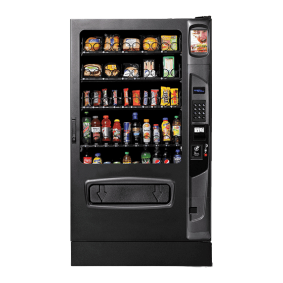
- Page 1 ST/VT SINGLE TEMP/VARIABLE TEMP GLASS FRONT VENDOR MODELS: 3567 / 3567A – ST 3000 (3 WIDE) 3565 / 3565A – ST 5000 (5 WIDE) 3568 / 3568A – VT 3000 (3 WIDE) 3566 / 3566A – VT 5000 (5 WIDE)
- Page 2 S T / V T V E N D O R • 3 5 6 8 3 5 6 7 3 5 6 6 3 5 6 5 • 4 2 2 0 5 5 7 R E V A...
-
Page 3: Table Of Contents
Write them into the spaces below for the vendor, note your machine’s your records. Model and Serial Numbers before contacting: VendNet MODEL NUMBER: _______________ 8040 University Blvd Des Moines, IA 50325 - USA... -
Page 4: Introduction
INTRODUCTION This manual contains instructions, service and installation guidelines for the Single Temp (ST) / Variable Temp (VT) Glass front Vendor. Please read this manual thoroughly and follow the instructions. The initial set-up of a vendor is a very important step of insuring that the equipment operates in a trouble-free manner. -
Page 5: Unpacking
REFRIGERATION MODEL Embraco 1/3 HP TYPE Hermetically Sealed CONTROLS Electronic REFRIGERANT R-134a CHARGE 16 oz COIN CHANGER, BILL VALIDATOR, CARD READER MDB Coin Changer level II or III, Bill Validator Level I, TYPE Card Reader Level I or II VENDOR OPERATION Suitable for indoor use only. - Page 6 REMOVING THE DOOR The vendor will fit through most doorways (34"+) by opening the vendor outer door and carefully walking the vendor door or cabinet thorough first and then moving the remaining portion of the vendor through. The vendor outer door may be temporarily removed to permit easier movement through a narrower door openings or hallways.
- Page 7 POWER CORD INSTALLATION Remove the power cord from inside the vendor. Remove the connection box cover retaining screw and route the cord under the cover. Keep power cord secured on the center back of the cabinet until the vendor is placed into its final location to prevent damage to the cord.
-
Page 8: Loading Products
LOADING PRODUCTS Load products from front to back making sure all items fit freely between the spiral spaces. Do not attempt to force oversize items or packages into the spaces. Do not skip a space. Place the product on the bottom of the compartment on the product spirals with the label facing the front of the vendor for easy identification by the customer. -
Page 9: Tray Adjustments
TRAY ADJUSTMENTS By re-timing the spirals, difficult-to-vend items can be dispensed more dependably. By altering tray spacing, larger items can be vended. By changing the tray configuration, different product mixes can be accommodated VERTICAL SPACING The trays can be adjusted up or down in half-inch increments to provide additional headroom for vending taller products. When increasing the height in one area, the same amount of room will be lost in the tray above or below the one being adjusted. - Page 10 Reverse procedure to re-install tray. Test-vend the tray in its new position to assure that the tray plug is properly seated. 2. Figure 14a. Tray Mounting Nut - Left Front 4. Figure 14b. Tray Mounting Nut - Left Rear Figure 15. Drawer Slide Removal (Left Shown) CANDY, SNACK, AND MEDIUM (3/4) SNACK TRAY ADJUSTMENTS All of the Snack/Candy/Food/Beverage Trays have adjustable divider locations.
-
Page 11: Spiral Adjustement
SPIRAL ADJUSTEMENT The shape, size and thickness of a product affect how well it falls off the tray. Most products can be vended successfully when the spiral end is positioned at 6 o’clock. If vending problems occur with spiral ends at the standard 6 o’clock position, adjust the drop-off either by retiming the spiral or installing a Product Pusher SPIRAL TIMING ADJUST SPIRAL... -
Page 12: Automatic Delivery Lift
Loading Coin Mechanism INSERT COINS THROUGH The Coin Mechanism must be loaded with some level of each coin in FRONT DOOR COIN order for the vendor to operate properly. The coins need to be PRESS SERVICE INSERT TO FILL COIN loaded into the coin mechanism by insertion into the front coin MODE BUTTON TUBES... -
Page 13: Vend Cycle - Ivend® Equipped
portion of the product package blocks the Delivery Lift sensors, indicating that the product has reached the ADA delivery height. The machine display will now show “Please Remove Your Product” and an audible beep will occur every 10 seconds until the product is removed or one minute has elapsed. -
Page 14: Sales Mode
SALES MODE The vendor automatically defaults to Sales Mode after it is turned on. In the Sales Mode, the vendor accepts money deposits, pays out change and dispenses product to the customer. DISPLAY CREDIT - ELECTRONIC PRICING This vendor is equipped with the Electronic Pricing feature. The customer may verify the price by pressing the selection number (i.e. 22) before inserting money. -
Page 15: Service Mode Functions
SERVICE MODE FUNCTIONS TUBE FILL/ DISPENSE COINS TUBE FILL Tube Fill counts coins as STEP DISPLAY they are deposited and Motor Count 60 Press Service Mode Button Shows the dollar amount. At least 15 of each denomination Press and begin depositing coins (Sales Mode) Press 2 times to exit... -
Page 16: Pricing
Auto Lift BUTTON Press to see current auto lift setting. Default is BUTTON * - exit # - save Auto Lift AUTO Press to turn the auto lift AUTO * - exit # - save Auto Lift OFF Press to turn the auto lift OFF * - exit # - save Auto Lift OFF... -
Page 17: Accounting
5.3 ITEM STEP DISPLAY Motors ( - - ) Press Service Mode Button Pricing Press Item Press Item 010 $0.50 Enter Item and price Press to save. The program will automatically go Item 010 $0.50 to the next selection number. (Sales Mode) Press 3 times to exit. -
Page 18: Diagnostics
IMPORTANT: Do not attempt to run the Delivery Lift Test diagnostic if the Delivery Lift Plate may be jammed. Manually correct this issue before running test. Contact Vendnet Service at 1-800-833-4411 for assistance or more information. S T / V T V E N D O R • 3 5 6 8 3 5 6 7 3 5 6 6 3 5 6 5 •... -
Page 19: Temperature Control
0.0.6 LIFT OPTICS ALIGN This indicates if the Delivery Lift Sensors are functioning and aligned so that they can detect when a product is lifted to the correct height. The Green LED on the lift optics board (located behind the iVend Red LED sensor board) will also be illuminated when sensors are aligned. - Page 20 RELAYS The control system controls up to three relays which then control the refrigeration and heating systems: RELAY1— Controls the compressor and the condenser fan (refrigeration system). RELAY2— Controls the evaporator fan (refrigeration system). RELAY3 OPTION— Controls the optional upper zone blower and heater system. DOOR SWITCH The door switch is located in the upper right corner of the vendor door assembly (See Figure 20).
-
Page 21: Health Safety
BOTTOM (COOL) ZONE For a Single Zone vendor, the entire tray compartment is the Bottom (Cool) Zone. For a Dual Zone vendor, the product trays contained below the insulating barrier is the Bottom (Cool) Zone. The evaporator is located between the lowest tray and the compressor. The evaporator fan distributes cold air to products in the bottom zone. -
Page 22: Refrigeration
TO ACTIVATE HEALTH SAFETY TEST MODE STEP DISPLAY Motors ( - - ) Press Service Mode Button Diagnostics Press Password: Press Enter Password (default-2314) HS Test (Current Status) Press *- exit 1- edit HS Test (Choice Flashing) Press to toggle ON/OFF *- exit # - save HS Test (New Status) Press... - Page 23 NOTE The sealed hermetic system should not be worked on outside the Factory Service Center REFRIGERATION TROUBLESHOOTING COMPRESSOR WILL NOT START Problem Possible Causes/Actions Vendor not plugged in. Tripped breaker or blown fuse. Faulty wall outlet Faulty (short or open) power cord. Check power cord with a Multi-Meter.
- Page 24 Faulty temperature sensor or not mounted in the correct position. See Temperature Control section and Factory Default Settings section of this Temperature setting to warm manual. Defective control board UNIT OPERATES LONG OR CONTINUOUSLY Problem Possible Causes/Actions Clogged or blocked in inlet screen, air filter or outlet screen ...
-
Page 25: Preventive Maintenance
TROUBLESHOOTING CIRCUITS WITH MULTI-METER Caution: Power must be disconnected and fan circuit open. To check the power source, use the voltage section of the Multi-Meter. Acceptable range is 103-127VAC for 115V (60Hz), or 195-255VAC 230V (50Hz). Check compressor starting relay. Embraco 1/3 HP –... -
Page 26: Parts Ordering Procedure
If you do not have the right parts manual: contact VendNet™. If you have any questions, check out our Website www.vendnetusa.com or call VendNet. Ask for the Parts Department. We will be happy to assist you. Email: vendnet@vendnetusa.com S T / V T V E N D O R •... -
Page 27: Before Calling For Service
BEFORE CALLING FOR SERVICE Please check the following: Does your vendor have at least 6-inches of clear air space behind it? If the power is turned on at the fuse box, is the vending vendor the only thing that doesn’t work? ... - Page 28 We reserve the right to modify or improve the designs or specifications of such products at any time without notice. VendNet™ 8040 University Blvd...
Need help?
Do you have a question about the ST 3000 and is the answer not in the manual?
Questions and answers