Table of Contents
Advertisement
Quick Links
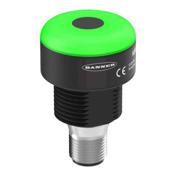
K30 Pro Optical Sensor Instruction Manual
Instruction Manual
30 mm Programmable Multicolor RGB Optical Sensor and Indicator
DO NOT USE THIS DEVICE FOR PERSONNEL PROTECTION
Using this device for personnel protection could result in serious injury or death.
•
This device does not include the self-checking redundant circuitry necessary to allow its use in personnel
safety applications. A device failure or malfunction can cause either an energized (on) or de-energized (off)
output condition.
Models
Family
K30
Overview
The K30 Pro Optical Sensor is an adjustable field optical sensor that can detect a wide variety of materials and objects.
Configure the sensor using software or remote input wires to sense objects up to a specific distance, ignoring objects beyond this distance (background suppression),
or within a windowed range.
Measurement
Reference Point
Model
K30PAF1000
B
E
C
.
ANNER
NGINEERING
ORP
•
Programmable using Banner's Pro Editor software and Pro Converter Cable
•
Up to 7 colors in one device (14 colors using Pro Editor)
•
Devices are completely self-contained—no controller needed
•
Teachable modes with color feedback for ease of use
•
Touchless activation removes the need for physical force to activate
•
Rated IP65
•
10 V DC to 30 V DC operation
•
Resistant to ambient light, EMI, and RFI interference
•
Sensing and indication in one device
!
WARNING
Activation
Style
Method
Output State
P
AF100
A
P = Pro
A = Normally Open
AF100 = 100 mm adjustable field*
AF1000 = 1000 mm adjustable field*
* Detection distance can be adjusted through
teach mode or Pro Editor
Max distance = 1000 mm.
Detection not
possible
D0
D1
D0 (mm)
0
February 7, 2023
Output
Function
Color/Control
Connector
M
GRY3
Q = 5-pin or 8-pin integral
M12 quick disconnect
M = Momentary
depending on model **
GRY3 = Programmable Multicolor
(3 Color, 5-Pin)
GRY4 = Four State, Full Logic Multicolor
(3 Color, 5-Pin)
RGB7 = Programmable Multicolor
(7 Color, 8-Pin)
Detection Area
Reliable detection of a stationary
and moving object
Switch Point D1 (mm)
20
Q
** Models with a quick disconnect
require a mating cordset
D2
Switch Point D2 (mm)
1000
Advertisement
Table of Contents

Related Manuals for Banner K30 Pro


Summary of Contents for Banner K30 Pro
- Page 1 Overview The K30 Pro Optical Sensor is an adjustable field optical sensor that can detect a wide variety of materials and objects. Configure the sensor using software or remote input wires to sense objects up to a specific distance, ignoring objects beyond this distance (background suppression), or within a windowed range.
-
Page 2: Wiring Diagrams
NSTRUCTION ANUAL ANNER NGINEERING Pro Editor Use Banner's Pro Editor software and Pro Converter Cable to create custom configurations by selecting different colors, flash patterns, and animations. For more information visit www.bannerengineering.com/proeditor. Wiring Diagrams Table 1:GRY3 Models Pin 1 = Brown... -
Page 3: Configuring A Sensor
High, pulse the gray or yellow input wire to V+ (10 V DC to 30 V DC). For Active Low, pulse the gray or yellow input wire to ground (0 V DC). The remote input wire is enabled by default. Pulse the remote input wire 7 times or use the Banner Pro Editor software to enable or disable the feature. When the remote input feature is enabled, pulse the remote input according to the diagram and the instructions provided in this manual. - Page 4 Teach Status Color: Blue The K30 Pro Optical Sensor is configured to Object Mode by default. Object Mode sets the total Detection Area from the sensor to the Set Point plus the Offset Value (50 mm default). Use Object Mode to trigger a change in state when an object is present between the sensor minimum (20 mm default) and the taught distance plus the offset.
- Page 5 Reset the sensor to factory default settings using one of two methods. : If a factory reset is performed through the Banner Pro Editor Software, the remote input wire becomes disabled (factory default setting). If the sensor is returned NOTE to factory defaults by using the remote input wire, the input wire remains enabled and the rest of the settings are restored to factory defaults.
-
Page 6: Distance Mode
Pro Converter Cable required to interface between PC and indicator, see warm up accessories Default Indicator Characteristics Color Coordinates Dominant Wavelength (nm)or Color Lumen Output (Typical at 25 Color Temperature (CCT) °C) Green 0.154 0.700 0.689 0.309 Yellow 0.467 0.463 Blue 0.140 0.054 © Banner Engineering Corp. www.bannerengineering.com... - Page 7 Diegem, BELGIUM Essex SS11 8YT, Great Britain Dimensions All measurements are listed in millimeters [inches], unless noted otherwise. Ø 30.0 [1.18] 16.8 [0.66] 18.0 31.8 [0.71] [1.25] 47.8 M22 x 1.5 [1.88] M12 x 1 © Banner Engineering Corp. www.bannerengineering.com...
-
Page 8: Beam Pattern
Mating accessory for cabled and terminal models • 150 mm (6 inch) PVC cable with M12 quick disconnect • Lever wire nuts included (qty 5) • Required to connect cabled models and screw terminal models to Pro Converter Cable, sold separately © Banner Engineering Corp. www.bannerengineering.com... - Page 9 Required to connect 8-pin Pro Series-enabled devices to Pro Converter Cable (MQDC-506-USB), sold separately Cordsets for the K30 Pro Optical Not all models are shown. Please contact Banner for other available lengths and for double-ended cordsets. 5-Pin Threaded M12 Cordsets—Single Ended Model...
- Page 10 Hole center spacing: A = 26.0, A to B = 13.0 Hole size: A = 26.8 x 7.0, B = ø 6.5, C = ø 22.5 LMB22LPC Ø22 • For 28 mm tubular racking • Toolless mount to racking • 22 mm mounting hole Ø27.8 © Banner Engineering Corp. www.bannerengineering.com...
-
Page 11: Banner Engineering Corp Limited Warranty
Banner Engineering Corp Limited Warranty Banner Engineering Corp. warrants its products to be free from defects in material and workmanship for one year following the date of shipment. Banner Engineering Corp. will repair or replace, free of charge, any product of its manufacture which, at the time it is returned to the factory, is found to have been defective during the warranty period.
Need help?
Do you have a question about the K30 Pro and is the answer not in the manual?
Questions and answers