
Related Manuals for HAAS + SOHN HSP 4.0-F2


Summary of Contents for HAAS + SOHN HSP 4.0-F2
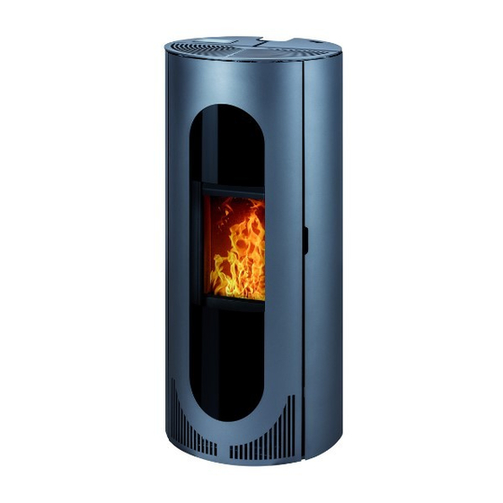
- Page 1 Equipment sheet HSP 4.0–F2 HSP 4.0–F2 Equipment sheet Pellet stove 0545608001403d...
- Page 2 Notes in the text Of utmost importance there are the notes entitled WARNING. The notes entitled WARNING advise you on serious danger of damage to the heating device or of an injury. The note entitled Notice advises you on possible damage to your heating device. The note entitled Important calls your attention to the information important for the operation of your heating device.
-
Page 3: Table Of Contents
Contents 1. Technical data..........................1 2. Dimensions........................... 2 2.1. Flue-pipe conn on the top ......................2 2.2. Flue-pipe conn rear ........................3 2.3. Flue-pipe conn — concentrique....................4 3. Cleaning work ..........................5 3.1. Cleaning the surface ......................... 5 3.2. Cleaning the glass panel ......................5 3.3. -
Page 5: Technical Data
1. Technical data HSP 4.0–F2 456.08 Nominal Partial output Partial output output Heat output range: 8,5 kW 3,7 kW 2,6 kW Nominal heat output: 8,5 kW Test conditions defined by norm: EN 14785 Height: 1206 mm Width: 954 mm Depth: 380 mm Weight: 232 kg... -
Page 6: Dimensions
2. Dimensions 2.1. Flue-pipe conn on the top Pos. 1: for external air input Pos. 2: convection air for 2nd room Pos. 3: flue pipe: inner diameter 80 mm... -
Page 7: Flue-Pipe Conn Rear
2.2. Flue-pipe conn rear Pos. 1: for external air input Pos. 2: convection air for 2nd room Pos. 3: flue pipe: inner diameter 80 mm... -
Page 8: Flue-Pipe Conn - Concentrique
2.3. Flue-pipe conn — concentrique Pos. 1: for external air input Pos. 2: convection air for 2nd room Pos. 3: flue pipe: inner diameter 80 mm... -
Page 9: Cleaning Work
3. Cleaning work WARNING Before starting any cleaning work, the stove must be cool down! Once the cleaning work is completed, the correct operating status of the device must be re- established: Put the combustion pot in correctly, close the combustion chamber door. 3.1. - Page 10 WARNING Cleaning the combustion pot may only be done with a cooled down stove in “OFF” operating mode. Otherwise there is a risk of burns! • Clean the burner with the supplied tool. (By scraping the burner wall, dirt falls down through the cleaning roller into the ash pan.) WARNING Do not dismantle the burner!
- Page 11 Figure 1: Cleaning the combustion pot (using the supplied tool)
-
Page 12: Maintenance Work
4. Maintenance work WARNING Before starting any cleaning work, the stove must be cool down! The mains plug must be pulled out of the power supply socket (always in advance)! The frequency of maintenance in turn depends to a large extent on the pellet quality (ash content). Quality pellets have a low ash content of about 0.2-0.3%. -
Page 13: Cleaning The Flue Gas Passes
4.2. Cleaning the flue gas passes CAUTION Check and clean the flue-gas ways, exhaust (flue-gas) fan and flue-gas ducts at the latest after 1000 kg of pellets have been consumed. Clean with a brush or an ash extractor. CAUTION After completion of the cleaning make sure that when putting back the covers, the seals are seated in the right positions. -
Page 14: Cleaning The Flue Baffle
4.2.1. Cleaning the flue baffle After consuming 1000 kg of pellets or after a year of operation, it is necessary to clean the deflector using the enclosed tool. CAUTION To remove the deflector, you must retract the flame temperature sensor - otherwise the deflector cannot be removed. -
Page 15: Cleaning The Pellet Container - Annual Maintenance
4.3. Cleaning the pellet container - annual maintenance • Heat the pellet stove until the storage tank is completely empty. • Then the protective grille (1) in the pellet tank may be removed. • Then clean the tank and the intake of the screw conveyor housing with a vacuum cleaner. •... -
Page 16: Replacement Parts List
5. Replacement parts list 5.1. Replacement parts list (without trim parts) Description Pos. Piece No. PR Replacement parts list (without trim parts) Complete combustion chamber door/ 1 piece 0545508005300 anthracite Ash-pan door/anthracite 1 piece 0545908005520... - Page 17 Ash pan 1 piece 0545908005604 Protection grate 1 piece 0545508005739 1 piece Burner 0545508005820 Combustion chamber cladding left 1 piece 0545508005212 Combustion chamber cladding back 1 piece 0545508005210 Combustion chamber cladding right 1 piece 0545508005212 Draught baffle plate 1 piece 0545508005700 1 piece Door contact switch...
-
Page 18: Detail A1
Flue gas thermosensor 1 piece 0561008005540 Differential pressure sensor 1 piece 0545508005480 1 piece Seal 0545608005231 1 piece Cover 0545608015202 1 piece Seal 0545508005086 1 piece Cover 0545508025087 6 piece Stand 0551908506005 Flue way S-bend 1 piece 0545508006123 Flue way bend 1 piece 0545508006145 Flue way T-piece... -
Page 19: Replacement Parts List
1 piece A1.2. Glass holder/anthracite - Set 0545508005302 Seal door 16 mm (1500 mm) 1 piece 0040300160005 Seal glass 10x4 mm (1320 mm) 1 piece 0040210040005 Door glass (4x239x376) 1 piece 0545908005313 5.3. Replacement parts list Description Pos. Piece No. PR Replacement parts list Side wall right/black-glossy 1 piece... - Page 20 Front plate right/white 1 piece 0545608025170 Front plate left/black-glossy 1 piece 0545608005110 Front plate left/grey 1 piece 0545608015110 Front plate left/white 1 piece 0545608025110 Side wall left/black-glossy 1 piece 0545608005121 Side wall left/grey 1 piece 0545608015121 1 piece Side wall left/white 0545608025121 Cover plate left/black-glossy 1 piece...
-
Page 21: Circuit Diagram
6. Circuit diagram 6.1. Circuit diagram IO 57.1... - Page 22 Description circuit diagram: Description cable harness No.: Mains plug / mains filter Electric ignition Screw conveyor motor — relay Screw conveyor motor — relay Induced draught Cleaning roller Conv. fan Screw conveyor motor — relay 12– Flue gas fan rotation speed 18–...
-
Page 23: Circuit Diagram Relay + Human Presence Detection
6.2. Circuit diagram relay + human presence detection Steuer- Braun platine Steuer- Schwarz platine Description circuit diagram: Description cable harness No.: A1/A2 Control board Control board Screw conveyor motor Description circuit diagram human presence detection: Description cable harness No.: Control board Control board Control board...
Need help?
Do you have a question about the HSP 4.0-F2 and is the answer not in the manual?
Questions and answers