Table of Contents

Related Manuals for HAAS + SOHN HSP 7


Summary of Contents for HAAS + SOHN HSP 7
- Page 1 HSP 7 450.08 Geräteblatt Pelletofen Fiche technique Poele a pellets Scheda tecnica Stufe pellet Equipment sheet Pellet stove Tehnicki list Kotel na pelete Tehnicni list Kotel na pelete V18 I26 0545008009033...
- Page 2 The most important points of information are introduced with WARNING. Points with the heading "WARNING" refer to serious danger of damage to the heating unit or physical injury. Points with the heading NOTE refer to possible damage to your heating unit. Points with the heading Important refer to important information about the operation of your heating unit.
-
Page 3: Table Of Contents
4.3.3. Cleaning of the induced draught casing..............10 4.3.4. Cleaning of the smoke pipes - yearly ............... .10 5. Spare parts list ......................12 5.1. Comprehensive list HSP 7 ...................12 5.2. Detail A1 ........................14 6. Circuit diagram ......................16... -
Page 5: Technical Data
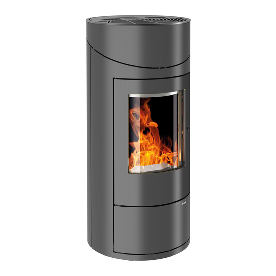
1. Technical data HSP 7 450.08 Heat output range 2,4-8,1 kW Nominal heat output 8 kW Height 1051 mm Width 490 mm Depth: 489 mm Weight 121 kg Diameter flue gas nozzle: 80 mm Flue gas temperature at nozzle 196°C... -
Page 6: Dimensional Drawing
2. Dimensional drawing... -
Page 7: Cleaning Of The Surface
3. Cleaning operations WARNING Before the start of cleaning operations, the stove must have cooled down! After finishing cleaning operations, the proper operation mode of the unit needs to be reestablished: proper insertion of the burner, closing of the furnace door. 3.1. -
Page 8: Cleaning Of The Ash Bin - Min. Weekly
3.5. Cleaning of the ash bin - min. weekly During weekly cleaning, the ash bin needs to be emptied. Figure: open door, push handle up, and pull out the ash bin. WARNING If this is not done, more and more slag accumulates. The stove can no longer ignite properly. Pellets can accumulate inside the burner. -
Page 9: Service Operations
4. Maintenance works WARNING For maintenance operations, the power plug needs to be disconnected from the socket. The maintenance frequency depends very much on the pellet quality (ash content). Quality pellets have a low ash content of approximately 0.2-0.3%. If the ash content is higher (0.5% and more), the interval between maintenances is reduced and the accumulation of ashes increases two - threefold. -
Page 10: Cleaning Of The Hot Gas Flues
4.2. Cleaning of the hot gas flues NOTE We also recommend checking resp. cleaning the hot gas flues at the latest after 1000 kg pellets. For cleaning the gas flues, proceed as follows: • Lift the draught deflection. You can now remove the draught deflection and the upper area of the combustion chamber can be cleaned (see Fig. -
Page 11: Disassembly Of The Cleaning Cover
4.3.1. Removing the cleaning cover Figure 11: Removing the cleaning cover 1 Screws 2 Cleaning cover Figure 12: Removing the cleaning cover 1 Screws 2 Right side wall 3 Nuts 4 Cleaning cover 5 Seal for cleaning cover... -
Page 12: Disassembly Of The Turbulator
4.3.2. Removing the turbulator Figure 13: Removing the convection air grate 1 Tank cap 2 Screws 3 Convection air grate Figure 14: Disassembly of the furnace cover 1 Screws Baffle plate left 3 Screws 4 Furnace cover... - Page 13 Figure 15: shake the turbulator 1 Turbulator The following tools are needed for the removal: • Phillips screwdriver • Wrench: 7 mm/ 8 mm/ 10 mm/ 13 NOTE When cleaning is completed, make sure that you place the seals in the right position when remounting the covers.
-
Page 14: Cleaning Of The Induced Draught Casing
4.3.3. Cleaning of the induced draught casing NOTE The induced draught casing can also be cleaned after removing the smoke pipes from the back side of the stove. In case of deposits / grinding noises in the induced draught casing, please proceed as follows: •... -
Page 16: Spare Parts List
5. Spare parts overview 5.1. Complete list HSP 7 450.08... - Page 17 Item Position Pieces Spare part number Comprehensive list HSP 7 450.08 Furnace door complete / pearl-black 1 pc 0545008005300 Handle tank cap LUCCA/CATANIA 440/441.08 2 pcs 0545008007581 Tank cap / pearl-black 1 pc 0545008006309 1 pc 0571207005510 Control unit / display...
-
Page 18: Detail A1
Spare part number List A1 Door screw connection set A1.1. 1 pc 0545008005221 Glass holder - Set A1.2. 1 pc 0545008005222 Furnace door 1 pc Seal glass 8x4 mm 1400 mm 0545008005223 Door glass window HSP 7 1 pcs 0545008005309... -
Page 19: Circuit Diagram
Description wiring harness Power plug/ mains filter Electric ignition Auger Induced draught 8. IX Safety temperature control CONV.FAN THS30B5/TFA745-S 5-PT160 HSP 7 35/36 Flue gas temperature sensor 37/38 Flame temperature sensor 39/40 Room temperature sensor 41/42 Flame temperature sensor bottom...
Need help?
Do you have a question about the HSP 7 and is the answer not in the manual?
Questions and answers