Table of Contents
Advertisement
Available languages
Available languages
Quick Links
Advertisement
Chapters
Table of Contents

Related Manuals for Larius OMEGA 5:1


Summary of Contents for Larius OMEGA 5:1
- Page 1 . l a r i u s . c o m OMEGA 5:1 Pompa pneumatica airless per estrusione OMEGA 5:1 pagina 2 http://www.larius.org/manuali/OMEGA_5_1_IT.pdf OMEGA 5:1 page 36 http://www.larius.org/manuali/OMEGA_5_1_UK.pdf...
-
Page 2: Table Of Contents
QUESTA APPARECCHIATURA É AD USO ESCLUSIVAMENTE PROFESSIONALE. NON É PREVISTA PER UN UTILIZZO DIVERSO DA QUELLO DESCRITTO IN QUESTO MANUALE. Grazie per aver scelto un prodotto LARIUS S.R.L. Unitamente all'articolo acquistato riceverete una gamma di servizi di assistenza per consentirVi di raggiungere i risultati desiderati, velocemente ed in modo professionale. -
Page 3: Aavvertenze
OMEGA 5:1 IT IT AVVERTENZE Nella tabella rappresentata di seguito viene descritto il significato dei simboli che sono presenti in questo manuale, che riguardano l’utilizzo, la messa a terra, le operazioni di utilizzo, manutenzione e riparazione di quest’apparecchiatura. • Leggere attentamente questo manuale prima di usare l’apparecchiatura. -
Page 4: Btrasporto E Disimballaggio
Qualora si riscontrassero componenti danneggiati, contattare • TENERE IN ORDINE L’AREA DI LAVORO. DISORDINE SUL POSTO tempestivamente la LARIUS e l’Agente di trasporto. Il termine DI LAVORO COMPORTA PERICOLO DI INCIDENTI. massimo per le comunicazioni di danneggiamento è di 8 giorni dalla data di ricevimento dell’apparecchiatura. - Page 5 OMEGA 5:1 IT IT • STRINGERE E CONTROLLARE TUTTI I RACCORDI DI COLLEGAMENTO TRA LA POMPA, IL TUBO FLESSIBILE E LA PISTOLA PRIMA DI UTILIZZARE L’APPARECCHIATURA. Verificare sempre la compatibilità del prodotto • UTILIZZARE SEMPRE IL TUBO FLESSIBILE PREVISTO NEL con i materiali che compongono l’apparecchiatura...
-
Page 6: Eprincipio Di Funzionamento
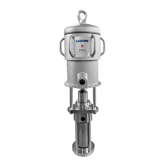
OMEGA 5:1 PRINCIPIO DI FUNZIONAMENTO La pompa OMEGA 5:1 è una pompa pneumatica ad alta pressione da utilizzare per l’estrusione e il trasferimento di prodotti ad alta viscosità. OMEGA è essenzialmente costituita da un motore ad aria e da una struttura definita “gruppo pompaggio materiale” o più semplicemente “gruppo pompante”. -
Page 7: Fdati Tecnici
OMEGA 5:1 IT IT DATI TECNICI Parti della pompa a contatto del materiale: OMEGA 5:1 Gruppo pompante: acciaio al carbonio zincato e ghisa o acciaio inox AISI 303 E 420B Pressione aria alimentazione pompa 3-6 bar / 40-120 psi Sfere di tenuta: acciaio inox AISI 420B Max. -
Page 8: Gdescrizione Dell'apparecchiatura
IT IT OMEGA 5:1 DESCRIZIONE DELL’APPARECCHIATURA ENTRATA ARIA USCITA MATERIALE ENTRATA MATERIALE Fig. 1G Pos. Descrizione Pos. Descrizione Motore pneumatico Messa a terra Ghiera premiguarnizione porta lubrificante Uscita materiale Gruppo pompante materiale Entrata materiale Ingresso aria di alimentazione pompa www.larius.com... -
Page 9: Hinstallazione Tipica
IT IT INSTALLAZIONE TIPICA La pompa OMEGA 5:1 viene solitamente fornita già fissata su staffa per il fissaggio a parete oppure su carrello o su paranco pneumatico. Per il corretto fissaggio della pompa su altre strutture utilizzare i 4 fori posti sulla base del motore pneumatico ( (vedi figura per quote dimensionali). -
Page 10: Isistema Antigelo
IT IT OMEGA 5:1 SISTEMA ANTIGELO La macchina é provvista di un sistema anti-gelo che le consente di lavorare anche a temperature molto basse. Tuttavia la superficie esterna metallica superiore dopo alcuni minuti di funzionamento si raffredda in modo consistente. Evitare di toccare la zona indicata. -
Page 11: Kfunzionamento
OMEGA 5:1 IT IT FUNZIONAMENTO • La pompa è stata collaudata in fabbrica con olio minerale Controllare tutti i raccordi di collegamento dei diversi leggero che può essere rimasto in parte all’interno del componenti (pompa, tubo flessibile, pistola, ecc.) pompante. Puntare la pistola o la valvola erogatrice contro prima di utilizzare l’apparecchiatura. -
Page 12: Mmanutenzione Ordinaria
IT IT OMEGA 5:1 • Continuando a spruzzare, sollevare il tubo di aspirazione (1) e di ricircolo (2), in modo da scaricare tutto il solvente. Fermare quindi la pompa chiudendo il rubinetto dell’aria. • Dopo il lavaggio se si prevede un lungo periodo di inattività... -
Page 13: Nsmontaggio Del Motore Pneumatico
OMEGA 5:1 IT IT SMONTAGGIO DEL MOTORE • Svitare le due ghiere (6) dal supporto (7). Chiudere sempre la fornitura di aria compressa e scaricare la pressione prima di procedere allo • Svitare le viti (8) [attenzione alle rondelle (9)] e sfilare il supporto (7) assieme ai rulli (10) e alle spine (11). - Page 14 IT IT OMEGA 5:1 • Tirare verso l’alto l’alloggiamento (17) così da poter togliere le valvole (18), gli anelli OR (19) e le molle (20) (pulire e/o sostituire i particolari usurati). • Svitare il controdado (21) [attenzione alla rondella (22)] tenendo bloccata con una chiave la bussola (23).
- Page 15 OMEGA 5:1 IT IT • Svitare la vite guida asta (31) [attenzione alla rondella (32)] e verificare che la guarnizione di tenuta all’interno della vite (31) non sia rovinata. • Togliere le viti (33) [attenzione alle rondelle (34) ] e rimuovere...
- Page 16 IT IT OMEGA 5:1 • Verificare l’integrità dell’anello di tenuta all’interno del supporto (40). • Controllare l’integrità e l’esatto posizionamento della guarnizione (41). • Stendere un leggero velo di grasso di vaselina sulle pareti interne del cilindro (42). • Inserire con molta cautela il pistone motore (43) nel cilindro (42).
- Page 17 OMEGA 5:1 IT IT • Inserire nell’alloggiamento (54) le molle (55) e le valvole (56), posizionare l’alloggiamento sul supporto pompa e appoggiare contro l’alloggiamento il collettore (57) [ricordarsi della guarnizione (58)]. • Fissare il collettore con le viti (non stringere eccessivamente per il momento) assicurandosi che esso risulti perfettamente parallelo all’altro collettore e che la distanza tra i due...
-
Page 18: Osmontaggio Del Gruppo Pompante
IT IT OMEGA 5:1 SMONTAGGIO DEL GRUPPO POMPANTE Chiudere sempre la fornitura di aria compressa e scaricare la pressione prima di procedere allo smontaggio del gruppo pompante. • Svitare i 3 dadi M16 (1). Fig. 1O • Svitare il manicotto di congiunzione (2) tenendo fermo con una controchiave (4) il dado (3). - Page 19 OMEGA 5:1 IT IT • Togliere il manicotto di congiunzione (2) dal resto del pompante. • Allentare i quattro tiranti (5). • Verificare l’integrità e provvedere alla pulizia degli elementi smontati. Nel caso di usura, é necessario provvedere alla sostituzione degli stessi.
- Page 20 IT IT OMEGA 5:1 Il pompante smontato a questo punto risulta composto wdai seguenti componenti: • la flangia superiore (6) • il pistone completo (7) • il cilindro (8) • la vavola di fondo (9) Fig. 3O www.larius.com ED. 01 - 09/2022 - Cod. 150206...
- Page 21 OMEGA 5:1 IT IT SOSTITUZIONI GUARNIZIONI SUPERIORI • Sfilare le guarnizioni (11), (12), (13), (14). dall’alloggio • Verificare e provvedere alla pulizia dell’alloggio guarnizioni garnizioni superiori (10) e sostituirle con quelle nuove. (10). Nel caso di usura, é necessario provvedere alla sostituzione dello stesso.
- Page 22 IT IT OMEGA 5:1 SOSTITUZIONI GUARNIZIONI INFERIORI • Svitare le quattro viti (17). • Rimuovere le due guarnizioni in rame (15) e (18) e sostituirle con quelle nuove. • Togliere le due guarnizioni (16) inferiori del pistone e sostituirle con quelle nuove.
-
Page 23: Pinconvenienti E Rimedi
OMEGA 5:1 IT IT INCONVENIENTI E RIMEDI Inconveniente Causa Soluzione La pompa non entra in funzione L’aria di alimentazione è insufficiente; Controllare la linea di fornitura dell’aria. Aumentare il diametro del tubo di alimentazione; Linea di uscita del prodotto intasata;... -
Page 24: Qricambi Gruppo Motore
IT IT OMEGA 5:1 RICAMBI GRUPPO MOTORE ATTENZIONE: per ogni particolare richiesto indicare sempre il codice e la quantità. www.larius.com ED. 01 - 09/2022 - Cod. 150206... - Page 25 OMEGA 5:1 IT IT Pos. Code Description Q.ty Pos. Code Description Q.ty 96210 Targhetta “Messa a terra” 7118 Targa OMEGA 95062 Vite 95109 Supporto 95063 Rondella 95085 Guida molla 7113 Copertura 95084 Pistone spingi rullo 19555 Adesivo “Atex” 95087 Ghiera...
-
Page 26: Rkit Elenco Ricambi Gruppo Motore
IT IT OMEGA 5:1 KIT ELENCO RICAMBI GRUPPO MOTORE ATTENZIONE: per ogni particolare richiesto indicare sempre il codice e la quantità. www.larius.com ED. 01 - 09/2022 - Cod. 150206... - Page 27 OMEGA 5:1 IT IT Cod. KIT 40345 Guarnizioni motore Cod. KIT 40066 Scambio motore Pos. Descrizione Q.tà Pos. Descrizione Q.tà Pistone spingi rullo Guarnizione collettore Valvola inversione corsa pistone Rullo Anello O-ring Dado Valvola inversione corsa Rondella in rame Anello di supporto per guarnizione...
-
Page 28: Sricambi Gruppo Pompante
IT IT OMEGA 5:1 RICAMBI GRUPPO POMPANTE ATTENZIONE: per ogni particolare richiesto indicare sempre il codice e la quantità. www.larius.com ED. 01 - 09/2022 - Cod. 150206... - Page 29 OMEGA 5:1 IT IT Pos. Codice Descrizione Q. tà Pos. Codice Descrizione Q. tà 95621 Tirante Tappo 95102/2 Tubo del pistone 95654 Guarnizione in rame 95104/1 Raccordo 98118 Tappo inferiore pistone 95003 Riduzione 95650 Guarnizione PTFE 95004 Manicotto di congiunzione 95027 Sfera 1”...
-
Page 30: Tkit Elenco Ricambi Gruppo Pompante
IT IT OMEGA 5:1 KIT ELENCO RICAMBI GRUPPO POMPANTE ATTENZIONE: per ogni particolare richiesto indicare sempre il codice e la quantità. www.larius.com ED. 01 - 09/2022 - Cod. 150206... - Page 31 OMEGA 5:1 IT IT Cod. KIT 40304 Guarnizioni pompante Cod. KIT 40305 Valvola di mandata Pos. Descrizione Q.tà Pos. Descrizione Q.tà Copiglia Guarnizione in rame Guarnizione femmina Guarnizione PTFE Guarnizione PTFE Sfera Guarnizione in cuoio Sede sfera valvola superiore +...
-
Page 32: Ucertificazione Atex
Queste istruzioni di sicurezza si riferiscono all’installazione, uso e manutenzione delle pompe pneumatiche a pistone per travaso LARIUS serie OMEGA per l’utilizzo in aree potenzialmente esplosive con presenza di gas o vapori. Le pompe pompe pneumatiche a pistone LARIUS Queste istruzioni devono essere osservate in serie OMEGA sono apparecchiature meccaniche aggiunta alle avvertenze riportate nel manuale del gruppo II, per l’uso in zone classificate con... - Page 33 OMEGA 5:1 IT IT ISTRUZIONI DI SICUREZZA PER L’INSTALLAZIONE IN ZONA PERICOLOSA Prima dell’installazione leggere attentamente quanto riportato nel manuale d’uso e manutenzione. Tutte le operazioni di manutenzione devono essere eseguite secondo quanto riportato nel manuale. • Il cavo di M.T. delle suddette pompe deve essere collegato a terra mediante apposito elemento di connessione antiallentante.
- Page 34 IT IT OMEGA 5:1 www.larius.com ED. 01 - 09/2022 - Cod. 150206...
-
Page 35: Dichiarazione Di Conformita
OMEGA 5:1 IT IT DICHIARAZIONE DI CONFORMITA’ Il fabbricante LARIUS srl Via Antonio Stoppani 21 - 23801 Calolziocorte (LC) ITALY Tel: +39 0341 621152 Fax: +39 0341 621243 E-mail: larius@larius.com Dichiara sotto la propria responsabilità che il prodotto: OMEGA 5:1 Pompa pneumatica airless per estrusione è... - Page 36 WE ADVISE THE USE OF THIS EQUIPMENT ONLY BY PROFESSIONAL OPERATORS. ONLY USE THIS MACHINE FOR USAGE SPECIFICALLY MENTIONED IN THIS MANUAL. Thank you for choosing a LARIUS S.R.L. product. As well as the product purchased, you will receive a range of support services enabling you to achieve the results desired, quickly and professionally.
-
Page 37: Awarnings
OMEGA 5:1 IT IT WARNINGS The table below provides the meaning of the symbols used in this manual in relation to using, earthing, operating, maintaining, and repairing of this equipment. • Read this operator’s manual carefully before using the equipment. -
Page 38: Btransport And Unpacking
Check the packing is undamaged on receipt of the equipment. Unpack the machine and verify if there has been any damage due to transportation. In case of damage, call immediately LARIUS and the Shipping Agent. • KEEP YOUR WORK PLACE CLEAN AND TIDY. DISORDER... - Page 39 OMEGA 5:1 IT EN • (IF PROVIDED) TIGHTEN AND CHECK ALL THE FITTINGS FOR Never spray over flammable products or solvents CONNECTION BETwEEN PUMP, FLEXIBLE HOSE AND SPRAY in closed places. GUN BEFORE USING THE EQUIPMENT. Never use the tooling in presence of potentially •...
-
Page 40: Eworking Principle
WORKING PRINCIPLE Nova pump OMEGA 5:1 is a high pressure pneumatic pump used for extrusion and transferring of high viscosity products. OMEGA pump is essentially constituted of an air motor and a structure called «material pumping group» or simply «pumping group». -
Page 41: Ftechnical Data
OMEGA 5:1 IT EN TECHNICAL DATA Parts of the pumpt in contact with the material: OMEGA 5:1 Pumping group: Galvanized carbon steel and cast iron or stainless steel AISI 303 and 420B Pump feed air pressure 3-6 bar / 40-120 psi... -
Page 42: Gdescription Of The Equipment
IT EN OMEGA 5:1 DESCRIPTION OF THE EQUIPMENT IN AIR MATERIAL OUTLET MATERIAL INLET Fig. 1G Pos. Description Pos. Description Grounding electric cable Pneumatic motor Ring gasket press for lubricant Material outlet Pumping group Material inlet Pump feed air inlet Fig. -
Page 43: Htypical Installation
TYPICAL INSTALLATION The OMEGA 5:1 pump is generally supplied on support for wall fastening or on trolley or on double post ram. For the correct fastening of the pump on other structures use the 4 holes placed at the base of the pneumatic motor (See the illustration for dimensions). -
Page 44: Iantifreeze System
IT EN OMEGA 5:1 ANTIFREEZE SYSTEM The machine is equipped with an anti-freeze system that allows it to work even at very low temperatures. However, after a few minutes of operation, the upper metal outer surface cools dramatically. Avoid touching the area indicated. -
Page 45: Kworking
OMEGA 5:1 IT EN WORKING • The pump has been adjusted at our factory with light mineral Check all the fittings for connection of the different oil and a part of it could be left inside the pumping element. components (pump, flexible hose, spray gun, etc.) Point the spray gun or the delivery valve at the tank and before using the equipment. -
Page 46: Mgeneral Maintenaince
IT EN OMEGA 5:1 • By going on spraying, lift the suction (1) and the recirculation hoses (2), in order to drain out all the thinner. Then stop the pump, by closing the air tap. • After washing, in case a long period of downtime is foreseen... -
Page 47: Ndisassembly Of The Pneumatic Motor
OMEGA 5:1 IT EN DISASSEMBLY OF THE PNEUMATIC MOTOR • Unscrew the two ring nuts (6) from the support (7). Always close the compressed air supply and release the pressure in the plant before disassembling the • Turn counterclockwise the screws (8) [take care to the washers (9)] and remove the support (7) together with pneumatic group. - Page 48 IT EN OMEGA 5:1 • Pull upwards the seat (17) so as to take out the valves (18), the O-rings (19) and the springs (20) (clean and/or replace the worn parts). • Unscrew the lock nut (21) [take care of the washer (22)] by keeping the bush (23) blocked using a wrench.
- Page 49 OMEGA 5:1 IT EN • Turn counterclockwise the rod guiding screw (31) [take care to the washer (32)] and check the seal inside the screw (31) is undamaged. • Take out the screws (33) [take care of the washers (34)]...
- Page 50 IT EN OMEGA 5:1 • Check the gas ring inside the support (40) is undamaged. • Check the gasket (41) is undamaged and correctly positioned. • Coat the inner walls of the cylinder (42) with a thin layer of vaseline grease.
- Page 51 OMEGA 5:1 IT EN • Insert the springs (55) and the valves (56) into the seat (54). Position the seat on the pump support and lay the manifold (57) on the seat [do not forget the gasket (58)]. • Fasten the manifold with screws (do not tighten) ensuring it is perfectly parallel to the other manifold and the distance between them is 46 mm (see illustration).
-
Page 52: Disassembly Of The Pumping Group
IT EN OMEGA 5:1 DISASSEMBLY OF THE PUMPING GROUP O O O Always close the compressed air supply and release the pressure in the plant before disassembling the pumping group. • Unscrew the 3 nuts M16 (1). Fig. 1O •... - Page 53 OMEGA 5:1 IT EN • Remove the sleeve (2) from the rest of the pump. • Loosen the four tie rods (5). • Check the integrity and clean the disassembled elements. In case of wear, it is necessary to replace them.
- Page 54 IT EN OMEGA 5:1 The disassembled pumping group is now composed from the following components: • the upper flange (6) • the complete piston (7) • the cylinder (8) • the foot valve (9) Fig. 3O www.larius.com ED. 01 - 09/2022 - Cod. 150206...
- Page 55 OMEGA 5:1 IT EN UPPER GASKETS REPLACEMENTS • Extract the gaskets (11), (12), (13), (14). from the upper • Check and clean the gasket housing (10). In case of wear, gasket housing (10) and replace them with new ones. it is necessary to replace it.
- Page 56 IT EN OMEGA 5:1 LOWER GASKETS REPLACEMENTS • Unscrew the four nuts (17). • Remove the two copper gasket (15) and (18)and replace them with new ones. • Remove the two lower piston gaskets (16) and replace them with new ones.
-
Page 57: Ptroubleshhoting
TROUBLESHOOTING Problem Possible cause Solution The pump does not start Feeding air is not enough; Check the air supply. Increase the diameter of the feeding hose; Outlet product line clogged; Clean. Disconnect the outlet product pipe. Feed pump at minimum pressure and check if the pump starts without the outlet pipe;... -
Page 58: Qmotor Group Spare Parts
IT EN OMEGA 5:1 MOTOR GROUP SPARE PARTS ATTENTION: always indicate code and quantity of each requested detail www.larius.com ED. 01 - 09/2022 - Cod. 150206... - Page 59 OMEGA 5:1 IT EN Pos. Code Description Q. ty Pos. Code Description Q. ty 96210 Grounding plate 7118 Plate OMEGA 95062 Screw 95109 Support 95063 washer 95085 Spring guide 7113 Covering 95084 Roller pushing piston 19555 Atex plate 95087 Ring nut...
-
Page 60: Rmotor Group Spare Parts Kit
IT EN OMEGA 5:1 MOTOR GROUP SPARE PARTS KIT ATTENTION: always indicate code and quantity of each requested detail www.larius.com ED. 01 - 09/2022 - Cod. 150206... - Page 61 OMEGA 5:1 IT EN Code 40345 Motor gasket KIT Code 40066 Motor movement inversion device KIT Pos. Description Q.ty Pos. Description Q.ty Manifold gasket Roller pushing piston Inversion movement valve Roller O-ring Copper washer Inversion movement valve Support ring O-ring...
-
Page 62: Spumping Group Spare Parts
IT EN OMEGA 5:1 PUMPING GROUP SPARE PARTS ATTENTION: always indicate code and quantity of each requested detail www.larius.com ED. 01 - 09/2022 - Cod. 150206... - Page 63 OMEGA 5:1 IT EN Pos. Code Description Q. ty Pos. Code Description Q. ty 95621 Tie rod Plug 95102/2 Piston tube 95654 Copper gasket 95104/1 Fitting 98118 Lower piston plug 95003 Bush 95650 Gasket PTFE 95004 Sleeve 95027 Ball 1” 1/4...
-
Page 64: Tpumping Group Spare Parts Kit
IT EN OMEGA 5:1 PUMPING GROUP SPARE PARTS KIT ATTENTION: always indicate code and quantity of each requested detail www.larius.com ED. 01 - 09/2022 - Cod. 150206... - Page 65 OMEGA 5:1 IT EN Code KIT 40304 Pump gasket kit Cod. KIT 40305 Valve kit Pos. Description Q.ty Pos. Description Q.ty Split pin Copper gasket Female gasket Gasket PTFE Gasket PTFE Ball 1” 1/4 Leather gasket Housing seat bal + Fitting...
-
Page 66: Uatex Certificate
LARIUS piston pneumatic transfer pumps OMEGA These instructions should be followed in addition series are mechanical equipment belonging to to the instructions provided in the use and group II, for the use in areas in presence of maintenance manual. - Page 67 OMEGA 5:1 IT EN SAFETY INSTRUCTIONS FOR THE INSTALLATION IN DANGEROUS AREAS Before installation please read carefully the use and maintenance manual. All maintenance operations must be carried out as reported in the manual. • The grounding cable of these pumps must be connected by means of suitable electrical connector.
- Page 68 IT EN OMEGA 5:1 www.larius.com ED. 01 - 09/2022 - Cod. 150206...
-
Page 69: Declaration Of Conformity
OMEGA 5:1 IT EN CE DECLARATION OF CONFORMITY Company LARIUS srl Via Antonio Stoppani 21 - 23801 Calolziocorte (LC) ITALY Tel: +39 0341 621152 Fax: +39 0341 621243 E-mail: larius@larius.com Declares under his owns resonsibility that the product: OMEGA 5:1... - Page 70 OPERATING AND MAINTENAINCE MANUAL AVAILABLE IN: http://www.larius.org/manuali/OMEGA_5_1_IT.pdf http://www.larius.org/manuali/OMEGA_5_1_UK.pdf LARIUS srl Via Antonio Stoppani 21 - 23801 Calolziocorte (LC) ITALY TEL. +39 0341 621152 - Fax +39 0341 621243 - larius@larius.com www.larius.com...
Need help?
Do you have a question about the OMEGA 5:1 and is the answer not in the manual?
Questions and answers