Salus Controls DT300, DT300RF - Digital Room Thermostat Quick Guide
- Quick manual (7 pages)
Advertisement
- 1 Introduction
- 2 Safety Information
- 3 Technical specification
- 4 Button functions
- 5 LCD Icon description
- 6 DT300 Thermostat terminals description
- 7 DTRX3 Receiver terminals description
- 8 DT300 Thermostat Wiring Diagram
- 9 DT300RF Thermostat Wiring Diagram
- 10 Change the Setpoint temperature
- 11 Frost Protection
- 12 Sleep Mode
- 13 Pairing the DT300RF Thermostat with the DTRX3 Receiver
- 14 Installer Mode
- 15 Battery replacement
- 16 Reset of the DT300/DT300RF thermostat
- 17 Product compliance
- 18 Documents / Resources
Introduction
DT300/DT300RF is a digital room thermostat used to control room temperature. Device launching heating system by shorting terminal blocks, simultaneously informing the action and showing this information on the LCD display. Before use please read this manual carefully. Use only AA 1. 5 V alkaline batteries in the thermostat. Place the batteries into the battery holder located on the side of thermostat (see the Battery Replacement chapter). Do not use rechargeable batteries.
Safety Information
 Use in accordance to national and EU regulations. Use the device as intended, keeping it in dry condition. Product for indoor use only. Installation must be carried out by a qualified person in accordance to national and EU regulations.
Technical specification
| DT300 Thermostat | DT300RF Thermostat | |
| Thermostat supply | 2 x AA alkaline batteries | 2 x AA alkaline batteries |
| Receiver supply | - | 230 V AC |
| Thermostat rating max | 5 (3) A | - |
| Receiver rating max | - | 16 (5) A |
| Outputs | Voltage free NC / NO / COM terminals | - |
| Temperature range | 5 - 35°C | 5 - 35°C |
| Dimension [mm] | 90 x 90 x 29 | 90 x 90 x 29 |
Button functions

- Turn on the LCD backlight
- Turn On/Off the Frost Mode
- Increase button
- Decrease button
- When in manual mode, ON will turn the boiler on. When in manual mode, OFF will turn the boiler off.
- Receiver operates in automatic mode according to the thermostat/Receiver output is controlled by the On/Off slide switch.
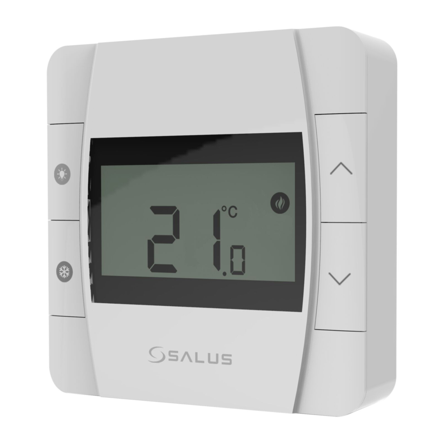
LCD Icon description
![]()
- Heating Mode ON
- Frost Protection Mode ON
- RF signal indicator (only for DT300RF)
- Low battery status
- Temperature unit
- Room / setpoint temperature
DT300 Thermostat terminals description

| Terminal | Description |
| 1 - COM | Common Terminal |
| 2 - NC | Switched Live OFF |
| 3 - NO | Switched Live ON |
DTRX3 Receiver terminals description

| Terminal | Description |
| NO | Switch Terminal |
| COM | Common Switch Terminal |
| L, N | Power Supply (230 V AC) |
DT300 Thermostat Wiring Diagram

DT300RF Thermostat Wiring Diagram

Legend:
 Boiler - Boiler connection*
- Boiler's contacts for ON / OFF thermostat (according to the boiler's instructions)
 Pump
Pump
 Valve actuator
Symbols explanation:
L, N - Power supply 230V
NO, COM, NC - Voltage-free output
 - Fuse
Change the Setpoint temperature

The thermostat displays measured room temperature. → Press  or
or  , to set the temperature.
After 2 seconds, the new temperature setpoint will be overwritten. → The thermostat will display the measured temperature again. The heating mode icon will appear if the temperature setpoint is higher than the measured temperature.
Frost Protection

Press  button to turn ON/OFF frost protection. → When the snowflake icon is displayed then it means that the frost protection mode is active.
 The Frostpoint temperature can be reviewed by pressing the
 ![]() button once, but can only be changed in Installer Mode.
button once, but can only be changed in Installer Mode.
Sleep Mode
When Sleep Mode is active all the thermostat functions will be paused.

To enter sleep mode, press and hold and for 3 seconds. → To exit sleep mode, press twice any button.
Pairing the DT300RF Thermostat with the DTRX3 Receiver
Note: If you are using the DT300RF pack, the pairing between the thermostat and the receivers already done. During the pairing process, please make sure the thermostat and the receiver are at least 1 meter from each other.
Important note: The communication radius of the thermostat with the receiver is of maximum 100m, in open space. In built space, with various obstacles (eg walls, floors, metal structures, furniture elements), the communication radius will be significantly reduced. RF communication can be disrupted by local factors, such as GSM antennas, radio frequency devices or toys, or other equipment that produces electromagnetic interference. Receivers for the boiler must be powered from a stable voltage source, without frequent interruptions or voltage fluctuations (outside the standard tolerance). The manufacturer is not responsible for identifying or combating the effects of local disturbances.
If you want to re-pair the devices with each other, follow the steps below:
- Make sure that the receiver is disconnected from the power supply and the switches on it are in the AUTO and ON positions. Then connect the receiver to the power supply and wait for the green LED to glow continuously.
![]()
- Move the left switch to the OFF position with a quick motion and back to the ON position
![]()
- The green LED will start blinking, which will confirm that the receiver has entered the pairing mode
![]()
- Press and hold PAIRING / TEST button behind the back cover cover for 3 seconds.

![]()
- When the thermostat enters sync mode, the screen will display S Y + a digit. The pairing process can take up to 9 minutes. Once devices are successfully paired, the LED indicator will turn permanently green.

- Press and hold PAIRING / TEST button behind the back cover cover for 3 seconds.

![]()


Installer Mode

Press three buttons at the same time for 3 seconds → Press  to edit the parameter. To change the parameter value use
 ![]() and
and ![]() buttons.
buttons.
To exit Installer Mode, wait 10 seconds, the thermostat will automatically return to the main screen.
| dxx | Function | Parameter value | Default value |
| d01 | Temperature display increments | 0.1°C or 0.5°C | 0.5°C |
| d02 | Temperature offset | +/- 3.0°C | 0.0°C |
| d03 | Frost protection setpoint temperature | 5.0°C - 17.0°C | 5.0°C |
| d04 | TPI or SPAN algorithm selection TPI = self-adaptive algorithm SPAN = hysteresis (fixed temperature deviation) | TPI or SPAN | TPI |
| d05 | TPI or SPAN adjustment (if you selected SPAN in parameter d04, then parameter d05 will display the SPAN settings, the same applies to the TPI algorithm) | 6CP or 9CP / 0.25°C or 0.5°C | 6CP / 0.5°C |
Battery replacement

To insert and replace the batteries, follow the steps below:
- Unlock the battery compartment.
- Push the battery holder at the bottom of the thermostat
- After adding or replacing the batteries, re-insert the battery holder.
Reset of the DT300/DT300RF thermostat

Press the RESET button under the back cover (you can use a paper clip), the thermostat will reset and restart automatically.
Product compliance
This product complies with the essential requirements and other relevant provisions of Directives EMC 2014/30/EU, LVD 2014/35/EU, RED 2014/53/EU and RoHS 2011/65/EU. The full text of the EU Declaration of Conformity is available at the following internet address: www.saluslegal.com
SALUS Controls
Units 8-10, Northfield Business Park
Forge Way, Parkgate,
Rotherham, S60 1SD
Email: sales@salus-tech.com

SALUS Controls is a member of the Computime Group.
Maintaining a policy of continuous product development SALUS Controls plc reserve the right to change specification, design and materials of products listed in this brochure without prior notice.
Issue Date: May 2022
V03


Documents / Resources
References
Download manual
Here you can download full pdf version of manual, it may contain additional safety instructions, warranty information, FCC rules, etc.
Download Salus Controls DT300, DT300RF - Digital Room Thermostat Quick Guide
Advertisement


Need help?
Do you have a question about the DT300 and is the answer not in the manual?
Questions and answers