Waterous CM Series Overhaul Instructions
Fire pumps
Hide thumbs
Also See for CM Series:
- Overhaul instructions (61 pages) ,
- Installation manual (56 pages) ,
- Operation and maintenance manua (28 pages)

Related Manuals for Waterous CM Series


Summary of Contents for Waterous CM Series
- Page 1 Form Number: F-3005 Issue Date: Feb 6, 2023 CM Series Fire Pumps Overhaul Instructions Waterous Company • 125 Hardman Avenue South • South Saint Paul, MN 55075 • (651) 450-5000 www.waterousco.com...
-
Page 3: Table Of Contents
Table of Contents Safety Assembly Safety Precautions Preparing to Assemble the Pump Tools Required Introduction Best Practices Using this Document Optional Equipment Viewing the Document Electronically Assembling the Pump Components Printing the Document Installing the Pump Symbols Understanding the Illustrations Identifying Exterior Components—Rear Retaining Ring Installation Tool Identifying Exterior Components—Front... -
Page 4: Safety
• Hot surfaces can burn you. • Do not modify the equipment. • Do not touch the surface • Waterous reserves the right to make modifications to the instructions without during operation—allow notice. it to cool after operating. -
Page 5: Introduction
Disassembly Assembly Symbols Use this document to overhaul your Waterous equipment. Please understand the following conditions: Symbols are used to illustrate additional tools or operations that are required to • Be aware that these instructions are only guidelines and are not meant to be complete the instruction. -
Page 6: Identifying Exterior Components-Rear
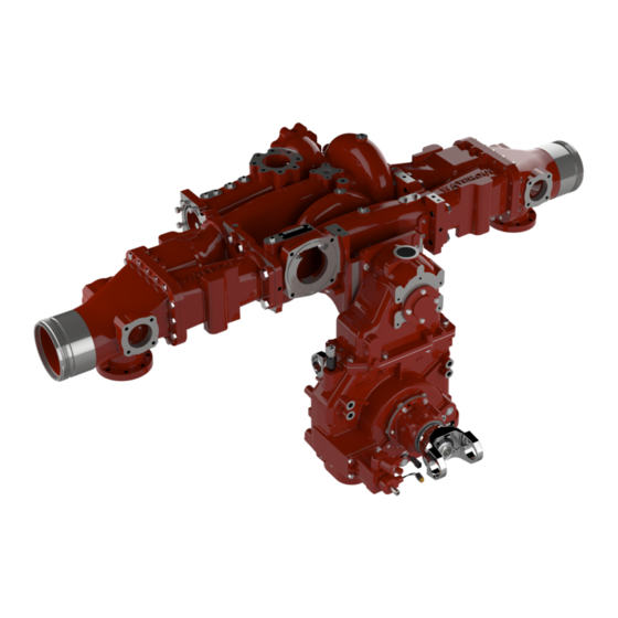
Safety Introduction Disassembly Assembly Identifying Exterior Components—Rear Use the illustration to identify various components on the pump. Pump body Intake adapter Tank intake adapter Oil cooling lines—optional Transmission mounting hardware Transmission—C22 shown Oil level plug Oil level sight plug Oil drain plug 6 | 70... -
Page 7: Identifying Exterior Components-Front
Safety Introduction Disassembly Assembly Identifying Exterior Components—Front Use the illustration to identify various components on the pump. Volute cover Seal cooling hose Transmission mounting hardware Bearing housing Transfer valve cover Breather Oil cooling lines—optional Oil cooler plate—optional 7 | 70... -
Page 8: Disassembly
• This equipment is intended to be disassembled by a person or persons with applications allow you to separate the pump without removing the transmission the basic knowledge of servicing similar equipment. Contact Waterous for from the apparatus. Refer to the transmission instructions before proceeding. -
Page 9: Packing Ring Removal Tool
Safety Introduction Disassembly Assembly Packing Ring Removal Tool An optional Packing Ring Removal Tool (5782) is available from Waterous to aid in removing the packing rings—dimensions shown in inches. 9 | 70... -
Page 10: Retaining Ring Removal Tool
Safety Introduction Disassembly Assembly Retaining Ring Removal Tool An optional Retaining Ring Removal Tool (62917) is available from Waterous to aid in removing the retaining rings—dimensions shown in inches. 10 | 70... -
Page 11: Removing The Seal Cooling Hose
Safety Introduction Disassembly Assembly Removing the Seal Cooling Hose Use the illustration and instructions to remove the seal cooling hose. Note: Only remove the hose if it needs to be replaced. Remove the hose from the fittings on the underside of the pump. 11 | 70... -
Page 12: Separating The Pump And Transmission
Safety Introduction Disassembly Assembly Separating the Pump and Transmission Use the illustration and instructions to separate the pump and transmission—C22 transmission shown. Note: Separating the pump and transmission is a similar process regardless of transmission model and mounting location. Remove the lower transmission mounting hardware. - Page 13 Safety Introduction Disassembly Assembly Separating the Pump and Transmission Use the illustration and instructions to separate the pump and transmission. Use locally sourced 1/2-13 jacking screws to separate the pump and transmission. Remove the transmission from the pump. 13 | 70...
- Page 14 Safety Introduction Disassembly Assembly Removing the Tank Intake Adapter Use the illustrations and instructions to remove the tank intake adapter. Note: The tank-to-pump fitting or valve may differ depending on your application. Remove the mounting hardware, then remove the tank intake adapter. Remove and discard the O-ring.
- Page 15 Safety Introduction Disassembly Assembly Removing the Intake Adapters Use the illustrations and instructions to remove the intake adapters. Note: Only remove the intake adapters if they or the pump body need to be replaced. Remove the flap valve, then remove the bearing from each end of the valve.
-
Page 16: Disassembling The Pump Body
Safety Introduction Disassembly Assembly Disassembling the Pump Body Use the illustration and instructions to disassemble the pump body. Remove the upper bearing housing hardware. Loosen, but do not remove, the lower bearing housing hardware. 16 | 70... - Page 17 Safety Introduction Disassembly Assembly Disassembling the Pump Body Use the illustrations and instructions to disassemble the pump body. Insert locally sourced 1/2-13 jacking screws into the volute cover jacking screw holes. Remove screws on both sides of the volute cover to accommodate the threaded rods. 17 | 70...
- Page 18 Safety Introduction Disassembly Assembly Disassembling the Pump Body Use the illustration and instructions to disassemble the pump body. To prepare the threaded rods to lower the volute cover, do the following: • Thread a spacer (6 inches), 2 washers, and a nut onto each rod (1/2-13 x 18 inches).
- Page 19 Safety Introduction Disassembly Assembly Disassembling the Pump Body Use the illustrations and instructions to disassemble the pump body. Tighten the jacking screws to separate the volute cover from the pump body, alternating between them to avoid damaging the dowel pins. Loosen the nuts on the rods, alternating between them to gradually lower the volute cover.
-
Page 20: Removing The Impeller Shaft Assembly
Safety Introduction Disassembly Assembly Removing the Impeller Shaft Assembly Use the illustrations and instructions to remove the impeller shaft assembly from the volute cover. Remove and discard the molded gaskets and O-rings. Remove the lower bearing housing hardware. Remove the impeller shaft assembly. 20 | 70... -
Page 21: Removing The Outboard Bearing Housing
Safety Introduction Disassembly Assembly Removing the Outboard Bearing Housing Use the illustrations and instructions to remove the outboard bearing housing. The tools being used are included in the Outboard Bearing Removal and Installation Kit (K 956). Note: Use the same method to remove the bearing housing when the impeller shaft assembly remains in the pump and only the mechanical seals are replaced. -
Page 22: Disassembling The Outboard Bearing Housing
Safety Introduction Disassembly Assembly Disassembling the Outboard Bearing Housing Use the illustrations and instructions to disassemble the outboard bearing housing. Remove the bearing shield. Remove the retaining ring. Remove the bearing. 22 | 70... -
Page 23: Disassembling The Impeller Shaft With Mechanical Seals
Safety Introduction Disassembly Assembly Disassembling the Impeller Shaft with Mechanical Seals Use the illustrations and instructions to disassemble the impeller shaft. Remove the retaining rings. Remove the seal housing hardware, then remove the seal housing cover. 23 | 70... - Page 24 Safety Introduction Disassembly Assembly Disassembling the Impeller Shaft with Mechanical Seals Use the illustrations and instructions to disassemble the impeller shaft. Remove the stationary ring. Remove the throttle bushing. Remove and discard the O-ring. Clean and lubricate the shaft, then pull on the seal housing to release the mechanical seal bellows.
- Page 25 Remove the wear ring. Remove the retaining ring. Note: An optional retaining ring removal tool (62917) is available from Waterous. 10 Press the impeller toward the center of the shaft to remove the lock ring. 11 Use an arbor press to remove the impeller.
- Page 26 Safety Introduction Disassembly Assembly Disassembling the Impeller Shaft with Mechanical Seals Use the illustrations and instructions to disassemble the impeller shaft. 13 Remove the seal housing hardware, then remove the seal housing cover. 14 Remove the stationary ring. 15 Remove the throttle bushing. 16 Remove and discard the O-ring.
- Page 27 Safety Introduction Disassembly Assembly Disassembling the Impeller Shaft with Mechanical Seals Use the illustrations and instructions to disassemble the impeller shaft. 17 Clean and lubricate the shaft, then pull on the seal housing to release the mechanical seal bellows. Remove the seal housing and mechanical seal.
- Page 28 Safety Introduction Disassembly Assembly Disassembling the Impeller Shaft with Mechanical Seals Use the illustrations and instructions to disassemble the impeller shaft. 17 Press the impeller toward the center of the shaft to remove the lock ring. 18 Use an arbor press to remove the impeller. 19 Remove the key.
-
Page 29: Disassembling The Impeller Shaft With Packing
Safety Introduction Disassembly Assembly Disassembling the Impeller Shaft with Packing Use the illustrations and instructions to disassemble the impeller shaft. Remove the retaining ring and V-ring seal. Remove the hardware and gland halves. 29 | 70... - Page 30 Note: An optional packing removal tool (5782) is available from Waterous. Remove and discard the seal housing gaskets. Remove the wear ring. Remove the retaining ring. Note: An optional retaining ring removal tool (62917) is available from Waterous. 30 | 70...
- Page 31 Safety Introduction Disassembly Assembly Disassembling the Impeller Shaft with Packing Use the illustrations and instructions to disassemble the impeller shaft. Press the impeller toward the center of the shaft to remove the lock ring. Use an arbor press to remove the impeller. Remove the key.
- Page 32 Safety Introduction Disassembly Assembly Disassembling the Impeller Shaft with Packing Use the illustrations and instructions to disassemble the impeller shaft. 11 Clean and lubricate the shaft, then pull on the seal housing to release the packing. Remove the packing rings and lantern ring. 12 Remove and discard the seal housing gaskets.
- Page 33 Safety Introduction Disassembly Assembly Disassembling the Impeller Shaft with Packing Use the illustrations and instructions to disassemble the impeller shaft. 15 Press the impeller toward the center of the shaft to remove the lock ring. 16 Use an arbor press to remove the impeller. 11 Remove the key.
-
Page 34: Removing The Mechanical Seal
Safety Introduction Disassembly Assembly Removing the Mechanical Seal Use the illustrations and instructions to remove the mechanical seal without disassembling the pump. The tools being used are included in the Mechanical Seal Removal and Installation Kit (K 628). Note: When a mechanical seal needs to be replaced, it is recommended to replace both seals at the same time. - Page 35 Safety Introduction Disassembly Assembly Removing the Mechanical Seal Use the illustrations and instructions to remove the mechanical seal without disassembling the pump. The tools being used are included in the Mechanical Seal Removal and Installation Kit (K 628). Turn the body of the tool until it touches the mechanical seal, then tighten the drive plug until the spacer is a minimum of 1/2 inch from the mounting plate.
-
Page 36: Removing The Transfer Valve Actuator-Top-Mounted
Safety Introduction Disassembly Assembly Removing the Transfer Valve Actuator—Top-Mounted Use the illustration and instructions to remove the top-mounted transfer valve actuator—manual option shown. If possible, move the valve into the volume position. Remove the spirol pin connecting the actuator shaft to the U-joint. Note: For the electric actuator, this step is only required if your application includes the optional manual override. -
Page 37: Removing The Transfer Valve Actuator-Bottom-Mounted
Safety Introduction Disassembly Assembly Removing the Transfer Valve Actuator—Bottom-Mounted Use the illustration and instructions to remove the bottom-mounted transfer valve actuator—manual option shown. If possible, move the valve into the volume position. Remove the spirol pin connecting the actuator shaft to the U-joint. Note: For the electric actuator, this step is only required if your application includes the optional manual override. -
Page 38: Removing The Transfer Valve
Safety Introduction Disassembly Assembly Removing the Transfer Valve Use the illustration and instructions to remove the transfer valve from the pump. Note: The transfer valve should only be removed if it needs to be repaired or replaced. Remove the hardware securing the valve cover to the pump. - Page 39 Notes...
-
Page 40: Assembly
• This equipment is intended to be assembled by a person or persons with the equipment is located on the operator panel, pump, transmission, or basic knowledge of servicing similar equipment. Contact Waterous for more some combination of the three. -
Page 41: Retaining Ring Installation Tool
Safety Introduction Disassembly Assembly Retaining Ring Installation Tool An optional Retaining Ring Installation Tool (62918) is available from Waterous to aid in installing the retaining rings—dimensions shown in inches. 41 | 70... -
Page 42: Separable Impeller Shaft With Mechanical Seals
Safety Introduction Disassembly Assembly Separable Impeller Shaft with Mechanical Seals 42 | 70... -
Page 43: Assembling The Impeller Shaft
Safety Introduction Disassembly Assembly Assembling the Impeller Shaft Installing the Impellers Use the illustrations and instructions to install the impellers onto the impeller shaft. Insert the key into the key slot. Apply grease to the shaft, then press the impeller onto the shaft. Note: Make sure that the impeller orientation is correct before installation. - Page 44 Install the retaining ring onto the shaft. Note: An optional retaining ring installation tool (62918) is available from Waterous. 10 Install the wear rings onto the impellers. 44 | 70...
-
Page 45: Installing The Seal Housings
Safety Introduction Disassembly Assembly Assembling the Impeller Shaft Installing the Seal Housings Use the illustrations and instructions to install the seal housings onto the impeller shaft. Apply lubricant to the gasket grooves, then install the gaskets around the outboard-side seal housing. Slide the seal housing onto the shaft. -
Page 46: Separable Impeller Shaft With Packing
Safety Introduction Disassembly Assembly Separable Impeller Shaft with Packing 46 | 70... -
Page 47: Assembling The Impeller Shaft
Safety Introduction Disassembly Assembly Assembling the Impeller Shaft Installing the Impellers Use the illustrations and instructions to install the impellers onto the impeller shaft. Insert the key into the key slot. Apply grease to the shaft, then press the impeller onto the shaft. Note: Make sure that the impeller orientation is correct before installation. - Page 48 Install the retaining ring onto the shaft. Note: An optional retaining ring installation tool (62918) is available from Waterous. 10 Install the wear rings onto the impellers. 48 | 70...
- Page 49 Safety Introduction Disassembly Assembly Assembling the Impeller Shaft Installing the Impellers Use the illustrations and instructions to install the impellers onto the impeller shaft. Insert the key into the key slot. Apply grease to the shaft, then press the impeller onto the shaft. Secure the impeller with the lock ring.
-
Page 50: Installing The Seal Housings
Safety Introduction Disassembly Assembly Assembling the Impeller Shaft Installing the Seal Housings Use the illustrations and instructions to install the seal housings onto the impeller shaft. Apply lubricant to the gasket grooves, then install the gaskets around the outboard-side seal housing. Install the studs into the seal housing. -
Page 51: Installing And Tightening The Packing
Safety Introduction Disassembly Assembly Installing and Tightening the Packing Use the illustrations and instructions to install and tighten the packing. When installing the packing rings, stagger the joints so that they are 90° apart. To properly set the gland, do the following: •... -
Page 52: Pump Body Assembly
Safety Introduction Disassembly Assembly Pump Body Assembly 52 | 70... -
Page 53: Installing The Impeller Shaft Assembly
Safety Introduction Disassembly Assembly Installing the Impeller Shaft Assembly Use the illustrations and instructions to install the impeller shaft assembly into the volute cover. Note: Make sure that the pump body and seal housing passageways are clean and free of debris before assembly. Apply grease to the O-ring grooves, then install the O-rings into the volute cover. -
Page 54: Installing The Volute Cover
Safety Introduction Disassembly Assembly Installing the Volute Cover Use the illustrations and instructions to install the volute cover. Tighten the nuts on the rods, alternating between them to gradually raise the volute cover. Install the volute cover hardware. Remove the threaded rods, then install the remaining volute cover hardware. -
Page 55: Tightening The Volute Cover Hardware
Safety Introduction Disassembly Assembly Tightening the Volute Cover Hardware Use the illustration and callouts to tighten the volute cover hardware in the proper order. 105 ft-lb 142 N∙m 55 | 70... -
Page 56: Assembling The Seal Housing Covers
Safety Introduction Disassembly Assembly Assembling the Seal Housing Covers Use the illustrations and instructions to assemble the seal housing covers. Install the throttle bushing into the cover. Apply lubricant to the O-ring, then install the stationary ring into the cover so that the chamfered edge sits against the throttle bushing. -
Page 57: Installing The Mechanical Seals
Safety Introduction Disassembly Assembly Installing the Mechanical Seals Use the illustrations and instructions to install the mechanical seals. The tools being used are included in the Mechanical Seal Removal and Installation Kit (K 628). Note: Always replace the outboard-side mechanical seal first. - Page 58 Safety Introduction Disassembly Assembly Installing the Mechanical Seals Use the illustrations and instructions to install the mechanical seals. The tools being used are included in the Mechanical Seal Removal and Installation Kit (K 628). Use the installation tool to gently press the seal housing cover onto the shaft.
- Page 59 Safety Introduction Disassembly Assembly Installing the Outboard Bearing Housing Use the illustrations and instructions to install the outboard bearing housing. Install the retaining ring into the bearing housing. Install the bearing shield into the bearing housing. Install the bearing housing, then loosely install the bearing housing hardware.
- Page 60 Safety Introduction Disassembly Assembly Installing the Outboard Bearing Housing Use the illustrations and instructions to install the outboard bearing housing. The tools being used are included in the Outboard Bearing Removal and Installation Kit (K 956). Install the retaining ring onto the impeller shaft.
- Page 61 Safety Introduction Disassembly Assembly Installing the Outboard Bearing Housing Use the illustrations and instructions to install the outboard bearing housing. The tools being used are included in the Outboard Bearing Removal and Installation Kit (K 956). Loosen the screw to remove the bearing installation tool.
-
Page 62: Installing The Transmission
Safety Introduction Disassembly Assembly Installing the Transmission Use the illustration and instructions to install the transmission onto the pump—C22 transmission shown. Note: Installing the transmission is a similar process regardless of transmission model and mounting location. Install the sealing boot onto the impeller shaft. Apply a thin coat of anti-seize compound to the splines of the shaft, then press the transmission onto the shaft. - Page 63 Safety Introduction Disassembly Assembly Installing the Transmission Use the illustration and instructions to install the transmission onto the pump. Install the screws and studs, then apply 75 ft-lb sealant to the threads. 101 N∙m Install the washers and nuts onto the threads of the screws and studs.
-
Page 64: Installing The Seal Cooling Hose
Safety Introduction Disassembly Assembly Installing the Seal Cooling Hose Use the illustration and instructions to install the seal cooling hose. Note: Make sure that the hose is clean and free of debris before installation. Install the hose onto the tee fitting and elbow fitting on the underside of the pump. -
Page 65: Installing The Transfer Valve
Safety Introduction Disassembly Assembly Installing the Transfer Valve Use the illustration and instructions to install the transfer valve. Move the valve into the volume position by 75 ft-lb aligning the arrows on the valve ball and 101 N∙m cover. Install the valve assembly into the pump. Install the valve cover hardware. -
Page 66: Installing The Transfer Valve Actuator-Top-Mounted
Safety Introduction Disassembly Assembly Installing the Transfer Valve Actuator—Top-Mounted Use the illustration and instructions to install the top-mounted transfer valve actuator—manual option shown. Install the extension shaft into the actuator, then move the shaft into the volume position. Note: Make sure the shaft is fully aligned with the arrow under the mounting bracket. -
Page 67: Installing The Transfer Valve Actuator-Bottom-Mounted
Safety Introduction Disassembly Assembly Installing the Transfer Valve Actuator—Bottom-Mounted Use the illustration and instructions to install the bottom-mounted transfer valve actuator—manual option shown. Install the extension shaft into the actuator, then move the shaft into the volume position. Note: Make sure the shaft is fully aligned with the arrow under the mounting bracket. -
Page 68: Adjusting The Packing
Safety Introduction Disassembly Assembly Adjusting the Packing Use the illustration and instructions to adjust the packing after installing the pump into the apparatus. Note: The transmission has been removed from the illustration to provide a clear view of the packing housing. Operate the pump at its maximum intended pressure for 10 minutes. - Page 69 Notes...
- Page 70 Waterous Company 125 Hardman Avenue South South Saint Paul, MN 55075 (651) 450-5000 www.waterousco.com...
Need help?
Do you have a question about the CM Series and is the answer not in the manual?
Questions and answers