Table of Contents
Advertisement
Quick Links
Advertisement
Chapters
Table of Contents

Summary of Contents for dams SLAB 25 SLBT1290
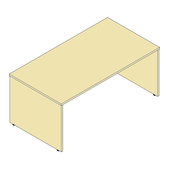
- Page 1 25.03.2019 SLBT1290 / SLBT1790 SLAB 25 DINING TABLE...
- Page 2 1,2,3...
-
Page 3: Table Of Contents
Please check that you have all the panels! RM-WM25-TOP415 (Without 80mm Hole) RM-WM25-TOP417 (Without 80mm Hole) RM-WM25-TOP416 (With 80mm Hole) RM-WM25-TOP418 (With 80mm Hole) RM-WM25-BAC128 RM-WM25-BAC129 RM-WM25-BAC128 RM-WM25-BAC129 1200mm TABLE 1700mm TABLE RM-WM25-LGP071 RM-WM25-LGP071 Please check that you have all the hardware! QUANTITY - 10 QUANTITY - 8 QUANTITY - 8... -
Page 4: Quantity
Diagram A 35mm Maxifix Cam Step 1 Ensure the arrow on Insert the maxifix cams into the this fitting is aligned pre drilled holes on the support with the hole that is brace. The cam should be drilled on the edge of inserted as per diagram A. -
Page 5: Quantity
Step 3 Knock in the gesipa inserts into the holes on the bottom edge of the leg. Repeat for both legs. QUANTITY - 4 M8 Gesipa Insert RM-NUT04 Step 4 Screw the adjustable feet into the bottom of the leg panel. Repeat for both legs. -
Page 6: Quantity
Furniture Connector Pin Diagram C Step 5 Ensure this pin is correctly inserted Screw in the connector pins into the panel. The flat rim of this pin should sit against the edge of the into the pre drilled holes on panel. - Page 7 Step 7 Slide the braces onto the leg panel ensuring that the cam fittings engage over the maxifix pins. Once in place tighten the cams using the 6mm allen key that has been provided to lock the braces into place. Step 8 Slide the remaining leg onto the part assembled frame ensuring that the maxifix pins engage into the maxifix...
- Page 8 Step 9 Place your table top face down onto a clean dry surface and place the assembled frame onto the top ensuring all fittings in the frame engage into the furniture connectors that are pre inserted in the table top. Step 10 Once in position fully tighten all furniture connectors, use a pozi drive screwdriver turning the cams in a clockwise direction.
- Page 9 25.03.2019 SLBB1100 / SLBB1500 SLAB 25 DINING BENCH...
- Page 10 1,2,3...
- Page 11 Please check that you have all the panels! RM-WM25-TOP419 RM-WM25-TOP420 RM-WM25-BAC130 RM-WM25-BAC131 RM-WM25-BAC130 RM-WM25-BAC131 1050mm BENCH 1550mm BENCH RM-WM25-LGP072 RM-WM25-LGP072 Please check that you have all the hardware! QUANTITY - 8 QUANTITY - 8 QUANTITY - 8 Furniture Connector Pin 55mm Maxifix Pin 35mm Maxifix Cam RM-PIN01...
-
Page 12: Quantity
Diagram A 35mm Maxifix Cam Step 1 Ensure the arrow on Insert the maxifix cams into the this fitting is aligned pre drilled holes on the support with the hole that is brace. The cam should be drilled on the edge of inserted as per diagram A. -
Page 13: Quantity
Step 3 Knock in the gesipa inserts into the holes on the bottom edge of the leg. Repeat for both legs. QUANTITY - 4 M8 Gesipa Insert RM-NUT04 Step 4 Screw the adjustable feet into the bottom of the leg panel. Repeat for both legs. -
Page 14: Quantity
Furniture Connector Pin Diagram C Step 5 Ensure this pin is correctly inserted Screw in the connector pins into the panel. The flat rim of this pin should sit against the edge of the into the pre drilled holes on panel. - Page 15 Step 7 Slide the braces onto the leg panel ensuring that the cam fittings engage over the maxifix pins. Once in place tighten the cams using the 6mm allen key that has been provided to lock the braces into place. Step 8 Slide the remaining leg onto the part assembled frame ensuring that the maxifix pins engage into the maxifix...
- Page 16 Step 9 Place the bench top face down onto a clean dry surface and place the assembled frame onto the top ensuring all fittings in the frame engage into the furniture connectors that are pre inserted in the top. Step 10 Once in position fully tighten all furniture connectors, use a pozi drive screwdriver turning the cams in a clockwise direction.


Need help?
Do you have a question about the SLAB 25 SLBT1290 and is the answer not in the manual?
Questions and answers