Advertisement
Quick Links
Advertisement

Related Manuals for dams R1090TC


Summary of Contents for dams R1090TC
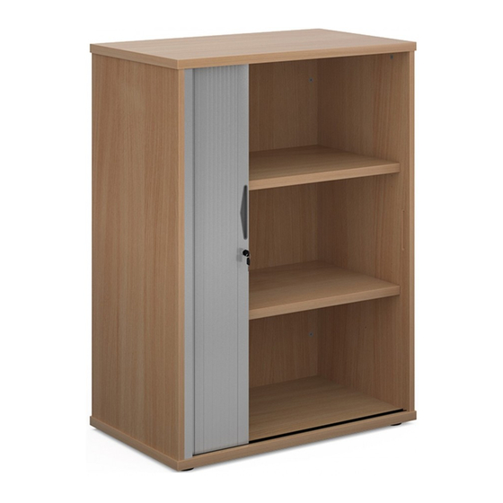
- Page 1 R1090TC 03.02.2020 1090mm Economy Single Door Tambour Cupboard Secondary Storage...
- Page 2 1,2,3...
- Page 3 Please check that you have all the Components! Pack Contents RM-SID232 1 x LH SIDE PANEL - ( RM-SID231) 1 x RH SIDE PANEL - ( RM-SID232 ) 1 x PARTITION PANEL - ( RM-PRT017 ) RM-SID231 1 x FEET KIT - ( RM-FIT251 ) 1 x HARDWARE KIT - ( RM-FIT253 )
- Page 4 Please check that you have all the fittings! Adjustable Foot Outer Adjustable Foot Inner 3.5 x 12mm Wood Screw Fitting Bag RM-SCR73 RM-FIT251 15mm Minifix Cam 24mm Quick fix pin 30mm Wood Dowel 3.5 x 12mm Screw RM-CAM03 RM-BLT006 RM-WOW01 RM-SCR73 Fitting Bag Titus Bung...
- Page 5 RM-SCR73 Step 5 Use the 3.5 x 12mm Screws to secure the top tambour cartridge into place. Qty 3 RM-SCR73 Step 6 Use the 3.5 x 12mm Screws to secure the base tambour cartridge into place. Qty 3 RM-WOW01 RM-BLT006 Step 7 Insert quick fix pins and wood dowels into the pre drilled holes on the top as shown below.
- Page 6 RM-CAM03 RM-WOW01 RM-BLT006 Step 9 Insert Cams, quick fix pins and wood dowels into the pre drilled holes on the LH side panel. Qty 2 Qty 4 Qty 5 See diagram A for details on inserting the cam fittings. EDGE EDGE Diagram A Insert the cam into the 'surface' hole with the arrow aimed at the...
- Page 7 RM-CAM03 RM-WOW01 RM-BLT006 Step 12 Insert Cams, quick fix pins and wood dowels into the pre drilled holes. Qty 6 Qty 2 Qty 2 See diagram A for details on inserting the cam fittings. EDGE EDGE Diagram A Insert the cam into the 'surface' hole with the arrow aimed at the adjacent edge which has the smaller hole.
- Page 8 Step 14 Attach the partition to the back panel and tighten all cam fittings. Step 15 Attach the RH side panel to the part built carcass and tighten all cam fittings.
- Page 9 Step 16 Attach the top ensuring that all pins and dowels correctly locate into the fixing points. Note: Cams shown at point A are covered by the partition panel but can be tightened using the 4mm allen key that has been provided. Step 17 Step 18 Turn the unit onto its head ready to insert...
- Page 10 Step 19 Step 20 Place the base panel onto the carcass ensuring Connect the base to the carcass using the that the door locates into the track and the wood 70mm confirmat screw. RM-CFM02 dowels correctly fit into the pre drilled holes. Qty 8 ADJUSTABLE ADJUSTABLE...
- Page 11 Step 22 Attach the plastic finishing trim to the LH side panel. Remove the backing from the adhesive strip and ensure that the strip is aligned with top and bottom of the LH side panel. See diagrams A & B Attach the door strike plate to the RH side panel using the 3.5x12mm wood screws, ensure you are...
- Page 12 RM-PIN007 Step 24 Screw in the shelf fixing pins, ensure the fixings points are inserted at the Qty 8 same height on both partition and side panel. Note: there is a selection of fixing points that can be used to create different sized openings.
- Page 13 R2140TC 03.02.2020 2140mm Economy Single Door Tambour Cupboard Secondary Storage...
- Page 14 1,2,3...
- Page 15 Please check that you have all the Components! Pack Contents RM-SID230 1 x LH SIDE PANEL - ( RM-SID229) 1 x RH SIDE PANEL - ( RM-SID230 ) 1 x PARTITION PANEL - ( RM-PRT016 ) RM-SID229 1 x FEET KIT - ( RM-FIT251 ) 1 x HARDWARE KIT - ( RM-FIT252 )
- Page 16 Please check that you have all the fittings! Adjustable Foot Outer Adjustable Foot Inner 3.5 x 12mm Wood Screw Fitting Bag RM-SCR73 RM-FIT251 15mm Minifix Cam 24mm Quick fix pin 30mm Wood Dowel 3.5 x 12mm Screw RM-CAM03 RM-BLT006 RM-WOW01 RM-SCR73 Fitting Bag Titus Bung...
- Page 17 RM-SCR73 Step 5 Use the 3.5 x 12mm Screws to secure the top tambour cartridge into place. Qty 3 RM-SCR73 Step 6 Use the 3.5 x 12mm Screws to secure the base tambour cartridge into place. Qty 3 RM-WOW01 RM-BLT006 Step 7 Insert quick fix pins and wood dowels into the pre drilled holes on the top as shown below.
- Page 18 RM-CAM03 RM-WOW01 RM-BLT006 Step 9 Insert Cams, quick fix pins and wood dowels into the pre drilled holes on the LH side panel. Qty 2 Qty 4 Qty 5 See diagram A for details on inserting the cam fittings. EDGE EDGE Diagram A Insert the cam into the 'surface' hole with the arrow aimed at the...
- Page 19 RM-CAM03 RM-WOW01 RM-BLT006 Step 12 Insert Cams, quick fix pins and wood dowels into the pre drilled holes. See diagram A for details on inserting the cam fittings. Qty 12 Qty 4 Qty 5 EDGE EDGE Diagram A Insert the cam into the 'surface' hole with the arrow aimed at the adjacent edge which has the smaller hole.
- Page 20 Step 14 Attach the partition to the back panel and tighten all cam fittings. Step 15 Attach the RH side panel to the part built carcass and tighten all cam fittings.
- Page 21 Step 16 Attach the top ensuring that all pins and dowels correctly locate into the fixing points. Cams shown at point A are covered by the partition panel but can be tightened using the 4mm allen key that has been provided. Step 17 Step 18 Turn the unit onto its head ready to insert the...
- Page 22 Step 19 Step 20 Place the base panel onto the carcass ensuring Connect the base to the carcass using the 70mm that the door locates into the track and the wood confirmat screw. RM-CFM02 dowels correctly fit into the pre drilled holes. Qty 8 ADJUSTABLE ADJUSTABLE...
- Page 23 Step 22 Attach the plastic finishing trim to the LH side panel. Remove the backing from the adhesive strip and ensure that the strip is aligned with top and bottom Diagram A of the LH side panel. See diagrams A & B Attach the door strike plate to the RH side panel using the 3.5x12mm wood screws,...
- Page 24 Step 24 Step 25 Screw in the shelf fixing Insert the shelves into the cupboard, ensure that the pins, ensure the fixings points are inserted at the shelf support bungs fully same height on both engage into the shelf pin, they may need to be lightly partition and side panel.
Need help?
Do you have a question about the R1090TC and is the answer not in the manual?
Questions and answers