
Subscribe to Our Youtube Channel
Related Manuals for dams Flux FL-IS1


Summary of Contents for dams Flux FL-IS1
- Page 1 16-12-2021 Flux - Shelf Panels FL-IS1 - FL-IS2 - FL-TS1 - FL-TS2 Pack 1: ASSEMBLY 1x Shelf Panel INSTRUCTIONS Flux Shelf Panels...
- Page 2 **mm **mm 1,2,3...
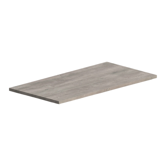
- Page 3 Please check that you have all the panels PACK 1: 378 x 378mm = FL-IS1 1 x Shelf 778 x 378mm = FL-IS2 420 x 420mm = FL-TS1 820 x 420mm = FL-TS2 FL-IS1 FL-IS2 FL-TS1 FL-TS2 Please check that you have all the fittings FITTINGS SUPPLIED Knock-in Insert Size...
- Page 4 FLUX SHELF ASSEMBLY Step 1 Unpack your new Flux shelf panel and please recycle all packaging. Step 2 Insert the 4x nylon knock-in inserts into the holes located on the underside of the base. Step 3 Screw the 4x M4 steel pins into the nylon inserts.
- Page 5 Step 4 Position the shelf into the frame as shown...
- Page 6 16-12-2021 Flux - Cubby Units FL-CB1 - FL-CB2 - FL-CS1 Pack 1: ASSEMBLY 1x Top, Base & Side Panels INSTRUCTIONS Flux Cubby Units...
- Page 7 **mm **mm 1,2,3...
- Page 8 Please check that you have all the panels PACK 1: 378 x 378mm = FL-CB1 1 x Cubby 778 x 378mm = FL-CB2 378 x 189mm = FL-CS1 FL-CB1 FL-CB2 FL-CS1 Please check that you have all the fittings FITTINGS SUPPLIED Confirmate Screw Knock-in Insert Size...
- Page 9 FLUX CUBBY ASSEMBLY Step 1 Unpack your new cubby unit and please recycle all packaging. Step 2 Insert the 6x dowels into the side panels, and tap gently in with a hammer / mallet. Step 3 Insert the 4x nylon knock-in inserts into the holes located on the underside of the base.
- Page 10 Step 4 Position the sides underneath the base panel Locate and tighten the 6x confirmat screws clockwise Step 5 Turn-over the cubby and place the top panel and tap in place. Step 3 Locate the cubby into the frame and from the underside screw in the 4x M4 steel pins.
- Page 11 17-12-2021 Flux - Planter Units FL-PL1 - FL-PL2 Pack 1: ASSEMBLY 1x Base & Side Panels INSTRUCTIONS Flux Planter Units...
- Page 12 **mm **mm 1,2,3...
- Page 13 Please check that you have all the panels PACK 1: 378 x 378mm = FL-PL1 1 x Planter 778 x 378mm = FL-PL2 FL-PL1 FL-PL2 Please check that you have all the fittings FITTINGS SUPPLIED Confirmat Screw Knock-in Insert Size Size 50mm 13mm...
- Page 14 FLUX PLANTER ASSEMBLY Step 1 Unpack your new Flux planter unit and please recycle all packaging. Step 2 Insert the 8x dowels into the side panels, and tap gently in with a hammer / mallet. Step 3 Insert the 8x knock-in pins into the holes located on the side panels as shown.
- Page 15 Step 4 Align the pins in the sides to the facia panels and slot in place (ensure the cam arrow is facing the panel edge) Once both panels are positioned, turn the minifix cam clockwise to tighten to secure. Step 5 Insert the 4x knock-in inserts into the holes located on the base panel as shown.
- Page 16 Step 4 Screw the 4x M4 steel pins into the inserts as shown. Step 5 Turn-over the planer and place on on top of the desired frame.
Need help?
Do you have a question about the Flux FL-IS1 and is the answer not in the manual?
Questions and answers