Table of Contents
Advertisement
Quick Links
Operation
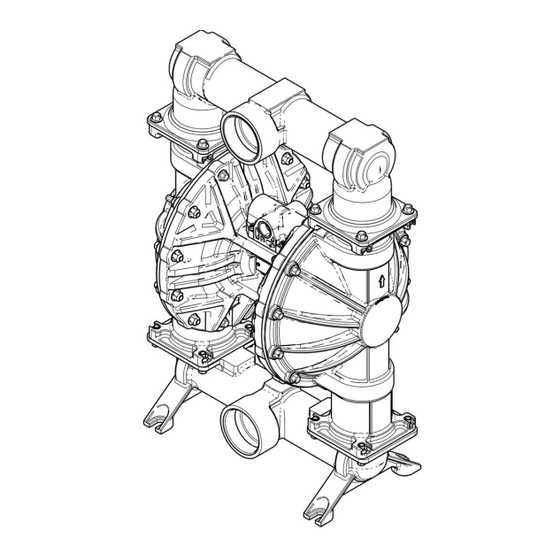
Husky™ 3250 Air-Operated
Diaphragm Pump
SST and aluminum pumps for fluid transfer applications, including high viscosity
materials. For professional use only.
Not approved for use in European explosive atmosphere locations.
125 psi (0.86 MPa, 8.6 bar) Maximum Fluid Working Pressure
125 psi (0.86 MPa, 8.6 bar) Maximum Air Working Pressure
Important Safety Instructions
Read all warnings and instructions in this
manual before using the equipment. Be
familiar with the proper control and usage
of the equipment. Save these instructions.
3A7661B
EN
Advertisement
Table of Contents

Related Manuals for Graco Husky 3250


Summary of Contents for Graco Husky 3250
- Page 1 Operation Husky™ 3250 Air-Operated Diaphragm Pump 3A7661B SST and aluminum pumps for fluid transfer applications, including high viscosity materials. For professional use only. Not approved for use in European explosive atmosphere locations. 125 psi (0.86 MPa, 8.6 bar) Maximum Fluid Working Pressure 125 psi (0.86 MPa, 8.6 bar) Maximum Air Working Pressure Important Safety Instructions Read all warnings and instructions in this...
-
Page 2: Table Of Contents
Fluid Supply Line ......... 15 Performance Charts..........23 Fluid Outlet Line........... 15 Technical Specifications........25 Fluid Pressure Relief Valve......15 Notes..............27 Operation ............17 Pressure Relief Procedure......17 Graco Standard Husky Pump Warranty....28 Related Manuals Manuals Related Related Manuals Manual Manual... -
Page 3: Safety Symbols
Safety Symbols Safety Symbols Symbols Safety Safety Symbols The following safety symbols appear throughout this manual and on warning labels. Read the table below to understand what each symbol means. Symbol Symbol Symbol Meaning Meaning Meaning Symbol Symbol Symbol Meaning Meaning Meaning Burn Hazard... -
Page 4: Warnings
Warnings Warnings Warnings Warnings The following warnings apply throughout this manual. Read, understand, and follow the warnings before using this equipment. Failure to follow these warnings can result in serious injury. WARNING WARNING WARNING FIRE FIRE FIRE AND AND EXPLOSION EXPLOSION HAZARD EXPLOSION HAZARD... - Page 5 Warnings WARNING WARNING WARNING EQUIPMENT MISUSE MISUSE HAZARD HAZARD EQUIPMENT EQUIPMENT MISUSE HAZARD Misuse can cause death or serious injury. • Do not operate the unit when fatigued or under the influence of drugs or alcohol. • Do not exceed the maximum working pressure or temperature rating of the lowest rated Technical Specifications Specifications in all equipment manuals.
- Page 6 Warnings WARNING WARNING WARNING PLASTIC PARTS PARTS CLEANING CLEANING SOLVENT SOLVENT HAZARD HAZARD PLASTIC PLASTIC PARTS CLEANING SOLVENT HAZARD Many cleaning solvents can degrade plastic parts and cause them to fail, which could cause serious injury or property damage. • Use only compatible solvents to clean plastic structural or pressure-containing parts. Technical Specifications Specifications in all equipment manuals for materials of construction.
-
Page 7: Configuration Number Matrix
Configuration Number Matrix Configuration Number Number Matrix Matrix Configuration Configuration Number Matrix For the Configuration Number of your pump, see the identification plate (ID) on top of the center section. Use the following tables to determine the pump components. 3250S–PP01AS1PPPTPSPT 3250S–PP01AS1PPPTPSPT 3250S–PP01AS1PPPTPSPT Sample... - Page 8 Configuration Number Matrix Seat Seat Seat Material Material Material Ball Ball Ball Material Material Material Diaphragm Diaphragm Material Diaphragm Material Material Manifold Manifold and Manifold and Seat Seat Seat Seal Material Material Seal Seal Material Polypropylene ■ PTFE ■ ■ Santoprene PTFE PTFE/EPDM Overmolded ■...
-
Page 9: Installation
NOTICE NOTICE selecting and installing system components. Contact your Graco distributor for assistance in planning a Cavitation in an AODD pump is the formation and system to suit your needs. Always use Genuine collapse of bubbles in the pumped liquid. Frequent Graco Parts and accessories. -
Page 10: Mount The Pump
See Dimensions, page 22, for dimensions of the Graco recommends taking all the above factors mounting holes for your equipment. into account in system design. To maintain pump efficiency, supply only enough air pressure to the... - Page 11 Installation Figure 1 Typical Installation Accessories/Components Not Not Supplied Supplied System Components Components Accessories/Components Accessories/Components Supplied System System Components Air supply line Air inlet port (not visible) Bleed-type master air valve (may be Air exhaust port and muffler required for your pump) Air filter/regulator assembly Fluid inlet port Master air valve (to isolate the...
-
Page 12: Ground The System
Installation Ground The The System System Air Lines Lines Ground Ground System Lines 1. Install an air filter/regulator assembly (C). The regulator controls the fluid pressure. The fluid stall pressure will be the same as the setting of the air regulator. The filter removes harmful dirt The equipment must be grounded to reduce the and moisture from the compressed air supply. -
Page 13: Air Exhaust Ventilation
Installation Air Exhaust Exhaust Ventilation Ventilation Exhaust Ventilation To provide provide provide a a a remote remote exhaust: remote exhaust: exhaust: 1. Remove the muffler (U) from the pump air exhaust port (K). Be sure the system is properly ventilated for your 2. - Page 14 Installation Figure 2 Typical Air Exhaust Ventilation Air supply line Air exhaust port Bleed-type master air valve (may be Conductive air exhaust hose required for your pump installation) Air filter/regulator assembly Conductive container for remote air exhaust Master air valve (for accessories) Muffler Air inlet port (not visible) 3A7661B...
-
Page 15: Fluid Supply Line
Installation Fluid Supply Supply Line Line Fluid Outlet Outlet Line Line Fluid Fluid Supply Line Fluid Fluid Outlet Line 1. Use conductive, flexible fluid hoses. See Ground The System, page 2. Install a fluid drain valve (F) near the fluid outlet. 3. - Page 16 Installation KEY: KEY: KEY: Fluid inlet port Fluid outlet port Fluid pressure relief valve Install valve between fluid inlet and outlet ports. Connect fluid inlet line here. Connect fluid outlet line here. Figure 3 Fluid Pressure Relief Valve 3A7661B...
-
Page 17: Operation
Operation Operation Operation Operation Pressure Pressure Pressure Relief Relief Procedure Relief Procedure Procedure Flush Flush the Flush the Equipment Equipment Equipment Follow the Pressure Relief Procedure Flush the equipment before each use. Determine whenever you see this symbol. whether to disassemble and clean individual parts or simply flush the equipment with a compatible solvent or sanitizing solution. -
Page 18: Shut Down The Equipment
Operation 8. To prime the pump, slowly increase air 9. If you are flushing, run the pump long enough to pressure with the air regulator (C) until thoroughly clean the pump and hoses. pump starts to cycle. Do not exceed the 10. -
Page 19: Maintenance
Maintenance Maintenance Maintenance Maintenance NOTICE NOTICE NOTICE Establish a a a Preventive Preventive Maintenance Maintenance Establish Establish Preventive Maintenance Schedule Schedule Schedule Firmly tighten all connections to avoid leaks and damage to equipment parts. NOTICE NOTICE NOTICE Regularly maintain the equipment to avoid pump Lubricate the the Equipment Equipment... -
Page 20: Flush The Equipment
Maintenance Flush the the Equipment Equipment Store the the Equipment Equipment Flush Flush Equipment Store Store Equipment Always relieve the pressure and flush the equipment before storing the equipment for any length of time. To avoid fire and explosion, always ground 1. -
Page 21: Torque Instructions
Torque Instructions Torque Instructions Instructions Torque Torque Instructions If fluid cover or manifold fasteners have been Inlet Inlet Inlet and and Outlet Outlet Outlet Manifold Manifold Manifold fasteners fasteners fasteners loosened, it is important to torque them using the following procedure to improve sealing. NOTE: Fluid cover and manifold fasteners have a NOTE: NOTE:... -
Page 22: Dimensions
Dimensions Dimensions Dimensions Dimensions Center Port Port Models, Models, Stainless Stainless Steel Steel Center Center Port Models, Stainless Steel and Aluminum Aluminum Aluminum Stainless Steel Steel Aluminum Aluminum Aluminum Stainless Steel Steel Aluminum Aluminum Aluminum Stainless Stainless Steel Stainless Stainless Steel A A A G G G... -
Page 23: Performance Charts
Performance Charts Performance Charts Charts Performance Performance Charts Bolt Bolt Bolt - - - through through Diaphragms through Diaphragms Diaphragms Fluid Pressure Pressure Fluid Fluid Pressure Approximate Approximate Approximate Cycles Cycles Cycles per per Minute Minute Minute Operating Operating Operating Air Air Pressure Pressure Pressure... -
Page 24: Overmolded Diaphragms
Performance Charts Overmolded Diaphragms Diaphragms Overmolded Overmolded Diaphragms Fluid Fluid Fluid Pressure Pressure Pressure Approximate Cycles Cycles per per Minute Minute Approximate Approximate Cycles Minute Operating Operating Operating Air Air Pressure Pressure Pressure (MPa, bar) bar) (MPa, (MPa, bar) A A A 125 psi (0.86 MPa, 8.6 bar) B B B 100 psi (0.7 MPa, 7.0 bar) -
Page 25: Technical Specifications
Technical Specifications Technical Specifications Specifications Technical Technical Specifications Husky Husky Husky 3250 3250 Diaphragm 3250 Diaphragm Diaphragm Pump Pump Pump Metric Metric Metric Maximum fluid working pressure 125 psi 0.86 MPa, 8.6 bar Air pressure operating range 20 to 125 psi 0.14 to 0.86 MPa, 1.4 to 8.6 bar... - Page 26 California Proposition 65 Maximum Maximum Maximum pump pump pump speed speed speed 112 cycles per minute Standard diaphragms Overmolded diaphragms 128 cycles per minute Weight Weight Weight Stainless steel 190.0 lb 86.2 kg Aluminum 95.0 lb 43.1 kg Wetted Wetted Wetted Parts Parts Parts...
-
Page 27: Notes
Notes Notes Notes Notes 3A7661B... -
Page 28: Graco Standard Husky Pump Warranty
Graco to be defective. This warranty applies only when the equipment is installed, operated and maintained in accordance with Graco’s written recommendations. This warranty does not cover, and Graco shall not be liable for general wear and tear, or any malfunction, damage or wear caused by faulty installation, misapplication, abrasion, corrosion, inadequate or improper maintenance, negligence, accident, tampering, or substitution of non-Graco component parts.
Need help?
Do you have a question about the Husky 3250 and is the answer not in the manual?
Questions and answers