Graco Husky 1040 Instructions-Parts List Manual
Air-operated diaphragm pumps
Hide thumbs
Also See for Husky 1040:
- Instructions-parts list manual (34 pages) ,
- Instructions-parts list (4 pages) ,
- Instructions-parts list manual (34 pages)
Table of Contents
Advertisement
Instructions - Parts List
ACETAL, POLYPROPYLENE, AND PVDF
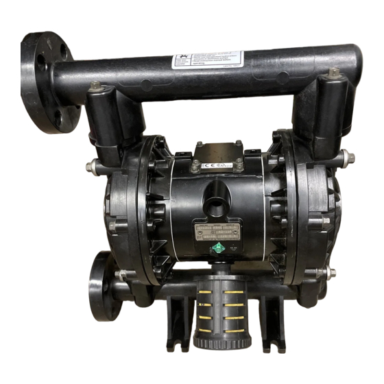
Husky™ 1040 Air-Operated
Diaphragm Pumps
1–inch AODD pump for fluid transfer applications. For professional use only.
Not approved to European explosive atmosphere requirements.
See Models on page 2 for a list of pump models and descriptions.
120 psi (0.8 MPa, 8 bar) Maximum Fluid Working Pressure
120 psi (0.8 MPa, 8 bar) Maximum Air Input Pressure
Important Safety Instructions
Read all warnings and instructions in the manual.
Save these instructions.
308443ZAE
EN
Advertisement
Table of Contents

Related Manuals for Graco Husky 1040


Summary of Contents for Graco Husky 1040
- Page 1 Instructions - Parts List ACETAL, POLYPROPYLENE, AND PVDF Husky™ 1040 Air-Operated 308443ZAE Diaphragm Pumps 1–inch AODD pump for fluid transfer applications. For professional use only. Not approved to European explosive atmosphere requirements. See Models on page 2 for a list of pump models and descriptions. 120 psi (0.8 MPa, 8 bar) Maximum Fluid Working Pressure 120 psi (0.8 MPa, 8 bar) Maximum Air Input Pressure Important Safety Instructions...
-
Page 2: Table Of Contents
Ball Check Valve Repair ....18 Graco Information ......36 Diaphragm Repair . -
Page 3: Warnings
Read all instruction manuals, tags, and labels before operating the equipment. • Use the equipment only for its intended purpose. If you are not sure, call your Graco distributor. • Do not alter or modify this equipment. Use only genuine Graco parts and accessories. - Page 4 WARNING TOXIC FLUID HAZARD Hazardous fluid or toxic fumes can cause serious injury or death if splashed in the eyes or on the skin, inhaled, or swallowed. • Know the specific hazards of the fluid you are using. • Store hazardous fluid in an approved container. Dispose of hazardous fluid according to all local, state and national guidelines.
-
Page 5: Installation
• Always use Genuine Graco Parts and Accessories. • Reference numbers and letters in parentheses refer to the callouts in the figures and the parts lists on pages 29–31. - Page 6 The acetal pump contains stainless steel fibers which fluid containers during filling. This is only a guide; make the wetted parts conductive. Attaching the contact your Graco distributor for assistance in ground wire to the grounding screw will ground the air grounding your system.
- Page 7 Installation Air Line b. Locate one bleed-type master air valve (B) close to the pump and use it to relieve trapped air. See the WARNING at left. Locate the other WARNING master air valve (E) upstream from all air line accessories and use it to isolate them during cleaning and repair.
- Page 8 3. Install a shutoff valve (K) in the fluid outlet line. 3. Connect remaining end of tubes to external air signal, such as Graco’s Cycleflo (P/N 195264) or Cycleflo II (P/N 195265) controllers. NOTE: the air pressure at the connectors must be at least 30% of the air pressure to the motor for the pump to operate.
- Page 9 Installation Flange Connections 1. Place a lockwasher and a flat washer on each bolt. Refer to Fig. 3. The fluid inlet and outlet ports are 1” raised face flanges. Connect 1” flanged plastic pipe to the pump as follows. 2. Align the holes in the gasket and the pipe flange You will need: with the holes in the pump flange.
- Page 10 Installation Changing the Orientation of the Fluid Inlet Fluid Pressure Relief Valve and Outlet Ports CAUTION The pump is shipped with the fluid inlet (R) and outlet (S) ports facing the same direction. See Fig. 4. To change the orientation of the inlet and/or outlet port: Some systems may require installation of a pressure relief valve at the pump outlet to prevent 1.
- Page 11 Installation Air Exhaust Ventilation The air exhaust port is 3/4 npt(f). Do not restrict the air exhaust port. Excessive exhaust restriction can cause WARNING erratic pump operation. To provide a remote exhaust: FIRE AND EXPLOSION HAZARD 1. Remove the muffler (P) from the pump air exhaust port.
-
Page 12: Operation
Operation Pressure Relief Procedure 1. Be sure the pump is properly grounded. Refer to Grounding on page 6. WARNING 2. Check all fittings to be sure they are tight. Be sure to use a compatible liquid thread sealant on all male threads. -
Page 13: Maintenance
Operation Operation of Remote Piloted Pumps NOTE: Leaving air pressure applied to the air motor for extended periods when the pump is not running may 1. Follow preceding steps 1 through 7 of Starting and shorten the diaphragm life. Using a 3-way solenoid Adjusting the Pump. -
Page 14: Troubleshooting
Troubleshooting • Relieve the pressure before checking or servicing WARNING the equipment. • Check all possible problems and causes before disassembling the pump. To reduce the risk of serious injury whenever you are instructed to relieve pressure, always follow the Pressure Relief Procedure on page 12. - Page 15 Troubleshooting PROBLEM CAUSE SOLUTION Fluid in exhaust air. Diaphragm ruptured. Replace. See pages 19 to 21. Loose fluid side plate (105). Tighten or replace (pages 19 to 21). Pump exhausts excessive Worn air valve block (7), o-ring (6), Repair or replace. See pages 16 to 17. air at stall.
-
Page 16: Service
Service Repairing the Air Valve 7. Clean all parts and inspect for wear or damage. Replace as needed. Reassemble as explained on Tools Required page 17. • Torque wrench Torque to 50–60 in-lb • Torx (T20) screwdriver or 7 mm (9/32”) socket (5.6–6.8 N-m). - Page 17 Service Reassembly Insert narrow end first. 1. If you removed the bearings (12, 15), reinstall as Grease. explained on page 23. Reassemble the fluid Install with lips facing narrow end of piston (11). section. Insert wide end first. 2. On aluminum center housing models, install the valve plate seal (9) into the groove at the bottom of the valve cavity.
-
Page 18: Ball Check Valve Repair
Service Ball Check Valve Repair Reassembly 1. Clean all parts and inspect for wear or damage. Tools Required Replace parts as needed. • Torque wrench 2. Reassemble in the reverse order, following all notes • 10 mm socket wrench in Fig. 11. Be sure the ball checks exactly as shown. -
Page 19: Diaphragm Repair
Service Diaphragm Repair WARNING Tools Required • Torque wrench To reduce the risk of serious injury whenever you are instructed to relieve pressure, always follow the • 10 mm socket wrench Pressure Relief Procedure on page 12. • 19 mm open–end wrench •... - Page 20 Service 4. Unscrew one outer plate (105) from the diaphragm Reassembly – Standard Diaphragms shaft (24). Remove one diaphragm (401), and the 1. Grease the shaft u-cup packings (402*) and install inner plate (104). See Fig. 13. them so the lips face out of the housing (1). See Fig.
- Page 21 Reassembly – Overmolded Diaphragms 5. Assemble the other diaphragm assembly to the shaft as explained in step 2. This diaphragm will be lifted off the air cover at this point. WARNING 6. Supply the pump with low pressure air (less than 7 psi [0.05 MPa, 0.5 bar]).
- Page 22 Service 402* 403* 401* Cutaway View, with Diaphragms Removed Cutaway View, with Diaphragms in Place 401* 403* Lips face out of housing (1). Rounded side faces diaphragm (401). Air Side must face center housing (1). Grease. Apply medium-strength (blue) Loctite® or equivalent. Torque to 20 to 25 ft-lb (27to 34 N-m) at 100 rpm maximum.
-
Page 23: Bearing And Air Gasket Removal
Service Bearing and Air Gasket Removal Reassembly 1. If removed, install the shaft u-cup packings (402*) Tools Required so the lips face out of the housing (1). • Torque wrench 2. The bearings (19, 12, and 15) are tapered and can •... - Page 24 Service Insert bearings tapered end first. Press-fit bearings flush with surface of center housing (1). Apply medium-strength (blue) Loctite® or equivalent. Torque to 130 to 150 in-lb (14 to 17 N•m). 04158 Detail of Air Valve Bearings Fig. 14 24 308443...
- Page 25 Notes 308443 25...
-
Page 26: Pump Matrix
Pump Matrix Husky 1040 Acetal, Polypropylene, and PVDF Pumps, Series A Your Model No. is marked on the pump’s serial plate. To determine the Model No. of your pump from the following matrix, select the six digits which describe your pump, working from left to right. The first digit is always D, designating Husky diaphragm pumps. -
Page 27: Repair Kit Matrix
G (Geolast Part No. 253626: Husky 1040 HD Overmolded PTFE/EPDM Diaphragm Repair Kit. Part No. 289224: Husky 1040 HD Overmolded PTFE/EPDM Diaphragm Repair Kit, with new air side diaphragm plates. Part No. 4F396: Husky 1040 PTFE/Santoprene Backer Diaphragm Repair Kit. -
Page 28: Parts
Parts † † † † † † † † ▲ † ‡ • 401* 402* 403* 301* 201* 202* ‡ Not used on some models. These parts are included in the Pump Repair Kit, which may be purchased separately. - Page 29 Parts Air Motor Parts List (Matrix Column 2) Air Motor Parts List (Matrix Column 2) Ref. Ref. Digit Part No. Description Digit Part No. Description 188838 HOUSING, center; Same as 7 with the following exceptions aluminum 195921 HOUSING, center; 188854 COVER, air valve;...
- Page 30 Fluid Section Parts List (Matrix Column 3) Fluid Section Parts List (Matrix Column 3) Ref. Ref. Digit Part No. Description Qty. Digit Part No. Description Qty. 189377 COVER, fluid; acetal 189378 COVER, fluid; PVDF 189371 MANIFOLD, inlet; acetal 189372 MANIFOLD, inlet; PVDF 189374 MANIFOLD, outlet;...
- Page 31 Seat Parts List (Matrix Column 4) Diaphragm Parts List (Matrix Column 6) Ref. Ref. Digit Part No. Description Digit Part No. Description 401* DIAPHRAGM, backup; Not sold 201* 188604 SEAT; acetal separately polychloroprene (CR) 202* 109205 O-RING; PTFE 402* 112181 PACKING, u-cup;...
-
Page 32: Torque Sequence
Torque Sequence Always follow torque sequence when instructed to torque fasteners. 1. Left/Right Fluid Cover 3. Outlet Manifold Torque Bolts to 130–150 in–lb (14–17 N•m) Torque Bolts to 80–90 in–lb (9–10 N•m) TOP VIEW SIDE VIEW 2. Inlet Manifold Torque Bolts to 80–90 in–lb (9–10 N•m) BOTTOM VIEW 32 308443... -
Page 33: Dimensional Drawings
Dimensional Drawings FRONT VIEW ANSI Flange Fluid Outlet SIDE VIEW PUMP MOUNTING HOLE PATTERN 45° 308443 33... -
Page 34: Technical Data
Technical Data Maximum fluid working pressure....120 psi Wetted parts ..Vary by Model. See pages 29 and 31. (0.8 MPa, 8 bar) Non-wetted external partsaluminum, 302, 316 stainless steel, Air pressure operating range. -
Page 35: Performance Chart
Performance Chart Technical Data and Performance Chart Test Conditions: The pump had PTFE 2-piece diaphragms and was tested in water with inlet submerged. Fluid Pressure Curves A at 120 psi (0.83 MPa, 8.3 bar) air pressure B at 100 psi (0.7 MPa, 7 bar) air (0.86, 8.6) pressure C at 70 psi (0.48 MPa, 4.8 bar) air... -
Page 36: Graco Standard Husky Pump Warranty
With the exception of any special, extended, or limited warranty published by Graco, Graco will, for a period of twelve months from the date of sale, repair or replace any part of the equipment determined by Graco to be defective.
Need help?
Do you have a question about the Husky 1040 and is the answer not in the manual?
Questions and answers