Table of Contents
Advertisement
Quick Links
®
Reference Guide for Microprocessor Controller
Please read and save these instructions for future reference. Read carefully before attempting to assemble, install,
operate or maintain the product described. Protect yourself and others by observing all safety information. Failure
to comply with these instructions will result in voiding of the product warranty and may result in personal injury
and/or property damage.
DOAS v8.1
Version date 1/23
Program Features
The microprocessor controller offers control through
easy monitoring and adjustment of unit parameters by
way of a lighted graphical display and an integral push-
button keypad.
Pre-Programmed Operating Sequences
The controller has been pre-programmed to offer
multiple control sequences to provide tempered air.
Factory default settings allow for easy setup and
commissioning. The sequence parameters are fully
adjustable. Refer to the Sequence of Operation for
details.
BMS Communication
The user can remotely adjust setpoints, view unit status
points and alarms. The microprocessor controller is
capable of communicating over several protocols:
• BACnet® MSTP
• BACnet® IP
Reference Points List for a complete list of BMS points.
Built-In Occupancy Schedule
The controller has an internal programmable time clock,
allowing the user to set occupancy schedules for each
day of the week. The controller option also has morning
warm-up and cool down capability for improved
comfort at the time of occupancy.
Alarm Management
The microprocessor controller will monitor the unit's
status for alarm conditions. Upon detecting an alarm,
the controller will record the alarm description, time,
date, and input/output status points for user review.
Alarms are also communicated via BMS (if equipped).
Introduction
• Modbus RTU
• Modbus TCP
Microprocessor Controller for
Dedicated Outdoor Air System
Technical Support
Call 1-866-478-2574
Occupancy Modes
The microprocessor controller offers three modes of
determining occupancy: a digital input, occupancy
schedule or the BMS. If in the unoccupied mode, the
unit will either be shut down, continue normal operation
utilizing adjustable unoccupied setpoints, recirculate
with unoccupied setpoints or will cycle on to maintain
adjustable unoccupied space temperature and humidity
setpoints (space temperature and humidity sensor is
optional).
Remote Unit Access (if equipped)
The WebUI and Remote Display are two ways to gain
access to the unit controller allowing monitoring of the
unit and parameter adjustment without being at the
unit.
The WebUI can be accessed via a building network
and is included with every unit controller. The Remote
Display is an LCD to be panel mounted in a remote
location and is an option available for purchase.
WARNING
Electrical shock hazard. Can cause personal injury or
equipment damage. Service must be performed only
by personnel that are knowledgeable in the operation
of the equipment being controlled.
WARNING
Mechanical high static protection cutoffs must
be installed by others to protect the system and
equipment from over-pressurization when using
factory provided control sensors. The manufacturer
does not assume responsibility for this.
Microprocessor Controller for DOAS
Document 485936
1
Advertisement
Table of Contents

Related Manuals for Greenheck DOAS v8.1


Summary of Contents for Greenheck DOAS v8.1
- Page 1 Protect yourself and others by observing all safety information. Failure to comply with these instructions will result in voiding of the product warranty and may result in personal injury and/or property damage. DOAS v8.1 Technical Support Call 1-866-478-2574...
-
Page 2: Table Of Contents
Table of Contents Sequence of Operation ....3 Display Use ..... 10 Parameter Adjustment . -
Page 3: Sequence Of Operation
Sequence of Operation The microprocessor controller can be configured for The following occurs during a soft shutdown: air handler, energy recovery, and dedicated outdoor air • Tempering outputs immediately revert back to their systems. Each application utilizes similar technologies off value; while for heating and cooling: chilled water, hot water, indirect •... - Page 4 Sequence of Operation Night Setback: Unoccupied mode when there • Space Temperature Reset: The controller will is space temperature and/or humidity sensor(s) adjust the supply air temperature setpoint between connected to the controller. The unit will cycle the min (55°F) and max (90°F) to satisfy the desired on to maintain unoccupied space setpoints if occupied or unoccupied space temperature setpoints there is a call for unoccupied heating, cooling or...
- Page 5 Sequence of Operation • Hot Water: Microprocessor controller will modulate a Additionally, non-modulating fans are staged using hot water valve (provided by others) to maintain the digital outputs and an offset. Each additional stage supply temperature setpoint. Coil freeze protection turns on based on the saturated temperature must be provided by others in the field! reaching setpoint plus an offset and turns off when...
- Page 6 Sequence of Operation Heating: In heating mode, the pressure reading The outside temperature increases by 5ºF. from the transducer is converted to a saturated The outside humidity decreases by 20%RH, if suction temperature for each circuit. The humidity sensor is installed. temperature, or minimum temperature when two The unit has been locked out for more than 2 circuits are present, is compared to a setpoint.
- Page 7 Sequence of Operation Dehumidification • 0-10 VDC: The supply fan is enabled by the unit controller. An external field-supplied 0-10 VDC signal Dehumidification enable can be selected based on is responsible for modulating the supply fan’s speed. any of the following sensor readings: outside air •...
- Page 8 Sequence of Operation • Space Static Pressure: The exhaust fan modulates Energy Wheel Control to maintain a space static pressure setpoint based on a sensor located in the space. A space static Economizer: If the unit is equipped with an energy pressure sensor or BMS communicated value in recovery wheel, the economizer will modulate/stop the required for this sequence.
- Page 9 Sequence of Operation Frost Control (Aluminum): The microprocessor controller will activate the frost control based on the following methods. • Electric Preheater: When the outdoor air temperature is less than 10°F (adj.), the preheater is energized to defrost the wheel. •...
-
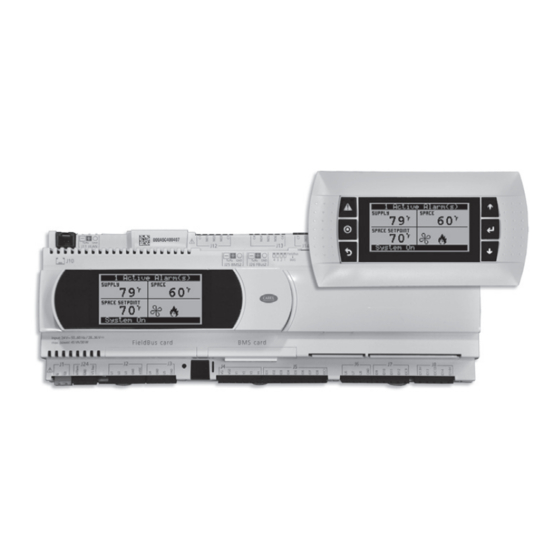
Page 10: Display Use
Display Use The microprocessor controller is located in the unit control center. The face of the controller has six buttons, allowing the user to view unit conditions and alter parameters. The microprocessor controller is pre-programmed with easy to use menus. A remote display is also available. Keypad Description Button Description... -
Page 11: Web User Interface
Web User Interface The Web User Interface allows access to the unit controller through the building network. Reference Ctrl Variables/ Advanced/Network Settings to set the IP network protocol. Once proper communication is established, the user can click on the follow tabs: Overview –... -
Page 12: Main Menu
Main Menu Navigation Unit Enable Main Status Ctrl Variables Alarm Menu Temp Control Unit Status Alarm History Dehumidification Input Output Status Active Alarms Note: Compressor Control Reset History Additional status screens are displayed depending Pressure Control Refrigeration Clear History on unit configuration. Screens may include, but Heat Pump Control Export History... -
Page 13: Unit Status Overview
Unit Status Overview The microprocessor controller will revert to a default main menu loop. This loop includes several screens to view the operating conditions of the unit. Scroll through the menu screens by using the buttons. he iniTial menu screen displays The job name uniT Tag uniT sTaTus ouTside... - Page 14 Unit Status Overview abb F TaTus This screen appears if equipped with a Modbus controlled VFD. This screen displays the fan speed, current, torque, bus voltage, output voltage and power consumption being sent form the VFD to the controller. xhausT TaTus This screen displays the fan enable command, fan proving status, and the exhaust fan ramp being sent from the controller to the VFD.
- Page 15 Unit Status Overview uTpuT The CO Ramp Output screen will be active if the unit is configured for CO control. This screen displays the CO setpoint, CO level from the space, and the status of the control ramp. nergy ecovery TaTus This screen provides overall status of the energy recovery device.
- Page 16 Unit Status Overview TaTus The ExV Status screen is active when the unit is equipped with an inverter scroll compressor and electronic expansion valve (ExV). The screen displays information from the EVD (electronic valve driver) including the number of steps (stp) of the valve, the open percentage of the valve, the EVD control status, the suction superheat, the suction temperature, the suction pressure, and the saturated suction temperature.
- Page 17 Unit Status Overview hgrh r This screen will display the status of the hot gas reheat ramp. The screen includes the active setpoint, supply air discharge temperature, the ramp status, and hot gas reheat valve request being sent from the controller. upply pace TaTic...
-
Page 18: Menu
Menu The controller is equipped with several menus to help guide users with altering program parameters. The following menus can be accessed by pressing the button. To enter the desired menu, press the button. The Unit Enable menu allows the user to enable and disable the unit through the Unit Enable controller. - Page 19 Menu emperaTure eTpoinT One of the setpoint screens appears when supply temp control, space reset, or return reset is selected as the reset control mode. Setpoint Selections: Local – The space setpoint will be constant; set from screen (e.g. 72°F). BMS –...
- Page 20 Menu ooling ockouT This screen displays the cooling lockout temperature. Cooling will be disabled when outside air is below the cooling lockout temperature (55ºF). conomizer ockouT The screen displays the economizer lockout temperature when economizer is enabled in the unit. Economizer is not available when the outside air temperature is below the lockout temperature (40°F).
-
Page 21: Dehumidification
Menu Outside Enthalpy & Dry Bulb - Economizing is allowed when outside enthalpy is less than the enthalpy set point (23btu/lb) and the outside temperature is less than the temperature set point (65°F). Comparative Dry Bulb - Economizing is allowed when outside temperature is less than the space or return temperature. - Page 22 Menu eTpoinT When an indoor humidity sensor or temperature and humidity sensors (space or return) are installed, the controller can adjust the cold coil leaving air temperature setpoint between the minimum (50°F) and maximum (55°F) setpoint. This function can be enabled or disabled by selecting the reset mode for the setpoint. If the indoor sensor becomes unavailable, the reset mode will become None until the sensor becomes available.
-
Page 23: Refrigeration
Menu ompressor ehumidiFicaTion orce In dehumidification mode, the lead compressor will continue to run as long as the dehumidification mode sequence is enabled in order to prevent compressor cycling and potential re-evaporation of moisture. To disable this operation and allow the compressor to cycle in dehumidification mode, uncheck the applicable cooling ramps. -
Page 24: Energy Recovery
Menu 0% = Full recirculation air 100% = Full outside air Note: If the unit is equipped with a modulating OA damper but intended to be 100% outside air, the minimum and maximum should both remain at 100%. Minimum Position – When in the occupied mode, the active setpoint will be equal to a local minimum OA setpoint, which may be constant or reset by fan speed if equipped with a modulating supply fan. -
Page 25: Fan Control
Menu nergy ecovery heel uncTion This screen displays the energy recovery wheel jog combine to setpoints. This screen only appears if the unit is equipped with an energy recovery wheel. When the wheel has been disabled for the delay time, the wheel jog function enables the wheel for the duration. - Page 26 Menu Control Variables The Exhaust Fan Control menu allows the user to adjust exhaust control setpoints. Fan Control Exhaust Fan Control xhausT elay and nable This screen displays the exhaust fan delay and enable based on OA damper position. The exhaust fan delay will begin once the damper sequence is complete. This delay can be used to offset starting times between the supply fan and exhaust fan.
-
Page 27: Occupancy
Menu Control Variables The Occupancy menu allows the user to adjust occupancy control parameters which includes occupancy control mode and schedule. Occupancy ccupancy onTrol This screen displays the current mode of operation for occupancy control. Status of the other mode option can also be found on this screen. This screen allows the user to select the source of determining occupancy. - Page 28 Menu ig F urnace ommissioning This screen only appears if an indirect gas furnace was provided with the unit. Entering the furnace commissioning menu will step the user through the furnace start-up. anual verride The Manual Overrides menu is for start-up, commissioning, and troubleshooting. This menu allows the user to override the control loops and specific inputs and outputs.
- Page 29 Menu verride odulaTing ompressor ignal When manual override is set to enable, use the arrow buttons to change the modulating compressor speed. verride ooling When the cooling control is in the manual mode, use the arrow buttons to vary the cooling output.
- Page 30 Menu verride conomizer onTrol When the heating control is in the manual mode, use the arrow buttons to vary the output of the economizer ramp. This value may have an effect on the energy recovery device and/or the modulating outside air damper position. verride reheaT This screen appears when a preheater is installed in the unit for energy recovery...
- Page 31 Menu orning p and This screen will appear when the unit has a recirculating air damper installed. The user can enable morning warm up, morning cool down, and set the duration for the sequence. Control Variables The Network Settings Menus allows the user to view and modify network settings.
- Page 32 Menu bms w aTchdog The BMS watchdog function verifies BMS connectivity. The watchdog is required for the BMS to take the place of a hardwired sensor. The BMS toggles the watchdog variable from true to false within the timeout delay. If the timer expires, the controller falls back to hardwired sensors until the BMS connection can be established.
- Page 33 Menu reaTing a ackup Important: • At first startup or commissioning, or prior to communicating with Technical Support about performance issues, we recommend creating a backup file for each controller. • Name each file with the unit sales order–line number found on the silver nameplate attached to the electrical access door.
- Page 34 Menu Control Variables The IO Configuration Menu allows the user to view and modify controller input and output points. Advanced I/O Configuration i/o c onFiguraTion This screen is read only and will require the factory password to make changes. The screen to the left is an example of an analog input configuration screen. Similar screens appear for remaining I/O when selected.
-
Page 35: Alarms
Menu The Alarms menu allows the user to view active alarms, reset active alarms and Alarms view, clear or export the alarm history. cTive larms If an alarm occurs, the button will glow red on the controller and the remote display (if installed). -
Page 36: Appendix A: Remote Display
Appendix A: Remote Display (pGD1) The pGD1 is an optional remote display for use with manufacturer’s microprocessor controllers. The remote display allows for remote monitoring and adjustment of parameters of the unit mounted controller. The remote display allows identical access to menus and screens as the unit mounted controller display. If the controller is the c.pCOMini model, the remote display is not available when the unit has BACnet MSTP or Modbus RTU. -
Page 37: B: I/O Expansion Board Quick Start
Appendix B: I/O Expansion Board (c.pCOe) Quick Start The expansion board is an I/O module than can be used to monitor additional statuses or provide commands from large board controller. It allows the user to view and control: • 6 Universal Inputs (Digital Input*, 24 VAC NTC, 0/1VDC, 0/10VDC, 0/20mA, Power... -
Page 38: C: Space Thermostat Quick Start
Appendix C: Space Thermostat Quick Start The space thermostat gives users the ability to view the space temperature and relative humidity (optional) and control the active space setpoints from the adjustable display. The space thermostat also has the ability to send the unit into temporary occupied mode. - Page 39 Appendix C: Space Thermostat Quick Start Status LED Green indicates that the unit is operating properly. Red indicates that there is a problem with the unit. Terminal Description Power Supply Ground (common to the controller) Net B RS485 network connection (Data - ) Net A RS485 network connection (Data +) Power...
-
Page 40: Airflow Monitoring Quick Start
Appendix D: GreenTrol ® Airflow Monitoring Quick Start The GreenTrol ® airflow monitoring station measures airflow using advanced thermal dispersion technology. An integral LCD display provides a local indication of airflow measurement and device configuration. The airflow monitor also features Modbus communication allowing the microprocessor to monitor the airflow as well. -
Page 41: E: Points List
Appendix E: Points List BACnet Modbus Read Text or Unit of M Variable Description Object Register Active Inactive Write Space_Temp_Analog_Input Space Temperature AI-1* 30002 °F Supply_Temp_Analog_Input Supply Temperature AI-2* 30004 °F Outside_Air_Temp_Analog_Input Outside Air Temperature AI-3* 30006 °F Mixed_Temp_Analog_Input Mixed Temperature AI-4* 30008 °F... - Page 42 Appendix E: Points List BACnet Modbus Read Text or Unit of M Variable Description Object Register Active Inactive Write Aux_In_Customer_6 Customer defined auxiliary input AI-41* 30082 selectable Aux_In_Customer_7 Customer defined auxiliary input AI-42 30084 selectable Aux_In_Customer_8 Customer defined auxiliary input AI-43 30086 selectable...
- Page 43 Appendix E: Points List BACnet Modbus Read Text or Unit of M Variable Description Object Register Active Inactive Write Space_CO2_Setpoint Space CO2 Setpoint AV-24* 40048 Outside_Air_Damper_Minimum_ Outside Air Damper Minimum Setpoint AV-25* 40050 Setpoint_Occ "Outside RH from BMS Outside_RH_from_BMS AV-26 40052 Used when source selection is set to BMS"...
- Page 44 Appendix E: Points List BACnet Modbus Read Text or Unit of M Variable Description Object Register Active Inactive Write Space_Dewpoint Space Dewpoint AV-58 30128 °F Space_Enthalpy Space Enthalpy AV-59 30130 btu/lb Circuit_A_Superheat Circuit A Superheat AV-60 30132 °F Circuit_B_Superheat Circuit B Superheat AV-61 30134 °F...
- Page 45 Appendix E: Points List BACnet Modbus Read Text or Unit of M Variable Description Object Register Active Inactive Write Device_Enable_DO_Word Device Enable DO Word - See Table IV-6 30206 Bit Packed Word Ref_Ckt_PressTemp_Alarm_Word Refrigeration Circuit Word - See Table IV-7 30210 Bit Packed Word Device_Offline_Word...
- Page 46 Appendix E: Points List BACnet Modbus Read Text or Unit of M Variable Description Object Register Active Inactive Write General alarm point Optionally set to Global_Alarm indicate any alarm is active, or a shutdown BV-23* 10003 Alarm Normal alarm is active BMS_Watchdog_Active Status of the BMS watchdog heartbeat BV-24...
- Page 47 Appendix E: Points List Refrigeration Circuit Word Table (IV-7) Device Enable DO Word Table (IV-6) Ref_Ckt_PressTemp_Alarm_Word Device_Enable_DO_Word Circuit A Discharge Pressure Sensor Alarm Compressor 1 Start Circuit A Discharge Temp Sensor Alarm Compressor 2 Start Circuit A Suction Pressure Sensor Alarm Compressor 3 Start Circuit A Suction Temp Sensor Alarm Compressor 4 Start...
- Page 48 Appendix E: Points List Unit Status Mode Table (AV-40) Alarm Table - Latest Alarm (BACnet IV-5 or Modbus 30202) Off/Standby No Active Alarms Supply Fan 1 Run - Status Not Proven Unoccupied Start Freeze Protection - Thermostat Tripped Occupied Start High Supply Duct - Static Pressure Opening Dampers Low Return Duct - Static Pressure...
- Page 49 Appendix E: Points List Alarm Table - Latest Alarm (BACnet IV-5 or Modbus 30202) Alarm Table - Latest Alarm (BACnet IV-5 or Modbus 30202) Suction Temp Ckt B - Sensor Value Not Valid High Pressure Ratio - First Inverter Ckt A High Saturated - Discharge Temperature Low Pressure Ratio - First Inverter Ckt B High Saturated - Discharge Temperature Low Delta P - First Inverter...
-
Page 50: F: Modbus Connections
Appendix E: Points List Alarm Table - Latest Alarm (BACnet IV-5 or Modbus 30202) OA Damper Fault - Econ and shouldn't be OAD Fault - Damper not Modulating OAD Fault - Excess Outdoor Air IG Furnace 1 - Combustion Fan Alarm IG Furnace 2 - Combustion Fan Alarm Supply Fan - VFD Offline Exhaust Fan - VFD Offline... -
Page 51: G: Fault Detection And Diagnostics
Appendix G: Fault Detection and Diagnostics The Fault Detection and Diagnostics (FDD) will send position by more than 1VDC. Because of the speed a feedback signal from the outdoor air (OA) damper of the actuator there is a 3-minute alarm delay to to the controller on the user interface. -
Page 52: Our Commitment
Our Commitment As a result of our commitment to continuous improvement, Greenheck reserves the right to change specifications without notice. Specific Greenheck product warranties are located on greenheck.com within the product area tabs and in the Library under Warranties. AMCA Publication 410-96, Safety Practices for Users and Installers of Industrial and Commercial Fans, provides additional safety information.
Need help?
Do you have a question about the DOAS v8.1 and is the answer not in the manual?
Questions and answers