Table of Contents
Advertisement
Quick Links
®
Reference Guide for the DDC Controller
Please read and save these instructions. Read carefully before attempting to operate or maintain the product
described. Protect yourself and others by observing all safety practices. Failure to comply with instructions
could result in personal injury and/or property damage! Retain instructions for future reference.
TAP v1.04
Version Date: June 1, 2011
Introduction
Program Features
The DDC controller offers improved control through
easy monitoring and adjustment of unit parameters
by way of a lighted graphical display and a push-
button keypad. The controller also has the ability
to communicate with a BMS (Building Management
System) through protocols such as LonWorks®,
BACnet® MSTP, BACnet® IP or Modbus. See Points
List on page 26 for a complete list of BMS points.
Pre-Programmed Operating Sequences
The controller has been pre-programmed to offer
multiple control sequences to provide tempered air.
Factory default settings allow for easy setup and
commissioning. The sequence parameters are fully
adjustable. The controller is ready from the factory
with pre-set operating sequences:
• O utdoor Air Temperature Reset
The default operating sequence is supply
air temperature control based on outdoor
air temperature. The controller will monitor
the outdoor air temperature and adjust the
supply air temperature to provide comfortable
conditions. This sequence provides simple and
reliable control, reacting to changing outdoor
air conditions. For more information, see the
Sequence of Operation section of this manual.
®
Tempered Air Products
• R oom Temperature Reset
If an optional room temperature sensor is
installed, the controller will automatically change
its operating sequence. Similar to the default
sequence, the controller will adjust the supply air
temperature to satisfy the room temperature set
point. For more information, see the Sequence of
Operation section of this manual.
An optional room dehumidistat can also be used for
room humidity control for both operating sequences.
BMS Communication
With the addition of an optional BMS Communication
card, the user can remotely adjust set points, view
unit status points and alarms. The DDC controller is
capable of communicating over several protocols:
• BACnet MSTP
• BACnet IP/Ethernet
• LonWorks
• Modbus
Internal Time Clock
The controller has an internal programmable time
clock, allowing the user to add up to seven different
occupancy schedules. The user may also add
Holidays for additional energy savings.
Alarm Management
The DDC controller will monitor the unit conditions
for alarm conditions. Upon detecting an alarm, the
controller will record the alarm description, time,
date, available temperatures, and unit status for user
review. A digital output is reserved for remote alarm
indication. Alarms are also communicated via BMS (if
equipped).
Occupancy Modes
The DDC controller offers three modes of determining
occupancy: a dry contact, the internal time clock
or the BMS. If in the Unoccupied mode the unit will
either be shut down, or will cycle on to maintain an
adjustable unoccupied room temperature set point.
Remote Display Panel (Optional)
A touchpad display panel allows for remote
monitoring and adjustment of parameters, allowing
ease of control access without going outdoors.
DDC Controller for Tempered Air Products
Part #474706
DDC Controller for
1
Advertisement
Table of Contents

Subscribe to Our Youtube Channel
Related Manuals for Greenheck 474706


Summary of Contents for Greenheck 474706
- Page 1 Part #474706 DDC Controller for Tempered Air Products ® Reference Guide for the DDC Controller Please read and save these instructions. Read carefully before attempting to operate or maintain the product described. Protect yourself and others by observing all safety practices. Failure to comply with instructions could result in personal injury and/or property damage! Retain instructions for future reference.
-
Page 2: Table Of Contents
Table of Contents Sequence of Operation Sequence of Operation ....2 The DDC controller can be configured for air handler, energy recovery and make-up air applications. Each General Operation ....2 application utilizes similar technologies for heating Set Point Control . -
Page 3: Set Point Control
Sequence of Operation Cooling Unoccupied cooling is enabled when the room temperature is greater than the unoccupied The cooling is controlled to maintain the supply cooling set point plus differential (85°F±5°F). temperature set point. The mechanical cooling will be The supply air temperature set point will be locked out when the outside air temperature is below set to the supply minimum reset limit (55°F). -
Page 4: Alarms
Sequence of Operation Alarms Energy Recovery Wheel Sequences, continued The DDC controller includes a digital output for • T imed Exhaust: When frosting is occurring, the remote indication of an alarm condition. Possible supply fan is cycled off along with the tempering alarms include: for 5 minutes. The exhaust fan will continue to run, allowing the warm exhaust air to defrost the... -
Page 5: Controller Overview
Controller Overview 24 VAC to Controller +Vterm +5 VREF Rx-/Tx- Rx+/Tx+ DDC Remote Display Outdoor Air Intake Temperature Sensor (straight six wire phone cable) Supply Discharge Temperature Sensor After Cold Coil Temperature Sensor Sensor B1, B2, B3 Commons +VDC Room Temperature Sensor Call for Dehumidi cation 24 VAC When Unit On Frost Control Enable Output to Supply Fan... -
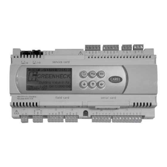
Page 6: Display Use
Display Use The DDC controller is located in the unit control panel. The face of the controller has six keys, allowing the user to view unit conditions and alter parameters. The DDC controller is pre-programmed with easy to use menus. To change the display contrast, hold the Enter and Escape button while pressing the up and down arrows. A remote mounted display is also available, which connects via the J10 port. A six wire patch cable is needed. -
Page 7: Example Of Alarms
Examples of Alarms If an alarm occurs, the button will glow red on the controller and the remote display (if installed). Alarms To view alarm, press the button once. This will display the most recent Press DOWN to review alarm. Press the button again to reset the alarm. -
Page 8: Main Menu Overview
Main Menu Overview The DDC controller will revert to a default main menu loop. This loop includes several screens to view the operating conditions of the unit. Scroll through the menu screens by using the keys. Screens with a dashed line border are dependent upon an optional accessory and may not always appear. TIME DATE UNIT## he iniTial menu screen displays The program version uniT code and... - Page 9 Heating Status eaT and reheaT operaTion is displayed if equipped Heater Control displays the proportional percentage of the heater analog Heater Control: 000% Hot Gas Reheat: 000% output. Staged reheat is: Electric Heater: The Heater Control % is proportional to the 0-10 VDC signal Compressor: being sent to the SCR controller, located in the electric heater control center.
-
Page 10: Menu Overview
Cold Coil T: ##.# 17 ..32 Unit Status Service a. Information Information Information pCO Type: pCO3 Small Greenheck Fan Total Flash: ####KB Code: XXXXXXXXX00 Ram: ####KB Ver.: 1.04 ##/##/## Built-in type:... - Page 11 Menu Overview Press to enter menus. Service c. BMS Config Service Password BMS Configuration MODBUS SETUP MSTP SETUP TCP/IP SETUP TCP/IP SETUP BACnet Read/Write Instance: 77000 Instance: 77000 Function: Read DNS 1: ###.###.### Baudrate 38400 IP set by: DHCP Protocol: None Address: Update? DNS 2: ###.###.### MAC Addr: 172.016.000.001...
-
Page 12: Menus
Menus The controller is equipped with several menus to help guide users with altering program parameters. The following menus can be accessed by pressing the key. To enter the desired menu, press the key. The On/Off Unit menu allows the user to view the detailed On/Off status of the On/Off Unit controller. The unit ships from the factory in a disabled state. - Page 13 Supply Reset Limits his screen displays The minimum and maximum supply air TemperaTure limiTs This screen only appears if the unit is connected to a room temperature sensor. Supply Min: 55.0°F Supply Max: 90.0°F The supply air temperature will be controlled within the Supply Min and Supply Max limits to maintain room temperature set point.
- Page 14 Dehumidification lock his screen displays The TemperaTure difference aT which The . (f = 10°f) dehumidificaTion mode is locked ouT acTory efaulT This screen only appears if the unit is equipped with cooling. Lockout dehumidification until outside air is 10.0°F above This setting prevents the unit from operating in dehumidification mode when the cold coil set point.
-
Page 15: Clock/Scheduler
The Clock/Scheduler menu allows the user to view and alter the time and date. Clock/Scheduler The user can also add up to seven schedules for occupancy requirements. Clock lock screen allows The user To adjusT The Time and daTe Day: Monday Date: 01/31/10... -
Page 16: Board Switch
The a. Information conTroller and The program loaded on The conTroller Information Code: Controller setup code determines functionality of program. When Greenheck Fan contacting the factory, please reference this code. Code: GMY10000X00 Ver.: 1.04 06/01/11... - Page 17 Wheel Preheat Override his screen allows The user To override The energy recovery wheel preheaTer Energy Recovery Wheel This screen only appears if an electric preheat frost control was provided with the Preheat Control: Auto unit. Preheater: his screen allows The user To override The cooling operaTion Cooling Override This screen only appears if a cooling operation was provided with the unit.
-
Page 18: Bms Config
i/o m I/O Manual Management his screen allows The user To enTer The anual anagemenT menu The Manual Management menu allows the user to manually control the I/O END OF OVERRIDE MENU of the controller. The user can manually input values for the analog inputs Press ENTER to go to and digital inputs. The user can also manually control the analog outputs I/O Manual Management and digital outputs. - Page 19 msTp his screen allows The user To adjusT parameTers MSTP SETUP This screen only appears if the selected BMS protocol is set to BACnet MSTP and Instance: 77000 BACnet Plugin = YES. Baudrate 38400 MAC Addr: If a BACnet MSTP card has been installed, the default parameters can be MaxMasters: changed via the controller display.
-
Page 20: Service Settings
Unit BMS Control his screen allows The user To quickly enable The To conTrol uniT operaTion Unit Start/Stop: This screen appears if the unit is equipped with a BMS communication card. Temp Setpoint: Local The factory default configuration is for a non-BMS controlled unit. To allow Occupancy: Input ID6 the BMS to start/stop the unit, change set point and occupancy, alter the... -
Page 21: Manufacturer
Configuration menu allows the user to change the setup code for the unit, enable Manufacturer Scheduling, Holidays, expansion I/O and change Field Card settings. Users are welcomed to enable Scheduling and Holidays. However, code changes and a. Configuration expansion I/O enabling are to be done under factory advice only! Unit Code his screen displays and allows adjusTmenT of The This code is set from the factory to operate the components selected with Select DDC configuration the unit. -
Page 22: Factory Settings
The Factory Settings menu allows adjustment of parameters that are critical for Manufacturer proper unit operation. Adjustment of these parameters is only recommended with c. Factory Settings factory guidance. To access the Factory Settings menu, enter the manufacturer password (Default=1000). Economizer Controller his screen allows The adjusTmenT of parameTers for The economizer funcTion... - Page 23 Compressor Timers his screen displays The compressor minimum Times This screen only appears if DX cooling was provided with the unit. Minimum ON: The compressor minimum ON/OFF times prevents short cycling of the Minimum OFF: 180s compressors. Between Stages: his screen displays when each compressor in a single or dual sTage Compressor Staging uniT will engage disengage...
- Page 24 Hot Gas Flush Setup his screen allows adjusTmenT of The hoT gas flush sysTem This screen appears if hot gas reheat with flush was provided (except heat pump). Cycle: 30minutes The hot gas flush cycle is designed to provide a momentary flush of the hot Duration: 1minutes gas reheat system.
-
Page 25: Initialization
Fan Delay his screen allows adjusTmenT of The Time delay before The exhausT fan when The supply fan sTarTs Time delay between starting This screen only appears if an energy wheel was provided with the unit. of supply & exhaust fans. The delay between the starting of supply and exhaust fans reduces the startup Fan delay: amp draw of the unit. The exhaust fan engages first, allowing the energy... -
Page 26: Points List
Points List Modbus-RTU/TCP/IP BACnet IP/Ethernet BACnet MSTP LonWorks FTT-10A Type Read Description (Unit to BMS signal) Network Address: 1 Device Instance: 77000(default) Write Address Address Name Units NV_Index Name NV Type (BMS to Unit signal) 40002 A001 °F nvoOutsideTemp 105 Analog R Outdoor Air Temp (###.#°F) 40003 A002 °F... -
Page 27: Auxiliary I/O (Pcoe)
Auxiliary I/O (pCOe) The pCOe is an Auxiliary I/O module that can be Digital Inputs Linked Analog Inputs (NTC, 0/1VDC, 0/20mA, 4/20mA, 0/5VDC) used to monitor additional statuses within the unit. The pCOe allows the user to view: 24 VAC Power • 4 Digital Inputs • 4 Digital Outputs 0/10 VDC Digital Analog Output Outputs • 4 Analog Inputs • 1 Analog Output Communication... -
Page 28: Troubleshooting
Troubleshooting Display is hard to read. Unit Controller Display: Hold ESC and ENTER at the same time, while pressing DOWN or UP to adjust display contrast. Remote Display: Hold ALARM, PRG, and ESC at the same time, while pressing DOWN or UP to adjust display contrast. Remote display panel Hold DOWN, UP and ENTER for 4 seconds. Set the display address displays “NO LINK” or... -
Page 29: Bacnet Mstp Quick Start
BACnet MSTP Quick Start The card is loaded with the following default BACnet 4. Once desired parameters have been entered, go MSTP parameters. to BACnet Read/Write screen. Change Function to Write and Update? to YES. Parameter Factory Minimum Maximum 5. Reboot the controller by cycling power to the unit. Device Instance 77000 4194303... -
Page 30: Bacnet Ip/Eth Quick Start
BACnet IP/Eth Quick Start *The BACnet IP/Eth card is configured for DHCP 6. V iew TCP/IP parameters. If changed values did from the factory. not save, contact the factory. To view the current parameters, go the BMS Config The communication card MAC address menu within the controller by pressing the key. -
Page 31: Maintenance Log
Maintenance Log Date __________________ Time _____________ AM/PM Date __________________ Time _____________ AM/PM Notes:___________________________________________ Notes:___________________________________________ _________________________________________________ _________________________________________________ _________________________________________________ _________________________________________________ _________________________________________________ _________________________________________________ _________________________________________________ _________________________________________________ Date __________________ Time _____________ AM/PM Date __________________ Time _____________ AM/PM Notes:___________________________________________ Notes:___________________________________________ _________________________________________________ _________________________________________________ _________________________________________________ _________________________________________________ _________________________________________________ _________________________________________________ _________________________________________________ _________________________________________________ Date __________________ Time _____________ AM/PM... -
Page 32: Warranty
Warranty Greenheck warrants this equipment to be free from defects in material and workmanship for a period of one year from the shipment date. Any units or parts which prove to be defective during the warranty period will be replaced at our option when returned to our factory, transportation prepaid.
Need help?
Do you have a question about the 474706 and is the answer not in the manual?
Questions and answers