
Subscribe to Our Youtube Channel
Summary of Contents for Priorclave Q63
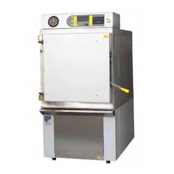
- Page 1 Priorclave Manual 27125322-EN Issue 2 06/06/2012 Operation & Maintenance Manual Q63 Priorclaves Electrically Heated...
-
Page 3: Introduction
06/06/2012 Introduction Priorclave autoclaves are a range of general-purpose laboratory autoclaves intended primarily for media preparation, the making safe of ordinary laboratory and pathological waste and other apparatus sterilisation purposes. The autoclaves are manufactured to a high standard and feature a number of patented innovative design features. -
Page 4: Symbols Used In This Manual And Their Meanings
Symbols used in this manual and their meanings WARNING: Mechanical Hazard In this manual, warnings draw attention to the potential for Danger to personnel up to and including risk of severe injury or death. Each Mechanical Hazard Warning is emphasised by the icon to the left. -
Page 5: Important Notices And Warnings
Always wear gloves a facemask and adequate protective clothing when unloading an autoclave and ensure that the workload does not exceed safe limits. Priorclave are pleased provide training for operators in the use of their autoclaves at a small extra charge. - Page 6 Priorclave Ltd. cannot be held responsible for hazards or damage resulting from work carried out on the pressure system including its closure components by untrained or unauthorised personnel.
- Page 7 Priorclave Manual 27125322-EN Issue 2 06/06/2012 Autoclaves for sterilisation in laboratories Conformity assessment modules B1 + D of the European Pressure equipment directive have been applied to ensure compliance with the essential safety requirements. A “Declaration of Conformity” in accordance with the above standards has been made and is on file at: Priorclave Ltd.
-
Page 8: Eu Declaration Of Conformity
London, SE28 0AB, UK Equipment Description: Priorclave Laboratory autoclaves – Q63 series, with Tactrol microprocessor control system. Model Numbers: PS/Q63/EH320. For direct steam heated variants substitute S for E. All models may be suffixed DBL to denote double entry versions Conformity Data: Directive... -
Page 9: Table Of Contents
Layout Diagram ............................ 9 Operating Summary ........................... 10 Cycle Abort and Thermal Lock Override ....................11 Preparing Your Priorclave for Use for the First Time ................12 Positioning .............................. 12 Provision of Space and Access for Accessories ..................13 Installation ............................14 Electrical .............................. - Page 10 Maintenance ............................40 Weekly Maintenance ..........................40 Monthly Maintenance ..........................42 Quarterly Maintenance .......................... 42 General Maintenance ..........................44 Specification Table ..........................47 Spares List ............................48 Notes ..............................52 Appendix A - Fault Finding & Rectification Guide ................53 Appendix B - Steam Table ........................
-
Page 11: Layout Diagram
Priorclave Manual 27125322-EN Issue 2 06/06/2012 Layout Diagram Tactrol Reset Switch Location Locking Handle Entry Port Access Panel Location Control Panel Details 7. Time Display & Setting Buttons 1. Cycle Progress Display 8. Program Buttons & Indicators (Optional) 2. Door Button & Indicator 9. -
Page 12: Operating Summary
Before proceeding please check the specification sheet at the front of this manual to establish which options and accessories, if any, are fitted to your Priorclave. This will determine whether you will need to read the instructions for these options later in this manual or in Appendix D. -
Page 13: Cycle Abort And Thermal Lock Override
Priorclave Manual 27125322-EN Issue 2 06/06/2012 Move the locking handle down to Door closing procedure release it from its parked position The locking handle will now spring a) Door unlocked Position Move the locking handle down to lock the autoclave door... -
Page 14: Preparing Your Priorclave For Use For The First Time
Unpack the autoclave and check against the delivery note that all items ordered have been delivered. Any shortages or damage must be reported to Priorclave within 7 days of delivery. Positioning When positioning the autoclave consideration should be given to proper access for servicing and maintenance purposes. -
Page 15: Provision Of Space And Access For Accessories
Priorclave Manual 27125322-EN Issue 2 06/06/2012 Floor loading A 700 litre autoclave weighs in the region of 1000kg. Particularly in the case of refurbishment of an older building it will be necessary to consider the strength of the floor on which the autoclave is stood. -
Page 16: Installation
Installation Electrical Details - Rear Left of Autoclave Electrical To connect your Priorclave to the power supply simply connect a suitable cable from your isolator to the isolator on the back of the Isolator Box autoclave. In many cases the isolator will already be connected via a suitable cable and plug. -
Page 17: Drainage And Exhaust Gas Ventilation
– making sure to include the autoclave serial number in your correspondence. If a cable and plug are not fitted then your Priorclave can be wired as shown in the diagram below. 3 Phase - 10.5 kW Heating The power supply should be a 3 phase and neutral isolated supply, rated at 15 Amps per phase and connected to the isolator as in the diagram below. - Page 18 The drain and vent pipe should be in place prior to commencement of installation by Priorclave. It will then be possible to make connections from the autoclave directly into the...
- Page 19 It is Priorclave’s preferred policy to direct the safety valve outlet to discharge to the floor at the rear of the autoclave, however some establishments prefer safety valve outlets to be piped to a high level outside the building.
- Page 20 level of isolation (such as a deep trap) is required to prevent the cross flow of steam between the drains. The drip tray and water tank overflow can be connected to an open tundish if desired. This has the advantage of making any discharge from the overflow visible, which is in accordance with water bylaws.
-
Page 21: General
Priorclave Manual 27125322-EN Issue 2 06/06/2012 up to category 5. Separate header tanks for each of these functions are provided allowing the automatic water fill tank to be fed from a treated water supply, and the vacuum pump to be fed from an untreated supply to economize on the use of treated water if required. -
Page 22: Initial Commissioning
If commissioning has been ordered with the autoclave this will be carried out by a Priorclave technician otherwise follow this simple procedure to check the operation of your Priorclave. -
Page 23: Full Commissioning And Performance Qualification
Setting thermal lock release temperature to suit your particular load, to eliminate unnecessary cooling time whilst ensuring safety. If you feel that any or all of the above would be of use to you then please contact Priorclave Service. -
Page 24: Operation
Operation Before using your Priorclave for the first time check that the circuit breakers and the isolator (at the back of the autoclave) are switched on and that the water supply (if required) is available and turned on. Before proceeding please check the specification sheet at the front of this manual to establish which options and accessories, if any, are fitted to your Priorclave. - Page 25 Priorclave Manual 27125322-EN Issue 2 06/06/2012 Checking Water Level. The autoclave uses immersion heaters in a reservoir of water behind the autoclave weir to raise steam. The heaters are protected from boiling dry by a low water cut-out. If the water level falls below the sensor the autoclave shuts down, the low water warning indicator is lit and fault code F004 is shown in the temperature display.
- Page 26 If you have an interest in any of the options mentioned above, which can quite easily be retro- fitted, please contact Priorclave Technical Services Department. In conclusion, when setting up the autoclaving cycle a large safety margin should be allowed within the settings.
-
Page 27: Automatic Timed Free-Steaming
Priorclave Manual 27125322-EN Issue 2 06/06/2012 Automatic Timed Free-Steaming What is free-steaming? Incorporating a period of free-steaming into a cycle can improve air removal in difficult loads and/or reduce temperature lag between the load and the autoclave, reducing process time at higher temperatures. -
Page 28: Load Sensed Process Timing
Load Sense Thermocouples The load sensed process timing option utilises a thermocouple connected directly to the main processor board. Replacement thermocouples are available from Priorclave. See Maintenance - for details on thermocouple replacement. Rapid Cooling A fan is fitted into the bodywork of the autoclave to direct cool air over the autoclave vessel. -
Page 29: Media Warming
Priorclave Manual 27125322-EN Issue 2 06/06/2012 Immediate start - The cooling fan does not operate at all during the cycle. Left hand indicator lit. - 1 press of the cooling button. The cooling fan starts as soon as the cooling stage is reached. - Page 30 It is strongly recommended that to achieve optimum performance from Priorclaves fitted with vacuum options that commissioning and/or load validation tests are carried out by a trained Priorclave engineer. If no particular programs have been specified your autoclave will be factory set with the following programs:...
-
Page 31: Multi Program Memory Options
The indicators on the left are for programs 1 to 5 and those on the right for programs 6 to 10. If the Priorclave has been specified with a five program memory only the first five programs will be active. As each program number is selected, the indicator illuminates and the previously selected indicator is cancelled. -
Page 32: Vent Button
Pre-Cycle Vacuum (if fitted and selected) Heat-up to freesteam temperature Freesteaming Heat-up to Process Temperature Process Time Cooling Media Warming in Operation (if selected) Cycle Complete The first segment of the cycle status indicator bar will illuminate and the autoclave will now gradually heat up to process temperature. -
Page 33: Cooling
Priorclave Manual 27125322-EN Issue 2 06/06/2012 expected will indicate entrapped air in the autoclave. If for any reason the temperature is forced outside of a pre-set band, or power to the autoclave is removed during the process time, the cycle will abort and the fault indicator will illuminate and a fault code of either F005 or F006 will be shown in the temperature indicator. -
Page 34: Cycle Complete
Under certain cycle abort or failure conditions the thermal safety lock can latch in the locked condition. This is because the control system will always go to the safest condition if there is any uncertainty about the cycle end circumstances. To overcome this simply go through the door open or close procedure using the thermal lock override key. -
Page 35: Changing Date & Time
Priorclave Manual 27125322-EN Issue 2 06/06/2012 Changing Date & Time A number of additional control system settings can be accessed via a “Hidden Menu”. To access these settings turn & hold the thermal lock key in the override position. Press the time up or down keys. -
Page 36: Operation With Options & Accessories
Operation with Options & Accessories The following descriptions detail how to operate and gain maximum benefit from the options and accessories that may be fitted to your Priorclave. Setting Lock Keyswitch Option Fitted on Priorclaves without program memory to give an optional level of security this keyswitch has two settings only, which are equivalent to positions 1 &... -
Page 38: Vent Filter
When fitted to the autoclave this system ensures that air drawn into the autoclave during the cooling stage of the cycle is first passed through a bacteriological air filter. This filter is fitted at the back of the autoclave. The filter should be regularly changed to maintain its effectiveness Vent Filter When fitted to the autoclave this system passes all autoclave discharge through a filter fitted inside a pressurisable stainless steel housing. -
Page 39: Accelerated Media Cooling
Unless specified otherwise before delivery of the autoclave or set up during the commissioning process the Media cooling function is set to operate by default with program It can easily be re-set to operate on different programs by a Priorclave Engineer or your local approved Priorclave representative. -
Page 40: Warning Indicators And Fault Codes
If fault code F000 appears it may be cleared by the method described below. If the fault code will not clear, or continues to re-appear then the user cannot correct the fault. In such a case please contact Priorclave service or your local Priorclave approved service agent. - Page 41 Priorclave Manual 27125322-EN Issue 2 06/06/2012 F010 Air detector input activated. If fitted the air detector system has detected an over pressure condition symptomatic of excess air remaining in the load. F011 Printer Timeout / Malfunction. The control system has nor received confirmation from the printer within its pre-set timeout.
-
Page 42: Maintenance
Ensure that any electrically locked doors are open before disconnecting power. In the event of any difficulty or doubt about any maintenance or service procedure contact Priorclave Limited or your nearest Priorclave approved agent or supplier immediately. Weekly Maintenance Low Water Probe To ensure protection from boiling dry the probe sensor tip should be scrubbed clean to ensure good contact. - Page 43 Although the design and material of Priorclave Gaskets makes them extremely durable and long-lasting it is advisable to regularly inspect the condition of the gasket and to change the gasket at the first sign of damage or wear and, if applicable, after 3 years of use.
-
Page 44: Monthly Maintenance
Monthly Maintenance To be carried out in addition to weekly maintenance programme. General Operation The general operation and performance of the autoclave should be observed frequently, and any fault or defect reported or rectified immediately, and entered into the notes section of the operating manual. - Page 45 Priorclave Manual 27125322-EN Issue 2 06/06/2012 Priorclave Limited or your local agent). Should the top cap prove particularly tight the complete valve should be removed from the pressure vessel and the body gripped in a vice to remove the cap, as excessive localised pressure could damage the pressure vessel and/or its pipe-work.
-
Page 46: General Maintenance
Door Assembly Door Closed Micro-switch-Detail Locking Solenoid & Micro-switches-Detail Locking Solenoid * With door cover removed, check the locking pin and solenoid for freedom of movement. If necessary the screws should be tightened and the solenoid re-aligned with the pin. Filters (If fitted) The condition of air intake filters should be inspected regularly. - Page 47 Priorclave Manual 27125322-EN Issue 2 06/06/2012 through a standard cycle. When the process time has commenced check the reading shown by the temperature display against that of the thermometer or recorder. Should there be a disparity of readings in the order of that previously noted then it is likely that the Temperature Controller is at fault and needs resetting.
- Page 48 (such as bath sealant) to the joint to assist sealing. The joint should be checked for leaks when the autoclave is first pressurised. Replacement bungs are available from Priorclave, or alternatively use a No. 21 (large port) or a No. 13 (small port) silicone rubber bung and trim the top end by about 5mm.
-
Page 49: Specification Table
Priorclave Manual 27125322-EN Issue 2 06/06/2012 Specification Table Model : PS/Q63/EH320 Capacity 320 Litres Dimensions Machine (wxd) 760x1280mm Minimum Installation Space 960x1480x1600mm Required (wxdxh) Weight Unloaded 300kG With water charge 325kG Door 85kG Pressure Vessel 165kG Electrical Power Supply Required... -
Page 50: Spares List
Spares List A full selection of spares are available from Priorclave Service or your local Priorclave dealer. Please give your autoclave serial number when ordering parts. A selection of the more commonly used parts is listed below: Description Part Number 15mm (½”) Strainer... - Page 51 Priorclave Manual 27125322-EN Issue 2 06/06/2012 Door Closed Microswitch MSA/DCL/QCS Door Gasket GAS/ACS/630 Door Lock Microswitch MSA/CAN/VER Door Locking Solenoid SOL/QCS/001 Heater HTR/MID/C40 Hinge Block Shim SHM/Q63/HNG Large Cable Port Bung SBG/ACS/022 Locking Clamp Shim SHM/Q63/CLA Low Water Probe Electrode...
- Page 52 Pressure Gauge PSG/ACS/001 Pressure Switch PSS/SWI/001 Printer Paper Roll ZZZ/ROL/005 Printer Ribbon Cassette ZZZ/RIB/002 Safety Valve - Complete VSC/ACS/022 Setting Lock Keyswitch KEY/SLK/001 Single Pole Circuit Breaker 6A MCB/ACS/006 Small Cable Port Bung SBG/ACS/015 Thermal Lock Keyswitch KEY/TLK/002...
- Page 53 Priorclave Manual 27125322-EN Issue 2 06/06/2012 Vent Valve 28mm (1in BSP) VVC/RSC/028 Wandering Thermocouple Probe PRB/ACS/004...
-
Page 54: Notes
Notes... -
Page 55: Appendix A - Fault Finding & Rectification Guide
Priorclave Manual 27125322-EN Issue 2 06/06/2012 Appendix A - Fault Finding & Rectification Guide Symptom Possible Cause Possible Solution No Power Power switched off at isolator Check Circuit Breaker Tripped Reset and check cause Electrical Failure Call Engineer Cycle does not commence when Door is not closed properly Open &... - Page 56 If you have any doubts or If you do not feel competent to carry out any of the above procedures then do not hesitate to call Priorclave Service on 020 8316 6620 or your nearest Priorclave approved service agent.
-
Page 57: Appendix B - Steam Table
Priorclave Manual 27125322-EN Issue 2 06/06/2012 Appendix B - Steam Table Autoclave Temperature Pressure (BarG) 0.00 0.20 0.43 0.69 0.99 1.06 1.13 1.25 1.35 1.55 1.70 1.86 2.04 2.21 2.40 2.60 Correct Correlation between Temperature and Pressure shows correct operation of the autoclave and that air purging is satisfactory. -
Page 59: Appendix C - Wiring Diagrams
Priorclave Manual 27125322-EN Issue 2 06/06/2012 Appendix C - Wiring Diagrams The following Circuit Diagrams show the wiring configuration for the standard models and in addition for the more popular options and accessories. For Options and Accessories not covered by these standard drawings supplementary drawing sheets will be issued and these should be included within the manual and/or are available from Priorclave. -
Page 60: Standard Non-Vacuum Models
Standard Non-Vacuum Models... - Page 61 Priorclave Manual 27125322-EN Issue 2 06/06/2012...
-
Page 62: Standard Vacuum Models
Standard Vacuum Models... - Page 63 Priorclave Manual 27125322-EN Issue 2 06/06/2012...
-
Page 65: Appendix D - Pipework Schematics
Priorclave Manual 27125322-EN Issue 2 06/06/2012 Appendix D - Pipework Schematics The following Pipework Schematics show the wiring configuration for the standard models and in addition for the more popular options and accessories. For Options and Accessories not covered by these standard drawings supplementary drawing sheets will be issued and these should be included within the manual and/or are available from Priorclave. -
Page 66: Non Vacuum Models
Non Vacuum Models 64 ... -
Page 67: Vacuum Models
Priorclave Manual 27125322‐EN Issue 2 06/06/2012 Vacuum Models ... -
Page 69: Appendix E - Other Options Fitted
Priorclave Manual 27125322-EN Issue 2 06/06/2012 Appendix E - Other Options Fitted... -
Page 71: Liquid Ring Vacuum Pump Vz 30/50 Extracts From Operating Instructions
Regulations Sixteenth Edition. Other power supplies If a cable and plug are not fitted then your Priorclave can be wired as shown in the diagram below. Your Priorclave can be wired in one of two electrical configurations depending on the power supply available. - Page 72 As you are powering up the autoclave for the first time, the autoclave will be in a low water condition, the low water indicator should now be lit and the error code F004 will show in the temperature display. You may ignore this at this stage as opening the autoclave and filling it with water will reset this error.
Need help?
Do you have a question about the Q63 and is the answer not in the manual?
Questions and answers