Advertisement
Table of Contents
- 1 Verify the Grid Voltage to Match with Microinverter Rating.
- 2 Attach the Apsystems Microinverters to the Racking.
- 3 Connect the Apsystems Microinverter Cables to the AC Bus Cable.
- 4 Install a Protective End Cap at the End of AC Bus Cable.
- 5 Install the AC Branch Circuit Junction Box.
- 6 Connect the Cables to the Branch Junction Box.
- 7 Complete the Apsystems Installation Map.
- 8 Start the Operation.
- Download this manual
Please scan the QR code to get
mobile app and more support
to help the installation.
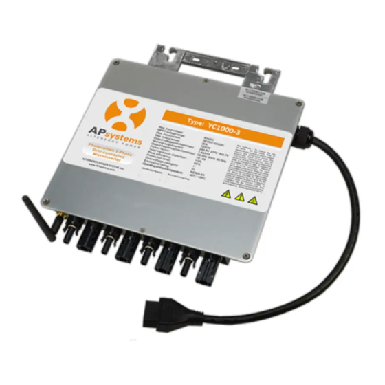
APsystems YC1000-3-NA Microinverter Quick Installation Guide
The sketch of YC1000-3 support system.
All the PV modules are placed into two lines. Then put a YC1000-3 in the middle of the two lines and make
sure it is easy to connect with four PV modules which are next to it, as well all the cables.
Step 1.
Verify the grid voltage to match with microinverter rating.
Step 2.
Lay the AC bus according to the arrangement of APsystems Microinverter.
Step 3.
Attach the APsystems Microinverters to the racking.
NOTE: Do not place the inverters (including DC and AC connectors) where exposed to the sun, rain or snow,
even gap between modules. Allow a minimum of 3/4''(1.5cm.) between the roof and the bottom of the
Microinverter to allow proper air flow.
Step 4.
Attach the antenna to the microinverter, and keep the antenna vertical to the
earth.
Step 5.
Connect the APsystems Microinverter cables to the AC bus cable.
NOTE: AC connector interface as follows,
from left to right PE, N, L3, L2, L1.
NOTE: Cover all unused T connectors with
sealing caps to protect the T connectors.
2016/12/20
1
REV1.2 Quick Installation Guide
Advertisement
Table of Contents

Related Manuals for APsystems YC1000-3-NA


Summary of Contents for APsystems YC1000-3-NA
- Page 1 Step 1. Verify the grid voltage to match with microinverter rating. Step 2. Lay the AC bus according to the arrangement of APsystems Microinverter. Step 3. Attach the APsystems Microinverters to the racking. NOTE: Do not place the inverters (including DC and AC connectors) where exposed to the sun, rain or snow, even gap between modules.
- Page 2 Each APsystems microinverter has two removable serial number labels. Peel labels off, affix one to the respective location on the APsystems installation map, and affix another to the PV module frame which is easy to see. Use the Scanning Gun to scan the serial numbers on the map into the computer or scan by mobile phone with APsystems ArrayApp, then complete the setting (see ECU manual).
Need help?
Do you have a question about the YC1000-3-NA and is the answer not in the manual?
Questions and answers