Table of Contents
Advertisement
Quick Links
Advertisement
Table of Contents

Related Manuals for Polycom KIRK Wireless Server 500


Summary of Contents for Polycom KIRK Wireless Server 500
- Page 1 Polycom ® KIRK Wireless Server 500 User Guide 14174600, Ed.3...
- Page 2 KIRK Wireless Server 500 User Guide Welcome Thank you for your purchase of the KIRK Wireless Server 500 (KWS500). The KWS500 is a telecommunications computer that is wired to your host PBX and serves as a radio base station for KIRK Handsets .
- Page 3 [Italian]: dalla direttiva 1999/5/CE. Hér með lýsir Polycom (UK) Ltd yfir því að KIRK 500 Server er í samræmi Íslenska við grunnkröfur og aðrar kröfur, sem gerðar eru í tilskipun 1999/5/EC...
- Page 4 Português requisitos essenciais e outras disposições da Directiva 1999/5/CE. [Portuguese]: Slovensko Polycom (UK) Ltd izjavlja, da je ta KIRK 500 Server v skladu z bistvenimi [Slovenian]: zahtevami in ostalimi relevantnimi določili direktive 1999/5/ES. Slovensky Polycom (UK) Ltd týmto vyhlasuje, že KIRK 500 Server spĺňa základné...
- Page 5 KIRK Wireless Server 500 User Guide Explosive Device Proximity Warning Warning Do not operate your wireless network device near unshielded blasting caps or in an explosive environment unless the device has been modified to be especially qualified for such use.
- Page 6 KIRK Wireless Server 500 User Guide The WEEE Marking on this equipment indicates that the product must not be disposed of with unsorted waste, but must be collected separately. Safety Instructions Before using your telephone equipment, you should always follow basic safety instruction to reduce the risk of fire, electrical shock, and injury to persons, and damage to property.
- Page 7 Copyright © 2007 Polycom, Inc. All rights reserved. The information in this document is subject to change without notice. Polycom, Inc. reserves the right to make changes in design or components as progress in engineering and manufacturing may warrant. The statements, configurations, technical data, and recommendations in this document are believed to be accurate and reliable, but are presented without express or implied warranty.
-
Page 8: Table Of Contents
System Capacities Installation Overview Installation Requirements 2. Site Preparation Site Preparation Step-by-Step Completing Site Preparation 3. Installing the KIRK Wireless Server 500 Hardware Installation Step-by-step: Opening the KWS500 Inside the KWS500 Wiring the KWS500 Mounting the KWS500 KWS500 Base Station LED Conditions 4. -
Page 9: Getting Started
KIRK Wireless Server 500 User Guide Getting Started This guide describes how to: 1. Prepare for a successful installation. 2. Find a suitable location for your KWS500. 3. Run cabling from the host PBX to the chosen location. 4. Install the KWS500. -
Page 10: Hardware Summary
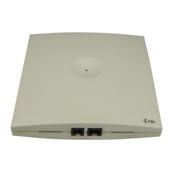
KIRK Wireless Server 500 User Guide Hardware Summary Please remove all boxes from the master container and verify that all parts are included in the shipment before continuing with this guide. Inside the master container you will find several boxes containing: (part number) KWS500 Central Control Unit and 1.9 GHz radio Base Station (0236 3900) (See fig. -
Page 11: Tools And Materials
KIRK Wireless Server 500 User Guide Fig. 1 KWS500 with Mounting Hardware Tools and Materials The tools and materials listed are required for a normal installation of a KWS500. Though not all tools may be used on a given installation, use of each of these tools may be necessary to complete the installation. -
Page 12: System Capacities
KIRK Wireless Server 500 User Guide Plastic cable ties Diagonal wire cutters Telephone cable insulation strippers Punchdown tool matching all PBX termination blocks used at installation site # T10 Torx driver Level Drill #1 and #2 Phillips screwdrivers Wire strippers (capable to strip 24 AWG... -
Page 13: Installation Overview
KIRK Wireless Server 500 User Guide Cat. 3 cabling Analog lines KWS500 (up to 8) Intermediate Distribution Frame Repeaters Power (up to 6) Supply Fig. 2 Installed KWS500 System KIRK Handsets (up to 8) Installation Overview If you are not familiar with telephone cable installation, please contact your... - Page 14 Cat. 3 cables from the host PBX distribution frame to the KWS500. • Install the KWS500. See Section 3 Installing the KIRK Wireless Server 500. • Subscribe the master handset. See Section 4 or 6, depending on the KIRK Handset model chosen to be the master handset.
-
Page 15: Installation Requirements
KIRK Wireless Server 500 User Guide Mount the KWS500 vertically, at least 6 feet high Fig. 3 Mounted KWS500 Installation Requirements The KWS500 has specific connection requirements and rules for installation. Following these guidelines is necessary for a successful installation. - Page 16 KIRK Wireless Server 500 User Guide programming may be accomplished using a laptop PC with the KIRK Administration Program installed, connected to the KWS500 with the KIRK Programming Cable . Contact your KIRK vendor for more information.) KWS500 Base Station installation do’s and don’ts...
-
Page 17: Site Preparation
Plan the wiring of the KWS500 using the Wiring Table (see Appendix) and the Cat. 3 Cable Color Pair table. • Proceed to Section 3 Installing the KIRK Wireless Server 500. PBX provisioning Your PBX telephone system may require another analog station card, programming, or other preparation in order to support the KIRK Handsets. -
Page 18: Completing Site Preparation
Verify that each step of site preparation is complete and the site is ready for installation of the KWS500 system. Proceed to Section 3 Installing the KIRK Wireless Server 500. Connection point for wiring between two electrical devices. For instance, a port is one of eight pairs of connectors on the KWS500 termination block. -
Page 19: Installing The Kirk Wireless Server 500
KIRK Wireless Server 500 User Guide Installing the KIRK Wireless Server 500 Prior to installing the KWS500, the Cat. 3 telephone cabling from the host PBX to the installation location must be in place. (If you are performing a preliminary installation with temporary cabling to test radio coverage, connect it to any available phone line, such as a wall jack.) - Page 20 KIRK Wireless Server 500 User Guide • Insert a mini screwdriver into the top hole (1) on the left side of the termination block (port ) (fig. 7a, 8). • Press down so as to open the spring-loaded clamp in the bottom hole (3). (fig. 7b, 8).
Need help?
Do you have a question about the KIRK Wireless Server 500 and is the answer not in the manual?
Questions and answers