
Related Manuals for Winmate IB70


Summary of Contents for Winmate IB70
-
Page 1: User Manual
IB70 Motherboard Mini-ITX Fanless SBC with Bay Trail Intel ® Celeron Processor, LVDS, VGA, Dual Giga Ethernet, and Mini-PCIe Interface V110 User Manual Version 1.4 Manual Number: 9171111I101Z... -
Page 2: Preface
IB70 Motherboard User Manual Preface Copyright Notice No part of this document may be reproduced, copied, translated, or transmitted in any form or by any means, electronic or mechanical, for any purpose, without the prior written permission of the original manufacturer. - Page 3 IB70 Motherboard User Manual Packing List Before using this Motherboard, please make sure that all the items listed below are present in your package: IB70 Motherboard User Manual & Driver CD Optional Accessories: Power Cord If any of these items are missing or damaged, contact your distributor or sales representative immediately.
- Page 4 IB70 Motherboard User Manual Safety Precautions Warning! Always completely disconnect the power cord from your chassis whenever you work with the hardware. Do not make connections while the power is on. Sensitive electronic components can be damaged by sudden power surges. Only experienced electronic personnel should open the PC chassis.
- Page 5 IB70 Motherboard User Manual Safety and Warranty Please read these safety instructions carefully. Please keep this user- manual for later reference. Please disconnect this equipment from any AC outlet before cleaning. Do not use liquid or spray detergents for cleaning. Use a damp cloth.
-
Page 6: Revision History
IB70 Motherboard User Manual Revision History Version Date Note Author 2014.07.04 Initial Draft Jimmy Chen 2014.08.15 Block Diagram revision Jimmy Chen 2014.09.01 Add OS Selection Jimmy Chen Add USB 3.0 Driver 2015.05.08 Jimmy Chen Installation Corrected: Jimmy Chen, PIN Assignments , BIOS 2015.12.14... -
Page 7: Table Of Contents
IB70 Motherboard User Manual CONTENTS PREFACE ....................II CHAPTER 1 GENERAL INFORMATION ..........2 1.1 I ..................2 NTRODUCTION 1.2 F ....................2 EATURES 1.3 M ..............3 OTHERBOARD PECIFICATIONS CHAPTER 2 HARDWARE INSTALLATION ..........8 2.1 M (SO-DIMM) I ........... - Page 8 IB70 Motherboard User Manual 3.2.4 Security Menu ....................65 3.2.5 Boot Configuration ..................66 3.2.6 Save & Exit ....................67 3.3 U ........70 SING ECOVERY IZARD TO ESTORE OMPUTER CHAPTER 4 DRIVER INSTALLATION ..........73 4.1 I ............73...
-
Page 9: Chapter 1 General Information
IB70 Motherboard User Manual General Information This chapter includes the IB70 Motherboard background information. Sections include: Introduction Features Motherboard Specifications... - Page 10 24-bit Dual-Channel LVDS. With all of the integrated features, IB70 SBC is designed to satisfy most of the applications in the industrial computer market, such as Gaming, POS, KIOSK, Industrial Automation, and Programmable Control System. It is designed in a compact 3.5”...
-
Page 11: Motherboard Specifications
IB70 Motherboard User Manual Motherboard Specifications ® ® CPU Type Intel Celeron Bay Trail-M N2930 CPU Speed 1.83GHz ® Chipset Intel SoC Integrated BIOS AMI 64Mbit Flash Graphic Intel® Graphics Engine LCD interface Dual-Channel 18/24 bit LVDS Up to 1920 x 1080 @ 60Hz... - Page 12 IB70 Motherboard User Manual 1 x 30 pins Connector for eDP 1 x 3 pins digital panel backlight brightness controller 1 x 7 pins digital panel inverter 2 x 2 pins pin-header for Speaker 1 x 20 pins pin-header for LPT port(2X10)
-
Page 13: Otherboard
IB70 Motherboard User Manual Function block (V110) -
Page 14: Otherboard
IB70 Motherboard User Manual Board dimensions (V110) -
Page 15: Chapter 2 Hardware Installation
IB70 Motherboard User Manual Hardware Installation This chapter provides information on how to use jumpers and connectors on the IB70 SBC Motherboard. Be cautious while working with these modules. Please carefully read the content of this chapter in order to avoid any damages. - Page 16 IB70 Motherboard User Manual Chapter 2 Hardware Installation 2.1 Memory Module (SO-DIMM) Installation The IB70 SBC Motherboard provides one 204-pin SODIMM slot. The socket supports up to 4GB DDR3L 1066/1333 SDRAM. When installing the Memory device, please follow the steps below:...
-
Page 17: I/O Equipment Installation
IB70 Motherboard User Manual 2.2 I/O Equipment Installation 2.2.1 12V DC-IN The Motherboard allows plugging 12V DC-IN jack on the board without another ® power module converter under power consumption by Intel Celeron N2930 1.83GHz Processor with Intel SoC integrated. -
Page 18: Audio Function
IB70 Motherboard User Manual 2.2.6 Audio Function The Audio 7.1 channel capabilities are provided by a Realtek ALC886 chipset supporting digital audio outputs. The audio interface includes three jacks: line-in, line-out and mic in. -
Page 19: Jumpers And Connectors
IB70 Motherboard User Manual 2.3 Jumpers and Connectors 2.3.1 Component Side... -
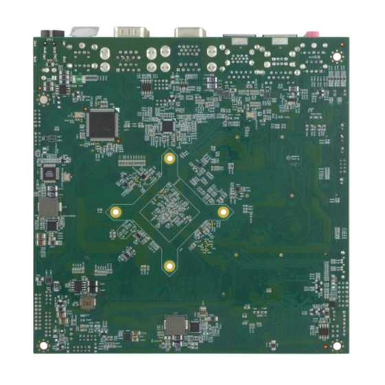
Page 20: Solder Side
IB70 Motherboard User Manual 2.3.2 Solder Side... -
Page 21: I/O Side
IB70 Motherboard User Manual 2.3.3 I/O Side... -
Page 22: Jumper Settings
IB70 Motherboard User Manual 2.4 Jumper Settings This section explains how to set jumpers for correct configuration of the motherboard. A pair of needle nose pliers may be helpful when working with jumpers. If you have any doubts about the best hardware configuration for your... - Page 23 IB70 Motherboard User Manual 2.4.2 Setting Jumpers JP1: Inverter Voltage Select Setting Function 1-2* 12 V *Default JP2: Inverter Enable Select Setting Function 1-2* Control to BLON Normal (Always) *Default JP3: Backlight Control VR Pin № Name Pin № Name...
- Page 24 IB70 Motherboard User Manual JP4: DC Mode Control Selector Setting Function VR knob Control to VRD 2-3* VR knob Control to SBC *Default JP5: From SoC Brightness PWM Voltage Selector Setting Function 1-2* + 3.3V + 5.0V *Default JP6: Brightness Control Selector...
- Page 25 IB70 Motherboard User Manual JP8/JP9: COM Serial Port (RS232/422/485) Select Please refer to JP8/JP9 settings below. RS232 RS422 RS485 10-11 11-12 11-12 For example: At the picture below you can see RS-232, RS-422, RS-485 (J8/J9) jumper setting. To select RS-232 set Jumper 8 Pin 1-2 to the SHORT position, and Jumper 9...
- Page 26 IB70 Motherboard User Manual JP10: VRD Brightness Control Select Setting Function VRD REVERSE - 2-3* VRD FORWARD + *Default JP11: Clear CMOS Setting Function Clear CMOS 2-3* Normal *Default...
-
Page 27: Connectors And Pin Assignment
IB70 Motherboard User Manual 2.5 Connectors and Pin Assignment 2.5.1 Front Side Setting Description The table below shows each of front side connectors and its functions. Label Function Note RTC Battery 2P Wafer, pitch 1.25mm R-Speaker out 1x2 Wafer, pitch 2.0mm L-Speaker out 1x2 Wafer, pitch 2.0mm... - Page 28 IB70 Motherboard User Manual USB2 Internal USB2.0 2x4 Wafer, pitch 2.0mm USB3 Internal USB2.0 2x4 Wafer, pitch 2.0mm 3.3V output 1x2 Wafer, pitch 2.0mm 5V output 1x2 Wafer, pitch 2.0mm 5V output 1x2 Wafer, pitch 2.0mm 12V1 12V output 1x2 Wafer, pitch 2.0mm...
- Page 29 IB70 Motherboard User Manual BT1: RTC Battery Pin № Name Pin № Name CN1: R-Speaker Out Pin № Name ROUT- ROUT+ CN2: L-Speaker Out Pin № Name LOUT- LOUT+ CON1: Panel Power Select...
- Page 30 IB70 Motherboard User Manual Pin № Name 1-2* +3.3V +12V CON2: Backlight Pin № Name Pin № Name Backlight Power Backlight Power Backlight Power Brightness Adjust Backlight Enable Note: Please refer to settings to select POWER RATING COM4: Serial port (RS-232) Pin №...
- Page 31 IB70 Motherboard User Manual CPU_FAN1: CPU FAN Pin1 Pin № Name Pin № Name +12V SENSE ATX12V1: DC-In Pin № Name Pin № Name +12V *Note: Pin 3 is not visible for user...
- Page 32 IB70 Motherboard User Manual Debug 1: Debug Port Pin № Name Pin № Name LPC_AD0 +3.3V LPC_AD1 LPC_AD2 LPC_FRAME LPC_AD3 RESET CLOCK DIMM1: DDR3...
- Page 33 IB70 Motherboard User Manual DIMM2: DDR3 DIDO1: GPIO Pin № Name Pin № Name DOUT3 DOUT1 DOUT2 DOUT0 DINT3 DINT1 DINT2 DINT0 DIN4 DOUT4 DIN5 DOUT5...
-
Page 34: J2: Dp
IB70 Motherboard User Manual J1: VRD Debug Pin № Name Pin № Name +3.3V DATA CLOCK RESET J2: DP Pin № Name Pin № Name DDI1_AUX_DN SMB_DATA DDI1_AUX_DP SMB_CLK DDI1_TX3_DN DDI1_TX3_DP EDP_HPD DDI1_TX2_DN DDI1_TX2_DP DDI1_TX1_DN DDI1_TX1_DP LCDVDD LCDVDD DDI1_TX0_DN LCDVDD... - Page 35 IB70 Motherboard User Manual J3: HDMI Pin № Name Pin № Name TMDS_DATA2+ TMDS_DATA2- TMDS_DATA1+ TMDS_DATA1- TMDS_DATA0+ TMDS_DATA0- TMDS_CLOCK+ TMDS_CLOCK- DDC_CLOCK DDC_DATA Hot Plug Detect...
- Page 36 IB70 Motherboard User Manual LVDS1: LVDS Pin № Signal Name Pin № Signal Name LCDVDD LVDS0_TX0_N LCDVDD LVDS0_TX0_P LCDVDD LVDS0_TX1_N LVDS0_TX1_P LVDS0_TX2_N LVDS0_TX2_P LVDS0_CLK_N LVDS0_CLK_P LVDS0_TX3_N LVDS0_TX3_P LVDS1_TX0_N LVDS1_TX0_P LVDS1_TX1_N LVDS1_TX1_P LVDS1_TX2_N LVDS1_TX2_P LVDS1_CLK_N LVDS1_CLK_P LVDS1_TX3_N LVDS1_TX3_P * Note: Please refer to...
- Page 37 IB70 Motherboard User Manual LPT1: LPT Pin № Name Pin № Name LPT_STB# LPT_PD0 LPT_PD2 LPT_PD1 LPT_PD4 LPT_PD3 LPT_PD5 LPT_PD6 LPT_PD7 ACK# Busy SLCT LPT_AFD# LPT_INIT# ERR# 18-25 LPT_SLIN# MINI PCIE1: WWAN Pin № Name Pin № Name PCIE_WAKE# +3.3V BT_EN +1.5V...
- Page 38 IB70 Motherboard User Manual Wireless_ENABLE PCIE_RESET PCIE_RXM +3.3V PCIE_RXP +1.5V SMB_CLK PCIE_TXM SMB_DATA PCIE_TXP USB_D- USB_D+ +3.3V +3.3V +1.5V +3.3V +3.3V...
- Page 39 IB70 Motherboard User Manual MINI PCIE2: WIFI Pin № Name Pin № Name PCIE_WAKE# 3.3V BT_EN +1.5V CLK_SLOT2_OE# CLK_PCIE_SLOT2_N CLK_PCIE_SLOT2_P 3G_EN PCIE_RESET PCIE2_RXN2 +3.3V PCIE2_RXP2 +1.5V SMB_CLK PCIE2_TXN2 SMB_DATA PCIE2_TXP2 USB_D- USB_D+ 3.3V 3.3V +1.5 V 3.3V 3.3V...
- Page 40 IB70 Motherboard User Manual SATA1: SATA Pin № Name Pin № Name SATA_TXP SATA_TXN SATA_RXN SATA_RXP SATA_PWR1: SATA Power Pin № Name Pin № Name +12V +12V SIM1: Cable connector for SIM-100 Pin № Name Pin № Name VREG_USIM SIM_RESET...
- Page 41 IB70 Motherboard User Manual SSD1: mSATA Pin № Name Pin № Name +3.3V +1.5V SATA_RXP +3.3V SATA_RXN +1.5V SMB_Clock SATA_TXN SMB_Data SATA_TXP +3.3V +3.3V +1.5V SSD_LED# +3.3V...
- Page 42 IB70 Motherboard User Manual USB2: Internal USB2.0 Pin № Name Pin № Name USB_D- USB_D- USB_D+ USB_D+ USB3: Internal USB2.0 Pin № Name Pin № Name USB_D- USB_D- USB_D+ USB_D+...
- Page 43 IB70 Motherboard User Manual 3V1: 3.3V Output Pin № Name +3.3V 5V1: 5V Output Pin № Name 5V2: 5V output Pin № Name 12V1: 12V Output Pin № Name +12V...
- Page 44 IB70 Motherboard User Manual Panel1: OSD Membrane Control Pin № Name Pin № Name +3.3V HDD_LED PWRBTN# GND/ Backlight ADJ+ Reset NC/Backlight ADJ- NOTE: Backlight ADJ+ / Backlight ADJ- optional functions SYS_FAN: SYS_FAN1 Pin № Name Pin № Name +12V...
-
Page 45: I/O Side Setting Description
IB70 Motherboard User Manual 2.5.2 I/O Side Setting Description The table below shows each of I/O side connectors and its functions. Label Function Note AUDIO Line In/Line Out/Mic AUDIO COM1 Serial port (RS232/422/485) D-Sub 9 D-Sub 9 COM3/ COM4 Serial port (RS232/422/485) - Page 46 IB70 Motherboard User Manual COM3, COM4: Serial port (232) Pin № Name Pin № Name LAN1, LAN2: Gigabit Ethernet Pin № Name Pin № Name TX1+ TX1- TX2+ TX2- TX3+ TX3- TX4+ TX4- PS/2: Mouse/Keyboard Pin № Name Pin №...
- Page 47 IB70 Motherboard User Manual 2 USB: USB 2.0 / USB 3.0 Pin № Name Pin № Name USB_D- USB_D+ STDA_SSRX- STDA_SSRX+ GND_DRAIN STDA_SSTX- STDA_SSTX+ USB_D- USB_D+ VGA: Video Graphic Array Pin № Name Pin № Name DDC_DATA DDC_CLOCK Horizontal Sync...
-
Page 48: Chapter 3 Ami Bios Setup
IB70 Motherboard User Manual AMI BIOS Setup This chapter contains BIOS Configuration and OS Recovery information. 3.1 When and How to Use BIOS Setup 3.2 BIOS Functions 3.3 Using Recovery Wizard to Restore Computer... - Page 49 IB70 Motherboard User Manual Chapter 3 AMI BIOS SETUP 3.1 When and How to Use BIOS Setup The BIOS Setup allows users to modify system configurations. To enter the BIOS setup, you need to connect an external USB keyboard, press Del key when the prompt appears on the screen during start up.
-
Page 50: Bios Functions
IB70 Motherboard User Manual Cursor ↑ Moves to the previous item Cursor ↓ Goes to the next item Cursor ← Moves to the previous item Cursor → Goes to the next item You can press the F1, F2, F3, F4, –/+, and Esc keys by connecting a USB keyboard to your computer. - Page 51 IB70 Motherboard User Manual BIOS Setting Description Setting Option Effect System Displays the system Adjustment of Set the language in Language language. [English] is set other language. The up by default. language language in this device is English. System This is current date...
-
Page 52: Advanced Menu
IB70 Motherboard User Manual 3.2.2 Advanced Menu The advanced menu also uses to set configuration of the CPU and other system devices. There are sub menus on the left frame of the screen. Handle advanced BIOS settings page with caution. Any changes can affect the operation of your computer. - Page 53 IB70 Motherboard User Manual BIOS Setting Description Setting Effect Option ACPI Settings Configures ACPI settings Enter Opens submenu F81866 Super IO Configures IO settings Enter Opens Configuration submenu Hardware Monitor Configures Hardware Monitor Enter Opens settings submenu S5 RTC Wake...
- Page 54 IB70 Motherboard User Manual ACPI Settings Advanced Configuration and Power Interface (ACPI) settings allow to control how the power switch operates. The power supply can be adjusted for power requirements. You can use the screen to select options of ACPI configuration. A description of the selected items will appear on the right side of the screen.
- Page 55 IB70 Motherboard User Manual Super IO Configuration You can use the screen to select options for Super IO Configuration, and change the value of the option selected. A description of the selected item appears on the right side of the screen. For items marked with ►, please press <Enter> for more options.
- Page 56 IB70 Motherboard User Manual GPI0 Port Configuration You can use the screen to change GPI0 Port setting. Use these items to set parameters related to PIN3-PIN14 Control. Watch Dog Time Select You can either disable Watch Dog Time Select, or set up the time.Use <Arrow> keys...
- Page 57 IB70 Motherboard User Manual Hardware Monitor You can check PC Health Status parameters such as system temperature, fan speed etc. S5 RTC Wake Settings Wake system from S5 enables or disables system wake on alarm event. It allows you to wake up the system in a certain time.
- Page 58 IB70 Motherboard User Manual Wake system from S5 after fixed time setting Select Fixed Time to set the system to wake on the specified time. Use Navigation Keys to switch among the items: Day, Hour, Minute and Second. Type the desired value in the selected item.
- Page 59 IB70 Motherboard User Manual Wake system from S5 after dynamic time setting Select Dynamic Time to set the system to wake on the current time + increase minute (s). CPU Configuration Press <Enter> to view current CPU configuration and make settings for the following...
- Page 60 IB70 Motherboard User Manual BIOS Setting Description Setting Option Effect Socket CPU This item contains socket Displays Socket Displays Socket Information specific CPU information. CPU Information CPU Information CPU Thermal Thermal control Auto/Disabled Auto/Disable this Configuration function Limit CPUID Limits CPIID Maximum...
- Page 61 IB70 Motherboard User Manual PPM Configuration BIOS Setting Description Setting Effect Option CPU C State Shows CPU C State Report Enabled/ Enable or Disable CPU Report Disabled C state report to OS Max CPU Allows to enter C1E, C3, Enable or Disable CPU...
- Page 62 IB70 Motherboard User Manual Thermal Configuration BIOS Setting Description Setting Option Effect Critical Trip Allows you to set the Temperature Select the temp. Point critical temperature of range the processor chip which automatically reduce the frequency of the processor or turn on throttling (skipping beats).
- Page 63 IB70 Motherboard User Manual IDE Configuration BIOS Setting Description Setting Effect Option Serial- ATA (SATA) Responsible for supporting Enabled/ Enable or disable this chipset drives with SATA Disabled function interface. SATA Speed Allows forcing the speed Gen1 The maximum speed will...
- Page 64 IB70 Motherboard User Manual chipset extended host controller SATA II [IDE] SATA controller will operate in a mechanism similar to a conventional IDE-controller [RAID] Allows combining hard drives in RAID-arrays in order to improve the reliability of data storage, or to increase the speed.
- Page 65 IB70 Motherboard User Manual Miscellaneous Configuration OS Selection This item allows users to select the proper Operating System. BIOS Setting Description Setting Effect Option Windows 8.X Allows user to choose the Enter Use Windows 8.X proper OS. Windows 7 Allows user to choose the...
- Page 66 IB70 Motherboard User Manual CSM Configuration BIOS Setting Description Setting Effect Option The Compatibility Support Module Enabled/ Enable or Support (CSM) is a component of the UEFI Disabled disable the firmware that provides legacy Compatibility BIOS compatibility by emulating a...
- Page 67 IB70 Motherboard User Manual ROM is booted option ROMs are booted Legacy Storage Specifies which Storage option UEFI Only UEFI ROM is booted option ROMs are booted Legacy Only Legacy option ROMs are booted Video Specifies which Video option ROM...
- Page 68 IB70 Motherboard User Manual USB Configuration...
- Page 69 IB70 Motherboard User Manual BIOS Setting Description Setting Effect Option Legacy USB User can enable or disable Disable Will keep USB Support USB port. devices available only for EFI applications. Enable Enable all the USB devices USB 3.0 Support User can enable or disable Enable Enable USB 3.0 is...
- Page 70 IB70 Motherboard User Manual Platform Trust Technology BIOS Setting Description Setting Option Effect fTPM Trusted Platform Module Enabled/Disabled Enables or parameters disables this function...
- Page 71 IB70 Motherboard User Manual Security Configuration BIOS Setting Description Setting Option Effect Trusted Execution Enabled/ Enables or disables Technology parameters Disabled this function TXE HMRFPO TXE HMRFPO parameters Enabled/ Enables or disables Disabled this function TXE Firmware Update Enabled/ Enables or disables...
-
Page 72: Chipset Menu
IB70 Motherboard User Manual 3.2.3 Chipset Menu Chipset Menu includes displays about PCI Express Settings, ►USB Configuration Displays USB Configuration Settings ►PCI Express Configuration BIOS Description Setting Effect Setting Option High Allow to set up High Precious Timer Enabled/ Enables/... -
Page 73: Security Menu
IB70 Motherboard User Manual 3.2.4 Security Menu In the Security menu, users can set administrator password, user password, and HDD security configuration. BIOS Setting Description Setting Effect Option Administrator Displays whether or not an Enter Enter password Password administrator password has been set. -
Page 74: Boot Configuration
IB70 Motherboard User Manual 3.2.5 Boot Configuration The Boot menu sets the sequence of the devices to be searched for the operating system. The bootable devices will be automatically detected during POST and shown here, allowing you to set the sequence that the BIOS use to look for a boot device from which to load the operating system. -
Page 75: Save & Exit
IB70 Motherboard User Manual Fast Boot Enables or disables Fast Boot to Disabled Disables this shorten the OS boot process. function (Default: Disabled). Enabled Enables this function Boot Option Specifies the overall boot order Ex: Boot Hard drive as the... - Page 76 IB70 Motherboard User Manual BIOS Setting Description Setting Effect Option Save Changes This saves the changes to the CMOS and <YES> Save changes and Exit exits the BIOS Setup program. Discard This exits the BIOS Setup without saving <YES> Saves the...
- Page 77 IB70 Motherboard User Manual <NO> Return to the BIOS Setup Main Menu Restore User Restore the User Defaults to all the setup <YES> Saves the Defaults options. changes <NO> Return to the BIOS Setup Main Menu...
-
Page 78: Using Recovery Wizard To Restore Computer
Celeron N2930 series computer has a dedicate recovery partition stored on the hard drive of the PC to enable quick one-key recovery process. This partition occupies about 11GB of the storage space, and comes built-in to each IB70 series PC. - Page 79 IB70 Motherboard User Manual Wait the recovery process to complete. During the recovery process, a command prompt will show up to indicate the percent of recovery process complete. The tablet computer will restart automatically after recovery completed.
-
Page 80: Chapter 4 Driver Installation
IB70 Motherboard User Manual Driver Installation This chapter offers information on all of the recommend driver installation. Sections include: 4.1 Intel Chipset Driver Installation 4.2 Graphics Driver Installation 4.3 Audio Driver Installation 4.4 Ethernet Driver Installation 4.5 Intel Sideband Fabric Device (MBI) Installation (for Windows 8) 4.6 Intel Trusted Engine Interface (TXE) Installation... -
Page 81: Intel Chipset Driver Installation
IB70 Motherboard User Manual Chapter 4 Driver Installation 4.1 Intel Chipset Driver Installation Step 1 Insert the CD that comes with the motherboard. Open the file document “Chipset Driver” and click on “infinst_auto.exe” to install the driver. Step 2 Click “Next” to continue the installation. - Page 82 IB70 Motherboard User Manual Step 3 Click “Yes” to agree with the license terms. Step 4 Click “Next” to continue.
- Page 83 IB70 Motherboard User Manual Step 5 Please wait for the following operations to be performed. Step 6 Click “Next” to continue.
- Page 84 IB70 Motherboard User Manual Step 7 Select “Yes, I want to restart this computer now”, and click “Next” to finish the installation.
-
Page 85: Graphics Driver Installation
IB70 Motherboard User Manual 4.2 Graphics Driver Installation Step 1 Insert the CD that comes with the motherboard. Open the file document “Graphics Driver” and click “Setup.exe” to install the driver. Step 2 Click “Next” to continue the installation. - Page 86 IB70 Motherboard User Manual Step 3 Click “Yes” to agree with the license terms. Step 4 Click “Next” to continue the installation.
- Page 87 IB70 Motherboard User Manual Step 5 Click “Next” to continue the installation. Step 6 Click “Next” to continue the installation.
- Page 88 IB70 Motherboard User Manual A warning message will appear on the screen, click on “install this driver software anyway” to continue the installation. Step 7 Please wait for the following operations to be performed.
- Page 89 IB70 Motherboard User Manual Step 8 Click “Next” to continue the installation. Step 9 Click “Yes, I want to restart this computer now” to finish the installation and restart the computer.
-
Page 90: Audio Driver Installation
IB70 Motherboard User Manual 4.3 Audio Driver Installation Step 1 Insert the CD that comes with the motherboard. Open the file document “Audio Driver” and click on “Setup.exe” to install the driver. Step 2 Wait while setup is preparing the installation. - Page 91 IB70 Motherboard User Manual Step 3 Click Next to continue the installation. Step 4 Please wait for the driver to configure your new software installation.
- Page 92 IB70 Motherboard User Manual Step 5 Windows security warning message will pop-up, mark “Always trust software from “Realtek Semiconductor Corp” and click Install. Step 6 Select “Yes, I want to restart my computer now”, and then press finish to complete the installation.
-
Page 93: Ethernet Driver Installation
IB70 Motherboard User Manual 4.4 Ethernet Driver Installation The users must confirm which operating system is used on the IH32 Motherboard before installing the Ethernet drivers. Follow the steps below to complete the installation of the Intel® I210IT Gigabit-LAN Controller + I218LM Gigabit-LAN drivers. - Page 94 IB70 Motherboard User Manual Step 2 Extract the “PROWinX64_19.0” file and click “Next” to install the driver. Step3 Click “Next” to agree with the license terms.
- Page 95 IB70 Motherboard User Manual Step 4 Click “Next” to install the driver. Step 5 Click “Finish” to complete the driver installation.
-
Page 96: Intel Sideband Fabric Device (Intel Mbi) Driver Installation ( For Windows 8)
IB70 Motherboard User Manual 4.5 Intel Sideband Fabric Device (Intel MBI) Driver Installation (for Windows 8) Step 1 Insert the CD that comes with the motherboard. Open the file document “MBI” and click on “Setup.exe” to install the driver. Step 2 Click “Next” to continue the driver installation. - Page 97 IB70 Motherboard User Manual Step 3 Click “Yes” to agree with the license terms. Step 4 Please wait while the following setup operations are performed.
- Page 98 IB70 Motherboard User Manual Step 5 It may take some time for the following setup operations to be performed. Step 6 Select “Yes, I want to restart this computer now”, and then click Finish to complete the installation.
-
Page 99: Intel Trusted Engine Interface Txe Installation
IB70 Motherboard User Manual 4.6 Intel Trusted Engine Interface TXE Installation Step 1 Insert the CD that comes with the motherboard. Open the file document “TXE” and click on “Setup TXE.exe” to install driver. Step 2 Click “Next’ to continue the installation. - Page 100 IB70 Motherboard User Manual Step 3 Click “Next” to agree with the license terms. Step 4 Click “Next” to continue the installation.
- Page 101 IB70 Motherboard User Manual Step 5 Please wait while the product is being installed. Step 6 Click “Finish” to complete the installation.
-
Page 102: Fintek Com Port Driver Installation
IB70 Motherboard User Manual 4.7 Fintek COM Port Driver Installation STEP 1 If the system is WIN7 please firstly close UAC (Refer following “Disabling User Account Control (UAC) in Windows 7”) STEP 2 Extract the Patch_0408.zip to a folder. STEP 3 Double-click batch file (patch.bat) will install driver. - Page 103 IB70 Motherboard User Manual To turn off UAC, move the slider to the Never notify position, and then click OK. If you're prompted for an administrator password or confirmation, type the password or provide confirmation.
- Page 104 IB70 Motherboard User Manual To turn UAC back on, move the slider to choose when you want to be notified, and then click OK. If you're prompted for an administrator password or confirmation, type the password or provide confirmation. You will need to restart your computer for UAC to be turned off.
-
Page 105: Usb 3.0 Driver Installation (For Windows 7)
IB70 Motherboard User Manual 4.8 USB 3.0 Driver Installation (for Windows 7) Note: If the operating system of the device is Windows Embedded 8.1 Industry or Windows Embedded 8 Standard, users can skip this installation. Step 1 Locate the hard drive directory where the driver files are stored with the browser or the explore feature of Windows*. - Page 106 IB70 Motherboard User Manual Step 4 Read License Agreement and click “Yes” to proceed. Step 5 Review Readme File Information and click “Next” to proceed.
- Page 107 IB70 Motherboard User Manual Step 6 When the Setup Progress is complete click “Next” to proceed.
- Page 108 IB70 Motherboard User Manual Step 7 Lastly, Click “Yes, I want to restart this computer now” to finish and then restart your computer.
-
Page 109: Chapter 5 Technical Support Documents
IB70 Motherboard User Manual Technical Support Documents This chapter includes SDK list for this User Manual. 5.1 Digital I/O SDK 5.2 Watchdog SDK... - Page 110 You can download SDK from our download center, please click the link below. https://www.dropbox.com/s/l3lklrmiqy2lip6/SDK.rar?dl=0 5.1 Digital I/O SDK To find the Digital I/O Sample code, please refer to the IB70 driver CD SDK or contact us. 5.2 Watchdog SDK To find the Watchdog Sample code, please refer to the IB70 driver CD SDK...
Need help?
Do you have a question about the IB70 and is the answer not in the manual?
Questions and answers