
Related Manuals for designer's image 211-4598


Summary of Contents for designer's image 211-4598
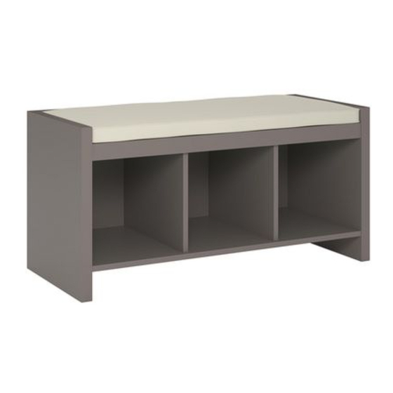
- Page 1 3-Cube Storage Bench Assembly Instructions Reference # Finish 211-4598 55365 White 211-4599 55363 Java 211-4600 55364 Cottage 211-4699 14601 Charcoal Tools Needed: hammer screwdriver 01-13968-00 11/20...
- Page 2 SAFETY PRECAUTIONS WARNING • This unit contains small parts which could be a choking hazard for small children. Children should be STOP under adult supervision at all times or serious injury could occur. • Always unload unit prior to moving the unit. The weight of personal belongings can cause the unit to become unstable and either tip or collapse.
-
Page 3: Table Of Contents
HARDWARE (H1) x 11 (H2) x 13 (H3) x 13 (H4) x 18 assembly screw cam post cam lock nail #5 mm x 38 mm (H5) x 20 (H6) x 4 (H7) x 6 wide dowel short dowel nail-on foot 8 mm x 30 mm 6 mm x 30 mm... - Page 4 DESCRIPTION QUANTITY left side panel right side panel top shelf back cleat front cleat middle dividers bottom shelf bottom cleat back panel cushion finished unfinished edge edge Unfinished edges are shaded in gray in the illustrations throughout this document. It is important to understand how finished edges go together.
-
Page 5: (H1) X
STEP 1 (H2) (H5) (H3) (H2) x 13 (H3) x 7 (H5) x 16 cam post cam lock wide dowel (H2) 8 mm x 30 mm (H5) 1. Secure cam posts (H2) into holes as shown. PLEASE NOTE: Cam post is secure when threads on screw are not showing. 2. - Page 6 STEP 2 (H1) (H1) x 3 (H5) x 2 assembly screw wide dowel #5 mm x 38 mm 8 mm x 30 mm (H5) 1. Insert WIDE dowels (H5) into holes in bottom of top cleat (D) as shown. 2. Align front cleat (E) with appropriate holes as shown and install. Tighten cam locks. 3.
-
Page 7: (H6) X 4
STEP 3 (H1) (H6) (H1) x 4 (H6) x 4 assembly screw short dowel #5 mm x 38 mm 6 mm x 30 mm 1. Insert SHORT dowels (H6) into holes in middle dividers (F) as shown. 2. Align middle dividers (F) with appropriate holes in top shelf (C) and use assembly screws (H1) to secure. -
Page 8: (H3) X 6
STEP 4 (H3) (H5) (H5) (H1) (H1) x 4 (H3) x 6 (H5) x 2 (H3) assembly screw cam lock wide dowel #5 mm x 38 mm 8 mm x 30 mm 1. Insert cam lock (H3) and press to bottom of holes in bottom shelf (G). Ensure arrow on cam locks are pointing towards outer edge as shown. 2. - Page 9 STEP 5 1. Align side panels (A & B) with appropriate holes as shown and install. 2. Tighten cam locks to secure side panels (A & B) to top shelf (C), bottom shelf (G), and bottom cleat (H).
- Page 10 STEP 6 (H4) x 18 (H7) x 6 nail nail-on foot 1. Flip the unit over so the unfinished edges are facing up. 2. Place back panel (I) onto unit (making sure the finished side of backer faces down) and center horizontally and vertically. 3.
- Page 11 STEP 7 1. Turn unit upright. 2. Peel backing from two strips of tape on underside of cushion (J). 3. Flip cushion (J) over so tape faces down, and position cushion on bench. Push down firmly for tape to adhere.
Need help?
Do you have a question about the 211-4598 and is the answer not in the manual?
Questions and answers